
PWM (Pulse Width Modulation) is a important feature of today’s every microcontroller due to its requirement for controlling many devices in every field of Electronics almost. PWM is widely used for motor controlling, lighting controlling etc. Sometime we do not use microcontroller in our applications and if we need to generate PWM without microcontroller then we prefer some general purpose ICs like op-amp, timers, pulse generators etc. Here we are using a 555 timer IC for generating PWM. 555 Timer IC is a very useful and general purpose IC which can be used in many applications.
Required Components:
- 555 timer IC -1
- 10K pot -1
- 100ohm resistor -1
- 0.1uF capacitor -1
- 1k resistor -1 (optional)
- Bread board -1
- 9v Battery -1
- LED -1
- multimeter or CRO -1
- Jumper wire -
- Battery connector -1
What is a PWM Signal?
Pulse Width Modulation (PWM) is a digital signal which is most commonly used in control circuitry. This signal is set high (5v) and low (0v) in a predefined time and speed. The time during which the signal stays high is called the “on time” and the time during which the signal stays low is called the “off time”. There are two important parameters for a PWM as discussed below:
Duty cycle of the PWM:
The percentage of time in which the PWM signal remains HIGH (on time) is called as duty cycle. If the signal is always ON it is in 100% duty cycle and if it is always off it is 0% duty cycle.
Duty Cycle =Turn ON time/ (Turn ON time + Turn OFF time)
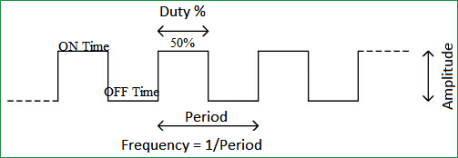
Frequency of a PWM:
The frequency of a PWM signal determines how fast a PWM completes one period. One Period is complete ON and OFF of a PWM signal as shown in the above figure. In our tutorial we will set a frequency of 5KHz.
We can notice if LED being OFF for half second and LED being ON for other half second. But if Frequency of ON and OFF times increased from ‘1 per second’ to ’50 per second’. The human eye cannot capture this frequency. For a normal eye the LED will be seen, as glowing with half of the brightness. So with further reduction of ON time the LED appears much lighter.
We have previously used PWM in many of our projects check them below:
- Pulse width Modulation with ATmega32
- PWM with Arduino Uno
- Generating PWM using PIC Microcontroller
- Raspberry Pi PWM Tutorial
- DC Motor Control with Raspberry Pi
- 1 watt LED Dimmer
- Arduino Based LED Dimmer using PWM
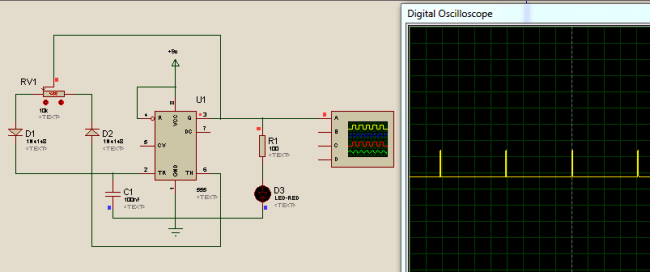
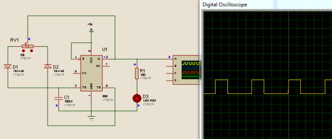
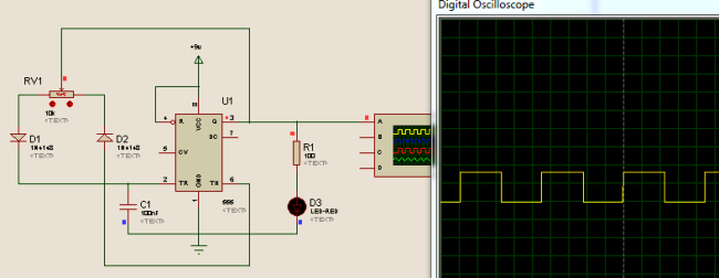
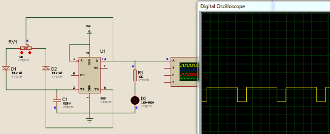
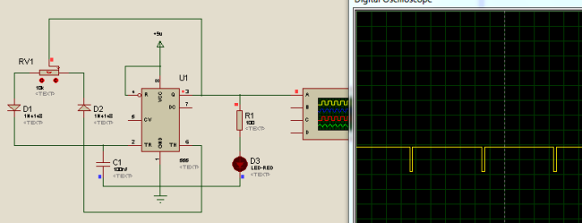
555 Timer PWM Generator Circuit Diagram and Explanation:

In this PWM generater circuit, as we mentioned above we have used 555 Timer IC for generating PWM signal. Here we have controlled the output frequency of the PWM signal by selecting resistor RV1 and capacitor C1. We have used a variable resistor in place of fixed resistor for changing duty cycle of the output signal. Capacitor Charging through D1 diode and Discharge through D2 diode will generates PWM signal at 555 timer's output pin.
Below formula is used for deriving the frequency of the PWM signal:
F = 0.693*RV1*C1
The whole working and demonstration of PWM generation is given in the Video at the end, where you can find the PWM effect on LED and can check it on Multimeter.
Simulating PWM generation using 555 Timer IC:
Below are some Snapshots:
Comments
It’s helpful thank you very much!
what is the input to pin 5
At LAST! I've been searching for an explanation of PWM and a circuit for it using a 555 timer. I've found lots of circuits!--but they all seemed to be based, at least in part, on the OPINION of the author. So you can imagine my elation to have run across your site, and the specific circuit I sought. Totally professional, totally clear, and totally TRUSTED!
You are what futurists 30 years ago predicted the Internet would do to improve civilization.
Thank you,
Bruce Ratcliffe, humble Electronics Teacher, Fresno, California
I don't see how F=.693 * RV1 * C1 works out to 5 kHz with the values shown for this article. RV1 is 10,000 and C1 is 100 nF (1E-7 farad).

Can i Generate 7mhz or 3.5mhz pwm signal on 50%duty cycle?
i am not able to generate this much pwm signal to the arduino .
and in your mind having some external ic is there to produced the 7mhz pwm signal then tell me.