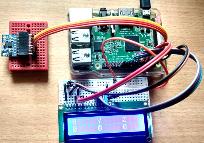
The MPU6050 sensor has many functions over the single chip. It consists a MEMS accelerometer, a MEMS gyro, and temperature sensor. This module is very accurate while converting analog values to digital because it has a 16bit analog to digital converter hardware for each channel. This module is capable to capture x, y and z channel at the same time. It has an I2C interface to communicate with the host controller. This MPU6050 module is a compact chip having both accelerometer and gyro. This is a very useful device for many applications like drones, robots, motion sensors. It is also called Gyroscope or Triple axis accelerometer.
Today in this article we are going to Interface this MPU6050 with Raspberry Pi and showing the values over 16x2 LCD.
Required Components:
- Raspberry Pi
- MPU-6050
- 10K POT
- Jumper wire
- Breadboard
- Power supply
MPU6050 Gyro Sensor:
MPU-6050 is an 8 pin 6 axis gyro and accelerometer in a single chip. This module works on I2C serial communication by default but it can be configured for SPI interface by configuring it register. For I2C this has SDA and SCL lines. Almost all the pins are multi-functioning but here we are proceeding only with I2C mode pins.
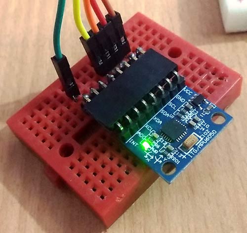
Pin Configuration:
Vcc:- this pin is used for powering the MPU6050 module with respect to ground
GND:- this is a ground pin
SDA:-SDA pin is used for data between controller and mpu6050 module
SCL:- SCL pin is used for clock input
XDA:- This is sensor I2C SDA Data line for configuring and reading from external sensors ((optional) not used in our case)
XCL:- This is sensor I2C SCL clock line for configuring and reading from external sensors ((optional) not used in our case)
ADO:- I2C Slave Address LSB (not applicable in our case)
INT:- Interrupt pin for indication of data ready.
We have previously interfaced MPU6050 with Arduino.
Description:
In this article, we are showing temperature, gyro and accelerometer readings over LCD using MPU6050 with Raspberry Pi. If you are new to Raspberry Pi then go through our Raspberry Pi tutorials section and learn getting started with Raspberry Pi.
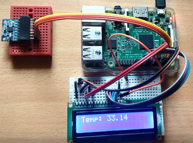
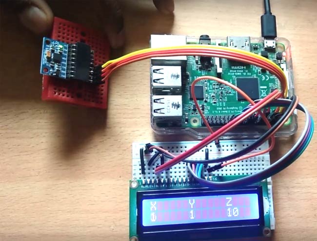
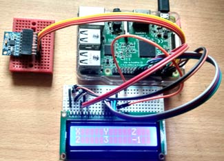
In this project, we have first shown temperature value over LCD and after some time we show gyro values and then after some time we have accelerometer readings as shown in the images below:
Circuit Diagram and Explanation:
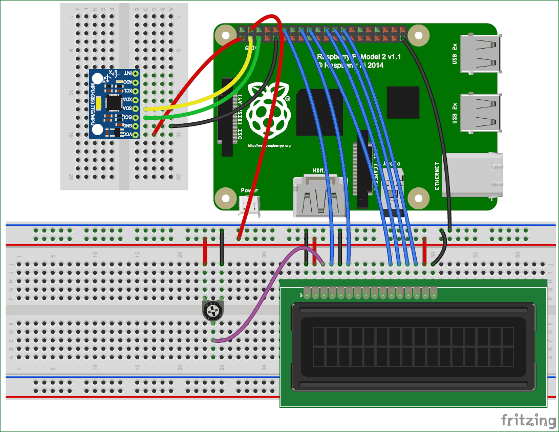
The circuit diagram, for interfacing MPU6050 with Raspberry Pi, is very simple here we have used an LCD and MPU6050. A 10k pot is used for controlling the brightness of the LCD. In connection with MPU6050, we have done 4 connections in which we have connected the 3.3v power supply and ground of MPU6050 to the 3.3v and ground of Raspberry Pi. SCL and SDA pins of MPU6050 is connected with Raspberry’s physical pin 3(GPIO2) and pin 5 (GPIO3). LCD’s RS, RW, and EN are directly connected to GPIO18, and 23 of raspberry pi. Data pin are directly connected to digital pin number GPIO24, GPIO25, GPIO8, and GPIO7. Learn more about interfacing LCD with Raspberry Pi here.
Configuring Raspberry Pi for MPU6050 Gyro sensor:
Before start programming, we need to enable i2c of Raspberry Pi by using given method:
Step 1: Enable I2C communication
Before installing Adafruit SSD1306 library we need to enable I2C communication in Raspberry Pi.
To do this type in Raspberry Pi console:
sudo raspi-config
And then a blue screen will appear. Now select interface option
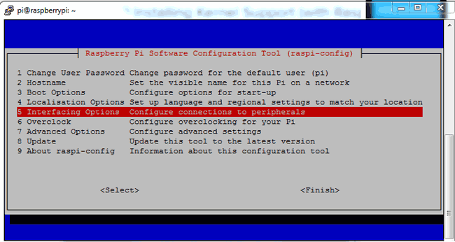
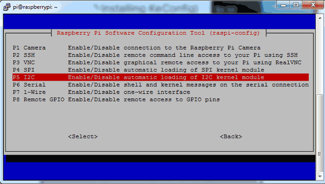
After this, we need to need to select I2C
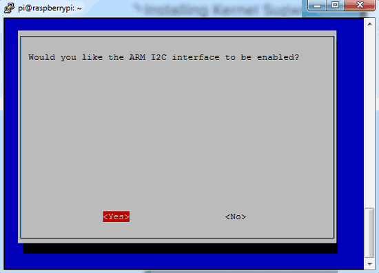
After this, we need to select yes and press enter and then ok
After this, we need to reboot raspberry pi by issuing below command:
sodo reboot
Step 2: Install python-pip and GPIO Library
sudo apt-get install build-essential python-dev python-pip
After this, we need to install raspberry pi GPIO library
sudo pip installs RPi.GPIO
Step 3: Install the smbus library
Finally, we need to install the smbus library in Raspberry Pi by using given command:
sudo apt-get install python-smbus

Step 4: Install the library MPU6050
After this we need to install MPU6050 library by using given command

sudo pip install mpu6050
Now we can find example codes in the examples. User can test that code by directly uploading to the Raspberry Pi or customize it according to requirement. Here we have displayed MPU6050’s X, Y and Z axis values on 16x2 LCD. You can find the full Python Code at the end of the Tutorial.
Programming Explanation:
Complete Python Code is given at the end here we are explaining few important part of the code.
In Python Program, we have imported some required library like time, smbus, and GPIO.
import smbus
import time

import RPi.GPIO as gpio
After this, we need to take some register address to configure MPU6050 and for getting values from the same. We have also taken some variables for calibrating and initializing bus for I2C.
PWR_M   = 0x6B
DIV   = 0x19
CONFIG       = 0x1A
GYRO_CONFIG  = 0x1B
INT_EN   = 0x38
ACCEL_X = 0x3B
ACCEL_Y = 0x3D
ACCEL_Z = 0x3F
GYRO_X  = 0x43
GYRO_Y  = 0x45
GYRO_Z  = 0x47
TEMP = 0x41
bus = smbus.SMBus(1)

Device_Address = 0x68   # device address
AxCal=0
AyCal=0
AzCal=0
GxCal=0
GyCal=0
GzCal=0
Then we have written some functions for Driving 16x2LCD like def begin(), def cmd(ch), def write(ch), def Print(str), def clear() etc. You can further check Interfacing of LCD with Raspberry Pi.
After this, we need to initialize the MPU6050 Module
def InitMPU():
     bus.write_byte_data(Device_Address, DIV, 7)
     bus.write_byte_data(Device_Address, PWR_M, 1)
     bus.write_byte_data(Device_Address, CONFIG, 0)
     bus.write_byte_data(Device_Address, GYRO_CONFIG, 24)
     bus.write_byte_data(Device_Address, INT_EN, 1)
     time.sleep(1)
After this, we need to write some functions to read values from MPU6050 and display them to LCD. Given function is used to read data from MPU6050
def readMPU(addr):
     high = bus.read_byte_data(Device_Address, addr)
     low = bus.read_byte_data(Device_Address, addr+1)
     value = ((high << 8) | low)
     if(value > 32768):
           value = value - 65536
     return value
Given function is used to read accelerometer and gyro meter data
def accel():
     x = readMPU(ACCEL_X)
     y = readMPU(ACCEL_Y)
     z = readMPU(ACCEL_Z)
     Ax = (x/16384.0-AxCal)
     Ay = (y/16384.0-AyCal)
     Az = (z/16384.0-AzCal)
     #print "X="+str(Ax)
     display(Ax,Ay,Az)
     time.sleep(.01)

def gyro():
      global GxCal
      global GyCal
      global GzCal
      x = readMPU(GYRO_X)
      y = readMPU(GYRO_Y)
      z = readMPU(GYRO_Z)
      Gx = x/131.0 - GxCal
      Gy = y/131.0 - GyCal
      Gz = z/131.0 - GzCal
      #print "X="+str(Gx)
      display(Gx,Gy,Gz)
      time.sleep(.01)
After this, we have written a temperature reading function
def temp():
  tempRow=readMPU(TEMP)
  tempC=(tempRow / 340.0) + 36.53
  tempC="%.2f" %tempC
  print tempC
  setCursor(0,0)
  Print("Temp: ")
  Print(str(tempC))
  time.sleep(.2)
def calibrate() function is used to calibrate the MPU6050 and def display() function is used to display the values on LCD. Check these functions in the full code given below.
After this, we have begun the LCD, initialize and calibrate the MPU6050 and then in while loop we have called all the all three set of values from MPU- temperature, accelerometer and gyro and showed them over LCD.
begin();
Print("MPU6050 Interface")
setCursor(0,1)
Print("Circuit Digest")
time.sleep(2)
InitMPU()
calibrate()

while 1:
  InitMPU()
  clear()

  for i in range(20):
    temp()
  clear()
  Print("Accel")
  time.sleep(1)
  for i in range(30):
    accel()
  clear()
  Print("Gyro")
  time.sleep(1)
  for i in range(30):
  gyro()
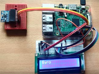
MPU6050 gyro and accelerometer both are used to detect the position and orientation of any device. Gyro uses earth gravity to determine the x,y and z-axis positions and accelerometer detects based on the rate of the change of movement. We already used the accelerometer with Arduino in many of our projects like:
Complete Project Code
import smbus
import time

import RPi.GPIO as gpio

PWR_M   = 0x6B
DIV   = 0x19
CONFIG       = 0x1A
GYRO_CONFIG  = 0x1B
INT_EN   = 0x38
ACCEL_X = 0x3B
ACCEL_Y = 0x3D
ACCEL_Z = 0x3F
GYRO_X  = 0x43
GYRO_Y  = 0x45
GYRO_Z  = 0x47
TEMP = 0x41
bus = smbus.SMBus(1)
Device_Address = 0x68   # device address

AxCal=0
AyCal=0
AzCal=0
GxCal=0
GyCal=0
GzCal=0


RS =18
EN =23
D4 =24
D5 =25
D6 =8
D7 =7

gpio.setwarnings(False)
gpio.setmode(gpio.BCM)
gpio.setup(RS, gpio.OUT)
gpio.setup(EN, gpio.OUT)
gpio.setup(D4, gpio.OUT)
gpio.setup(D5, gpio.OUT)
gpio.setup(D6, gpio.OUT)
gpio.setup(D7, gpio.OUT)


def begin():
  cmd(0x33)
  cmd(0x32)
  cmd(0x06)
  cmd(0x0C)
  cmd(0x28)
  cmd(0x01)
  time.sleep(0.0005)

def cmd(ch):
  gpio.output(RS, 0)
  gpio.output(D4, 0)
  gpio.output(D5, 0)
  gpio.output(D6, 0)
  gpio.output(D7, 0)
  if ch&0x10==0x10:
    gpio.output(D4, 1)
  if ch&0x20==0x20:
    gpio.output(D5, 1)
  if ch&0x40==0x40:
    gpio.output(D6, 1)
  if ch&0x80==0x80:
    gpio.output(D7, 1)
  gpio.output(EN, 1)
  time.sleep(0.005)
  gpio.output(EN, 0)
  # Low bits
  gpio.output(D4, 0)
  gpio.output(D5, 0)
  gpio.output(D6, 0)
  gpio.output(D7, 0)
  if ch&0x01==0x01:
    gpio.output(D4, 1)
  if ch&0x02==0x02:
    gpio.output(D5, 1)
  if ch&0x04==0x04:
    gpio.output(D6, 1)
  if ch&0x08==0x08:
    gpio.output(D7, 1)
  gpio.output(EN, 1)
  time.sleep(0.005)
  gpio.output(EN, 0)

def write(ch):
  gpio.output(RS, 1)
  gpio.output(D4, 0)
  gpio.output(D5, 0)
  gpio.output(D6, 0)
  gpio.output(D7, 0)
  if ch&0x10==0x10:
    gpio.output(D4, 1)
  if ch&0x20==0x20:
    gpio.output(D5, 1)
  if ch&0x40==0x40:
    gpio.output(D6, 1)
  if ch&0x80==0x80:
    gpio.output(D7, 1)
  gpio.output(EN, 1)
  time.sleep(0.005)
  gpio.output(EN, 0)
  # Low bits
  gpio.output(D4, 0)
  gpio.output(D5, 0)
  gpio.output(D6, 0)
  gpio.output(D7, 0)
  if ch&0x01==0x01:
    gpio.output(D4, 1)
  if ch&0x02==0x02:
    gpio.output(D5, 1)
  if ch&0x04==0x04:
    gpio.output(D6, 1)
  if ch&0x08==0x08:
    gpio.output(D7, 1)
  gpio.output(EN, 1)
  time.sleep(0.005)
  gpio.output(EN, 0)
def clear():
  cmd(0x01)

def Print(Str):
  l=0;
  l=len(Str)
  for i in range(l):
    write(ord(Str[i]))

def setCursor(x,y):
        if y == 0:
                n=128+x
        elif y == 1:
                n=192+x
        cmd(n)


def InitMPU():
bus.write_byte_data(Device_Address, DIV, 7)
bus.write_byte_data(Device_Address, PWR_M, 1)
bus.write_byte_data(Device_Address, CONFIG, 0)
bus.write_byte_data(Device_Address, GYRO_CONFIG, 24)
bus.write_byte_data(Device_Address, INT_EN, 1)
time.sleep(1)

def display(x,y,z):
      x=x*100
      y=y*100
      z=z*100
      x= "%d" %x
      y= "%d" %y
      z= "%d" %z
      setCursor(0,0)
      Print("X     Y     Z")
      setCursor(0,1)
      Print(str(x))
      Print("   ")
      setCursor(6,1)
      Print(str(y))
      Print("   ")
      setCursor(12,1)
      Print(str(z))
      Print("   ")

      print x
      print y
      print z


def readMPU(addr):
high = bus.read_byte_data(Device_Address, addr)
low = bus.read_byte_data(Device_Address, addr+1)
value = ((high << 8) | low)
if(value > 32768):
value = value - 65536
return value
def accel():
x = readMPU(ACCEL_X)
y = readMPU(ACCEL_Y)
z = readMPU(ACCEL_Z)

Ax = (x/16384.0-AxCal)
Ay = (y/16384.0-AyCal)
Az = (z/16384.0-AzCal)

#print "X="+str(Ax)
display(Ax,Ay,Az)
time.sleep(.01)

def gyro():
      global GxCal
      global GyCal
      global GzCal
      x = readMPU(GYRO_X)
      y = readMPU(GYRO_Y)
      z = readMPU(GYRO_Z)
      Gx = x/131.0 - GxCal
      Gy = y/131.0 - GyCal
      Gz = z/131.0 - GzCal
      #print "X="+str(Gx)
      display(Gx,Gy,Gz)
      time.sleep(.01)

def temp():
  tempRow=readMPU(TEMP)
  tempC=(tempRow / 340.0) + 36.53
  tempC="%.2f" %tempC
  print tempC
  setCursor(0,0)
  Print("Temp: ")
  Print(str(tempC))
  time.sleep(.2)

def calibrate():
  clear()
  Print("Calibrate....")
  global AxCal
  global AyCal
  global AzCal
  x=0
  y=0
  z=0
  for i in range(50):
      x = x + readMPU(ACCEL_X)
      y = y + readMPU(ACCEL_Y)
      z = z + readMPU(ACCEL_Z)
  x= x/50
  y= y/50
  z= z/50
  AxCal = x/16384.0
  AyCal = y/16384.0
  AzCal = z/16384.0

  print AxCal
  print AyCal
  print AzCal

  global GxCal
  global GyCal
  global GzCal
  x=0
  y=0
  z=0
  for i in range(50):
    x = x + readMPU(GYRO_X)
    y = y + readMPU(GYRO_Y)
    z = z + readMPU(GYRO_Z)
  x= x/50
  y= y/50
  z= z/50
  GxCal = x/131.0
  GyCal = y/131.0
  GzCal = z/131.0

  print GxCal
  print GyCal
  print GzCal


begin();
Print("MPU6050 Interface")
setCursor(0,1)
Print("Circuit Digest")
time.sleep(2)
InitMPU()
calibrate()
while 1:
  InitMPU()
  clear()
  for i in range(20):
    temp()
  clear()
  Print("Accel")
  time.sleep(1)
  for i in range(30):
    accel()
  clear()
  Print("Gyro")
  time.sleep(1)
  for i in range(30):
    gyro()
Comments
It worked for me, thank you!
It worked for me, thank you!
But do you have any advice on how to get it calibrated? My current temperature reading is 44 when I know my house is about 23. Also, while sitting at rest, total acceleration is at 2.173g



Thanks a lot!