
Making our projects Wireless always makes it to look cool and also extends the range in which it can be controlled. Starting from using a normal IR LED for short distance wireless control till an ESP8266 for worldwide HTTP control, there are lots of ways to control something wirelessly. In this project we learn how to build wireless projects using a 433 MHz RF module and AVR microcontroller.
In this project we do following things:-
- We use Atmega8 for the RF Transmitter and Atmega8 for the RF Receiver section.
- We interface an LED and a Pushbutton with Atmega8 microcontrollers.
- On the transmitter side, we Interface Pushbutton with Atmega and transmit the data. On the receiver side, we will receive the data wirelessly and show the output on LED.
- We use encoder and decoder IC to transmit 4 bit data.
- Reception Frequency is 433Mhz using cheap RF TX-RX module available in the market.
Components Required
- Atmega8 AVR Microcontroller (2)
- USBASP programmer
- 10-pin FRC cable
- Bread board (2)
- LEDs (2)
- Pushbutton (1)
- HT12D and HT12E pair
- RX-TX RF Module
- Resistors (10k,47k,1M)
- Jumper Wires
- 5V power supply
Software Used
We use CodeVisionAVR software for writing our code and SinaProg software for uploading our code to Atmega8 using USBASP programmer.
You can download these softwares from the given links:
CodeVisionAVR : http://www.hpinfotech.ro/cvavr_download.html
Before going into the schematics and codes, let’s understand the working of RF module with Encoder-Decoder ICs.
433MHz RF Transmitter and Receiver Module

Those are the transmitter and receiver modules we are using in the project. It is the cheapest module available for 433 MHz These modules accepts serial data in one channel.
If we see the specifications of the modules, the transmitter is rated for 3.5-12V operation as input voltage and the transmit distance is 20-200 meters. It does transmit in AM (Audio Modulation) protocol at 433 MHz frequency. We can transfer data at a speed of 4KB/S with 10mW power.
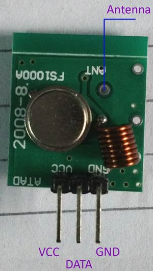
In the upper image we can see the pin-out of the Transmitter module. From the left to right the pins are VCC, DATA and GND. We can also add the antenna and solder it on the point denoted in the above image.
For the Receiver specification, the Receiver has a rating of 5V dc and 4MA Quiescent current as input. The receiving frequency is 433.92 MHz with a -105DB sensitivity.
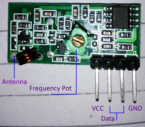
In the above image we can see the pin-out of the receiver module. The four pins are from Left to right, VCC, DATA, DATA and GND. Those middle two pins are internally connected. We can use any one or both. But it is a good practice to use both for lowering the noise coupling.
Also, one thing is not mentioned in the datasheet, the variable inductor or POT at the middle of the module is used for frequency calibration. If we couldn’t receive the transmitted data, there are possibilities that the transmitting and receiving frequencies are not matched. This is a RF circuit and we need to tune the transmitter at the perfect transmitted frequency point. Also, same as the transmitter, this module also has an Antenna port; we can solder wire in coiled form for longer reception.
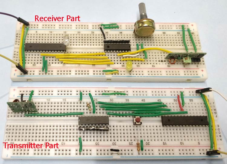
The transmission range is dependable on the voltage supplied to the Transmitter and the length of the antennas in both side. For this specific project we did not used external antenna and used 5V at the transmitter side. We checked with 5 meters distance and it worked perfectly.
Learn more about RF pair in the RF Transmitter and Receiver Circuit. You can understand more about the working of RF by checking following projects that uses RF pair:
- RF Controlled Robot
- IR to RF Converter Circuit
- RF Remote Controlled LEDs Using Raspberry Pi
- RF Controlled Home Appliances
Circuit Diagram
Circuit Diagram for RF Transmitter side

- Pin D7 of atmega8 -> Pin13 HT12E
- Pin D6 of atmega8 -> Pin12 HT12E
- Pin D5 of atmega8 -> Pin11 HT12E
- Pin D4 of atmega8 -> Pin10 HT12E
- Pushbutton to Pin B0 of Atmega.
- 1M-ohm resistor between pin15 and 16 of HT12E.
- Pin17 of HT12E to data pin of RF transmitter module.
- Pin 18 of HT12E to 5V.
- GND pin 1-9 and Pin 14 of HT12E and Pin 8 of Atmega.
Circuit Diagram for RF Receiver Side

- Pin D7 of atmega8 -> Pin13 HT12D
- Pin D6 of atmega8 -> Pin12 HT12D
- Pin D5 of atmega8 -> Pin11 HT12D
- Pin D4 of atmega8 -> Pin10 HT12d
- LED to Pin B0 of Atmega.
- Pin14 of HT12D to data pin of RF receiver module.
- 47Kohm resistor between pin15 and 16 of HT12D.
- GND pin 1-9 of HT12D and Pin 8 of Atmega.
- LED to pin 17 of HT12D.
- 5V to pin 7 of Atmega and pin 18 of HT12D.
Creating the Project for Atmega 8 using CodeVision
After installing these softwares follow the below steps to create project and writing code:
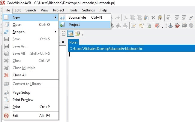
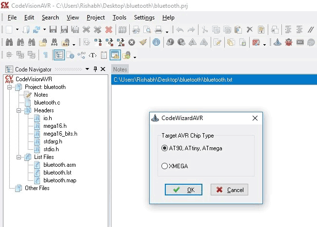
Step 1. Open CodeVision Click on File -> New -> Project. Confirmation Dialogue box will appear. Click On Yes
Step 2. CodeWizard will open. Click on first option i.e. AT90, and click OK.
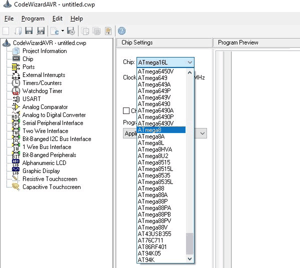
Step 3. Choose your microcontroller chip, here we will take Atmega8 as shown.
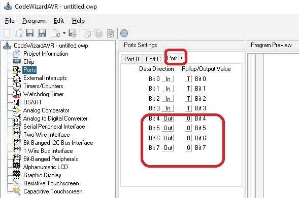
Step 4:- Click on Ports. In Transmitter part, Pushbutton is our input and 4 data lines are output. So, we have to initialize 4 pins of Atmega as output. Click on Port D. Make Bit 7, 6, 5 and 4 as out by clicking on it.
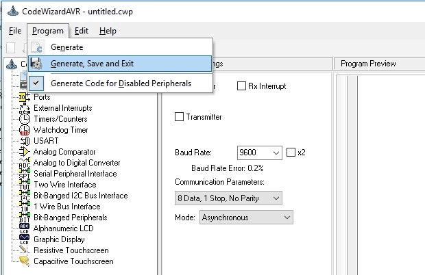
Step 5:- Click on Program -> Generate, Save and Exit. Now, more than half of our work is completed
Step 6:- Make a New folder on desktop so, that our files remains in folder otherwise it will be scattered on whole desktop window. Name your folder as you want and I suggest use the same name to save program files.
We will be having three dialogue boxes one after other to save files. Do the same with other two dialogue boxes which will appear after you save the first.
Now, your workspace looking like this.
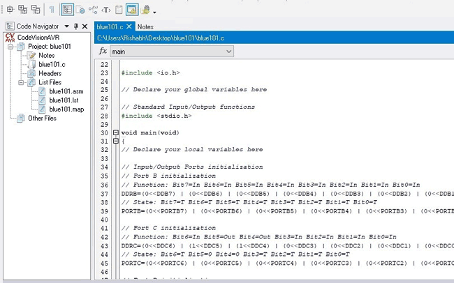
Our most of the work is completed with the help of the Wizard. Now, we have to write only few lines of code for transmitter and receiver part and That’s it…
Follow the same steps to create files for Receiver part. In receiver part, only Led is our output so make Port B0 bit to out.

CODE and Explanation
We will write code for toggling the LED wirelessly using RF. Complete code for both the Atmega at transmitter and Receiver sides are given at the end of this article.
Atmega8 code for RF Transmitter:
First Include delay.h header file to use delay in our code.
#include <io.h>
#include <delay.h>
void main(void)
{
Now, come to the last lines of code where you will find a while loop. Our main code will be in this loop.
In While loop, we will send 0x10 byte to PORTD when button is pressed and, will send 0x20 when button is not pressed. You can use any value to send.
while (1)
      {
  if(PINB.0 == 1)  {
        PORTD = 0x10;
          }
           if(PINB.0 == 0)  {
        PORTD = 0x20;
          }
      }
}
Atmega code for RF Receiver
First declare variables above void main function for storing incoming character from RF module.
#include <io.h>
#include <stdio.h>
#include <delay.h>
unsigned char byte = 0;
void main(void)
{
Now come to the while loop. In this loop, store incoming bytes to a char variable byte and check if the incoming byte is same as we write in our transmitter part. If bytes are same, make PortB.0 high and take NOT of PORTB.0 for toggling the LED.
while (1)
      {
   byte = PIND;
      if(PIND.7==0 && PIND.6==0 && PIND.5==0 && PIND.4==1)
      {
           PORTB.0 = ~PORTB.0;
            delay_ms(1000);
     }
   }
 }
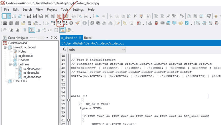
Build the Project
Our code is completed. Now, we have to Build our project. Click on Build the project icon as shown.
After building the project, a HEX file is generated in the Debug-> Exe folder which can be found in the folder which you have made previously to save your project. We will use this HEX file to upload in Atmega8 using Sinaprog software.
Upload the code to Atmega8
Connect your circuits according to given diagram to program Atmega8. Hookup the one side of FRC cable to USBASP programmer and other side will connect to SPI pins of microcontroller as described below:
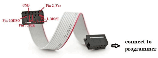
- Pin1 of FRC female connector -> Pin 17 ,MOSI of Atmega8
- Pin 2 connected to Vcc of atmega8 i.e. Pin 7
- Pin 5 connected to Reset of atmega8 i.e. Pin 1
- Pin 7 connected to SCK of atmega8 i.e. Pin 19
- Pin 9 connected to MISO of atmega8 i.e. Pin 18
- Pin 8 connected to GND of atmega8 i.e. Pin 8
Connect the remaining components on the breadboard as per circuit diagram and open the Sinaprog.
We will upload the above generated Hex file using the Sinaprog, so open it and Choose Atmega8 from Device drop down menu. Select the HEX file from the Debug-> Exe folder as shown.
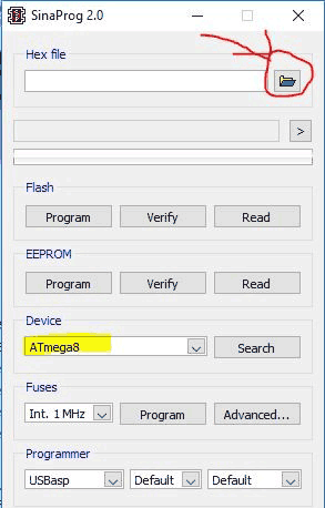
Now, Click on Program.
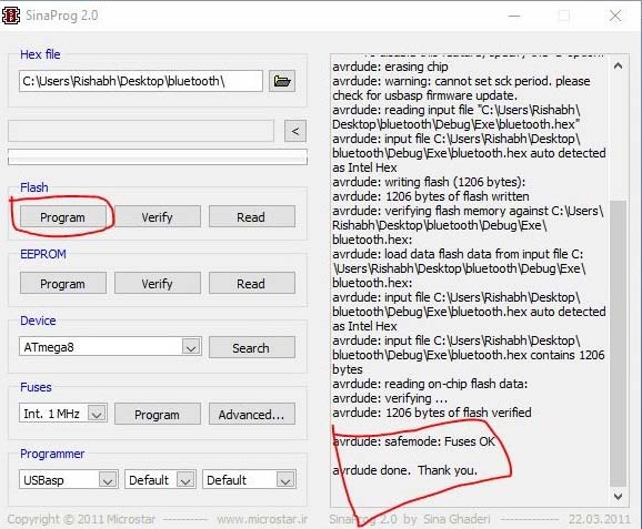
You are done and your Microcontroller is programmed. Use same steps to program another Atmega at receiver side.
Complete code and demonstration Video is given below.
Complete Project Code
Code for Transmitter Part:
#include <io.h>

#include <delay.h>

void main(void)

{

DDRB=(0<<DDB7) | (0<<DDB6) | (0<<DDB5) | (0<<DDB4) | (0<<DDB3) | (0<<DDB2) | (0<<DDB1) | (0<<DDB0);

// State: Bit7=T Bit6=T Bit5=T Bit4=T Bit3=T Bit2=T Bit1=T Bit0=0

PORTB=(0<<PORTB7) | (0<<PORTB6) | (0<<PORTB5) | (0<<PORTB4) | (0<<PORTB3) | (0<<PORTB2) | (0<<PORTB1) | (0<<PORTB0);
// Port C initialization

// Function: Bit6=In Bit5=In Bit4=In Bit3=In Bit2=In Bit1=In Bit0=In

DDRC=(1<<DDC6) | (1<<DDC5) | (1<<DDC4) | (1<<DDC3) | (1<<DDC2) | (1<<DDC1) | (1<<DDC0);

// State: Bit6=T Bit5=T Bit4=T Bit3=T Bit2=T Bit1=T Bit0=T

PORTC=(0<<PORTC6) | (0<<PORTC5) | (0<<PORTC4) | (0<<PORTC3) | (0<<PORTC2) | (0<<PORTC1) | (0<<PORTC0);
// Port D initialization

// Function: Bit7=In Bit6=In Bit5=In Bit4=In Bit3=In Bit2=In Bit1=In Bit0=In

DDRD=(1<<DDD7) | (1<<DDD6) | (1<<DDD5) | (1<<DDD4) | (1<<DDD3) | (1<<DDD2) | (1<<DDD1) | (1<<DDD0);

// State: Bit7=T Bit6=T Bit5=T Bit4=T Bit3=T Bit2=T Bit1=T Bit0=T

PORTD=(0<<PORTD7) | (0<<PORTD6) | (0<<PORTD5) | (0<<PORTD4) | (0<<PORTD3) | (0<<PORTD2) | (0<<PORTD1) | (0<<PORTD0);

while (1)

      {

  if(PINB.0 == 1)  {

        PORTD = 0x10;

          }

           if(PINB.0 == 0)  {

        PORTD = 0x20;

          }

      }

}
Code for Receiver Part:
#include <io.h>

#include <delay.h>

// Declare your global variables here

unsigned char byte = 0;

unsigned char lightON = 0;//light status

int LED_status = 0;

void main(void)

{

// Input/Output Ports initialization

// Port B initialization

// Function: Bit7=In Bit6=In Bit5=In Bit4=In Bit3=In Bit2=In Bit1=Out Bit0=Out

DDRB=(0<<DDB7) | (0<<DDB6) | (0<<DDB5) | (0<<DDB4) | (0<<DDB3) | (0<<DDB2) | (0<<DDB1) | (1<<DDB0);

// State: Bit7=T Bit6=T Bit5=T Bit4=T Bit3=T Bit2=T Bit1=0 Bit0=0

PORTB=(0<<PORTB7) | (0<<PORTB6) | (0<<PORTB5) | (0<<PORTB4) | (0<<PORTB3) | (0<<PORTB2) | (0<<PORTB1) | (0<<PORTB0);

// Port D initialization

// Function: Bit7=In Bit6=In Bit5=In Bit4=In Bit3=In Bit2=In Bit1=In Bit0=In

DDRD=(0<<DDD7) | (0<<DDD6) | (0<<DDD5) | (0<<DDD4) | (0<<DDD3) | (0<<DDD2) | (0<<DDD1) | (0<<DDD0);

// State: Bit7=T Bit6=T Bit5=T Bit4=T Bit3=T Bit2=T Bit1=T Bit0=T

PORTD=(0<<PORTD7) | (0<<PORTD6) | (0<<PORTD5) | (0<<PORTD4) | (0<<PORTD3) | (0<<PORTD2) | (0<<PORTD1) | (0<<PORTD0);

while (1)

      {

     byte = PIND;

      if(PIND.7==0 && PIND.6==0 && PIND.5==0 && PIND.4==1 && LED_status==0)

      {

           PORTB.0 = ~PORTB.0;

            delay_ms(1000);

      }

      }

}

Thank You Very Much. I loved all the tutorials.