

Almost every electronic hobbyist must have faced a scenario where he or she must measure the frequency of signal generated by a clock or a counter or a timer. We can use oscilloscope to do the job, but not all of us can afford an oscilloscope. We can buy equipment for measuring the frequency but all these devices are costly and are not for everyone. With that in mind we are going to design a simple yet efficient Frequency Counter using Arduino Uno and Schmitt trigger gate.
This Arduino Frequency Counter is cost effective and can be easily made, we are going to use ARDUINO UNO for the measuring the frequency of signal, UNO is the heart of project here.
To test the Frequency Meter, we are going to make a dummy signal generator. This dummy signal generator will be made by using a 555 timer chip. The timer circuit generates a square wave which will be provided to UNO for testing.
With everything in place we will have a Arduino Frequency meter and a square wave generator. Arduino can also be used to generate other kind of waveforms like sine wave, saw tooth wave etc.
Required Components:
- 555 timer IC and 74LS14 Schmitt trigger gate or NOT gate.
- 1K Ω resistor(2 pieces), 100Ω resistor
- 100nF capacitor (2 pieces), 1000µF capacitor
- 16*2 LCD,
- 47KΩ pot,
- Breadboard and some connectors.
Circuit Explanation:
The circuit diagram of the Frequency Measurement using Arduino is shown in below figure. Circuit is simple, a LCD is interfaced with Arduino to display the measured frequency of signal. ‘Wave Input’ is going to Signal Generator Circuit, from which we are feeding signal to Arduino. A Schmitt trigger gate (IC 74LS14) is used to ensure that only rectangular wave is fed to Arduino. For filtering the noise we have added couple of capacitors across power. This Frequency Meter can measure frequencies up to 1 MHz.

Signal generator circuit and Schmitt trigger have been explained below.
Signal Generator using 555 Timer IC:
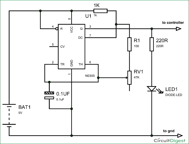
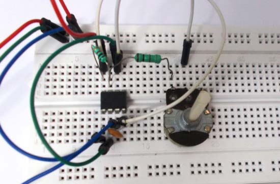
First of all we will talk about 555 IC based square wave generator, or should I say 555 Astable Multivibrator. This circuit is necessary because, with the Frequency Meter in place we must have a signal whose frequency is known to us. Without that signal we will never be able to tell the working of Frequency Meter. If we have a square have of known frequency we can use that signal to test the Arduino Uno Frequency Meter and we can tweak it for adjustments for accuracy, in case of any deviations. The picture of Signal Generator using 555 Timer IC is given below:
Typical circuit of 555 in Astable mode is given below, from which we have derived the above given Signal Generator Circuit.
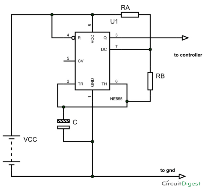
The output signal frequency depends on RA, RB resistors and capacitor C. The equation is given as,
Frequency (F) = 1/ (Time period) = 1.44/ ((RA+RB*2)*C).
Here RA and RB are resistance values and C is capacitance value. By putting the resistance and capacitance values in above equation we get the frequency of output square wave.
One can see that RB of above diagram is replaced by a pot in the Signal Generator Circuit; this is done so that we can get variable frequency square wave at the output for better testing. For simplicity, one can replace the pot with a simple resistor.
Schmitt Trigger Gate:
We know that all the testing signals are not square or rectangular waves. We have triangular waves, tooth waves, sine waves and so on. With the UNO being able to detect only the square or rectangular waves, we need a device which could alter any signals to rectangular waves, thus we use Schmitt Trigger Gate. Schmitt trigger gate is a digital logic gate, designed for arithmetic and logical operations.
This gate provides OUTPUT based on INPUT voltage level. A Schmitt Trigger has a THERSHOLD voltage level, when the INPUT signal applied to the gate has a voltage level higher than the THRESHOLD of the logic gate, OUTPUT goes HIGH. If the INPUT voltage signal level is lower than THRESHOLD, the OUTPUT of gate will be LOW. We don’t usually get Schmitt trigger separately, we always have a NOT gate following the Schmitt trigger. Schmitt Trigger working is explained here: Schmitt Trigger Gate
We are going to use 74LS14 chip, this chip has 6 Schmitt Trigger gates in it. These SIX gates are connected internally as shown in below figure.
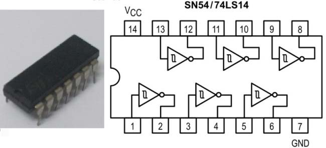
The Truth Table of Inverted Schmitt Trigger gate is show in below figure, with this we have to program the UNO for inverting the positive and negative time periods at its terminals.
Now we will feed any type of signal to ST gate, we will have rectangular wave of inverted time periods at the output, we will feed this signal to UNO.
Arduino Frequency Counter Code Explanation:
Code for this frequency measurement using arduino is quite simple and easily understandable. Here we are explaining the pulseIn function which is mainly responsible measuring the frequency. The Uno has a special function pulseIn, which enables us to determine the positive state duration or negative state duration of a particular rectangular wave:
Htime = pulseIn(8,HIGH);
Ltime = pulseIn(8, LOW);
The given function measures the time for which High or Low level is present at PIN8 of Uno. So in a single cycle of wave, we will have the duration for the positive and negative levels in Micro seconds. The pulseIn function measures the time in micro seconds. In a given signal, we have high time = 10mS and low time = 30ms (with frequency 25 HZ). So 30000 will be stored in Ltime integer and 10000 in Htime. When we add them together we will have the Cycle Duration, and by inverting it we will have the Frequency.
Complete code and video for this Frequency Meter using Arduino are given below.
Complete Project Code
#include <LiquidCrystal.h>
LiquidCrystal lcd(2, 3, 4, 5, 6, 7);
int Htime;              //integer for storing high time

int Ltime;                //integer for storing low time

float Ttime;            // integer for storing total time of a cycle

float frequency;        //storing frequency
void setup()

{

    pinMode(8,INPUT);

    lcd.begin(16, 2);

}

void loop()

{

    lcd.clear();

    lcd.setCursor(0,0);

    lcd.print("Frequency of signal");
    Htime=pulseIn(8,HIGH);      //read high time

    Ltime=pulseIn(8,LOW);        //read low time


    Ttime = Htime+Ltime;
    frequency=1000000/Ttime;    //getting frequency with Ttime is in Micro seconds

    lcd.setCursor(0,1);

    lcd.print(frequency);

    lcd.print(" Hz");

    delay(500);

}
Comments
this project is simple to
this project is simple to make and vry interesting.
oscilloscope
can i use this circuit as an oscilloscope?and where to modify??
Interestin
Hi, going to make this when the parts come in. I know I have some 555s around here some place, but I can't for the life of me find them, probably have a couple Schmid triggers as well but you can never have too many parts, and for the cost of them now days, ordering a lot of 10 for 3 bucks doesn't seem to much to invest in a good signal generator. Now to decide which display I want to use, and which project box will house it. Details, details, always details...>>>>
No you cannot, The frequency
No you cannot, The frequency counter cannot measure frequencies higher than 6Mhz. So it cannot detect radio signals.
Measuring radio frequencies
Yes. You can measure radio frequencies of up to about 6 MHz. If you add a pre-scaler (divide by N) you can then change the code to multiply the displayed frequency by the pre-scale division and see the actual input frequency. To improve accuracy you can add or subtract a few microseconds in the code to
compensate if your Arduino crystal is off frequency by a small amount.
Arduino Based Frequency Meter
Yes you can use this idea to make an Arduino based frequency meter but for the higher frequencies encountered on HF bands you will need to add a pre-scaler. That will bring the HF signals down to where they can be measured by the pulse-width functions in Arduino libraries.
A better way might be to use something like a 74HC4060 as a pre-scaler and make your Arduino software interrupt-driven so it toggles at LOW-->HIGH transitions of the pre-scaled signal. Then use the micro-seconds() counter to determine time between subsequent LOW-->HIGH transitions and calculate the frequency. Since some Arduino boards use a ceramic resonator for the 16 MHz oscillator you may see some temperature induced drift. Frequency correction can be done in software but this does not stop the drift. There are some Arduinio Pro-mini boards available from Ebay vendors that use a real crystal for the 16 MHz oscillator. These are much better for Arduino-based frequency counters.
[ K7HKL ]
Accuracy issue
I built this circuit as per your instructions & tested it against my O-scope. I get a non-lin addative drift of about 15hz per 100 ie.: 100hz= 114.7 to 15ish (arduino output floats) , 200hz= 230ish etc from my frequecy generator. My O-scope verifies that the generator is right on the money. Is this an inherant accuracy expectancy or could something else be at play here? How accurate where your readings? Any ideas or input greatly appreciated.
Improving the code
/* fcounter.ino
This code is based on a simpler version that has become standard
among Arduino users. Some problems with the original code have
been fixed and operation speed has been improved (slightly).
Arv K7HKL 2016
STRATEGY:
This code is actually a period counter with conversion of period to
frequency in software. Refresh time is less for higher frequency
inputs, which provides a pseudo auto-ranging operation.
A prescaler is needed for frequencies higher than one third CPU
Clock. If a prescaler is used, its division factor should be set in the
"int prescale = N;" code line. This will cause frequency to be multiplied
by the pre-scal factor before it is written to the LCD. Higher prescale
factors may noticeably slow counting of VLF and audio signals.
*/
#include <LiquidCrystal.h>
LiquidCrystal lcd(2, 3, 4, 5, 6, 7); // LCD pin connections
int Htime; // integer for storing high time
int Ltime; // integer for storing low time
float Ttime; // integer for storing total time of a cycle
float frequency; // for storing frequency
int prescale = 1; // change this if a pre-scaler is added
void setup()
{
pinMode(8,INPUT); // pin D8 is frequency input
lcd.begin(16, 2); // set LCD = 16 char by 2 lines
lcd.clear(); // clear the whole LCD
lcd.setCursor(0,0); // set cursor to the first character, top line
lcd.print(" Frequency"); // label the LCD top line
}
void loop()
{
Htime=pulseIn(8,HIGH); //read high time
Ltime=pulseIn(8,LOW); //read low time
Ttime = Htime+Ltime; // total time = high time + low time
frequency=1000000/Ttime; //calculate frequency from Ttime in Micro seconds
frequency = frequency * prescale; // handle any pre-scaler division factor
lcd.setCursor(0,1); // set cursor to first character of LCD second line
lcd.print(" "); // clear the second line
lcd.setCursor(0,1); // set cursor to first character of LCD second line
lcd.print(frequency); // print frequency on LCD second line
lcd.print(" Hz"); // add suffix to show measurement is in Hz.
}
Airband Receiver
Would this work with a frequency range of 108-136 MhZ? I would like to add this to a Airband Receiver project. What would I have to change in order to get these frequencies displayed? "int prescale = 1; // change this if a pre-scaler is added"
Would you still recommend the 74HC4060 chip substitution?
Freq Counter Project: LCD Sourcing and LiquidCrystal.h
Great project ! I'm just starting with the Arduino and would like to put this project together. I'm in the USA and I can't find the LCD JHD_162ALCD referred to in the companion article (LCD is interfaced with Arduino ). Can anyone provide a source for the LCD or is there an alternative (please provide part nbr) ? Also, the sketch refers to the LiquidCrystal.h library: Being new to the Arduino is this part of the Arduino code base or do I need to dowload the library from some where? Any help is appreciated ! Thanks.
You can use any 16x2 LCD, no
You can use any 16x2 LCD, no need to get exact one. And LiquidCrystal.h is the part of Arduino code base, you just need to use latest Arduino IDE to burn the code: https://www.arduino.cc/en/Main/Software
You can buy any 16*2
You can buy any 16*2 Alphanumeric LCD module that is available in your local market. It should be easy for you to find one in you local hardware store. The LCD library for Arduino will be loaded by default in your Arduino IDE so you dont have to worry about it.
All the best.
Frecuency counter
Hi, I want to measure a phonic wheel sensor which submit between 0 hz to 1300 hz, I wonder if this method could shows accurate results for this range?
Lee
This circuit can measure upto
This circuit can measure upto 1MHz of frequency but it is most suitable for measuring frequency of digitally generated Square wave.
Thank you for sharing
this simple code has helped me to simplify my ground capacitive moisture meter .
I had all the pins in Arduino One engaged and I could not use the Frequencycounter library that requires the pin D5 free.
thank you !!
Best regards friend
after programming whether the
after programming whether the led name (L) will blink or not blink or stand steadily
Can i use 20*4 lcd display ?
Can i use 20*4 lcd display ??If possible ,how?
why the hell the frequency is
why the hell the frequency is changing when we are changing 47k pot for same signal. For a particular signal it should show some frequency,for different signals it should show different frequency . Frequency counter means it should count the frequency of the given signal ,for example if we give our household power signal it should show approx 50 Hz. I am not able to understand the main idea behind signal generator(using 555 timer), when the input signal is fed to the arduino through schmitt trigger gate arduino will count number of pulses passing per second from which we get frequency then what is the use of dummy signal generator there ???
house hold AC can damage the
house hold AC can damage the circuit, and if you have square wave of known frequency you can provide input from that too. Here 555 is just to give demonstration of the protect.
The IC 7414
Can we use a simple NOT gate instead of your Schmidt Trigger NOT gate???
If not plz tell in short why. What's special with this 7414 gate?
Frequency counter some proposel
1.
You must find the correct libraries for the LCD you have.For me I use
#include <LCD.h>
#include <LiquidCrystal_I2C.h>
2.
You made one measuring of time and then display the floating number of frequency. You will get a more correct measuring as an average of several measuring's. I have placed a for .. until loop with counter to 1000 and add up Ttime in variabel Tsum and then calculate frequency from Tsum/1000. You can also convert this frequency to an integer if you like
frekvens=long(frequency+0.5);
3.
I have a better way don't use pulseIn() function because this is an indirect way and have many complicated process's , but count the number of transitions from HIGH to LOW (or LOW to HIGH) in a second that is frequency.
/*
**Frequency counter - count the number of trasitions from HIGH to LOW in a second
**The use of LCD is taken from other programs
*/
#include <Wire.h>
#include <LCD.h>
#include <LiquidCrystal_I2C.h>
#define I2C_ADDR 0x27 // <<----- Add your address here. Find it from I2C Scanner
#define BACKLIGHT_PIN 3
#define En_pin 2
#define Rw_pin 1
#define Rs_pin 0
#define D4_pin 4
#define D5_pin 5
#define D6_pin 6
#define D7_pin 7
long frekvens;//storing frequency - danish for frequency
long number; // counter for transitions
long time1; // starttime for 1 second in micros()
long time; // measering time in micros()
LiquidCrystal_I2C lcd(I2C_ADDR,En_pin,Rw_pin,Rs_pin,D4_pin,D5_pin,D6_pin,D7_pin);
void setup()
{
lcd.begin (16,2); // <<----- My LCD was 16x2
pinMode(8,INPUT); //impuls ind på digital ben nr 8
Serial.begin(9600);//initialize the serial
// Switch on the backlight
lcd.setBacklightPin(BACKLIGHT_PIN,POSITIVE);
lcd.setBacklight(HIGH);
lcd.home (); // go home
}
void loop()
{
number=0;
time1=micros();
do
/* loop for one second*/
{
if (digitalRead(8)==HIGH)
{
do
{
/* empty loop waiting for transition*/
}
while (digitalRead(8)==HIGH);
/* now from HIGH to LOW */
number++;
}
time=micros();
}
while (time<(time1+1000000));
lcd.clear();
lcd.setCursor(0,0);
lcd.print("Frequency :");
lcd.setCursor(0,1);
lcd.print(number);
lcd.print(" Hz");
delay(1000);
}
PulseIn is not working
Hello community,
I have a problem regarding to the pulseIn() function. I am using an Arduino Micro for my work.
The problem is that I get false results in PWM measurement. I used the Code shown on this page. My PWM Signal is simulated by the Arduino and has 2Hz.
My Serial Monitor just Shows for HIGH and LOW both 0 and for the frequency it shows inf (Infinite?? Dont know what that is). I already tried to change pins, the timeout length and even used external HIGH or LOW to measure a pulse which still gave me a 0 as time in Serial Monitor....
here is my Code:
int PWM = 8; // Input for the frequency
int READYLED = 10; // PWM generator
float T = 0;
int L;
int H;
float frequency;
void setup() {
Serial.begin(9600);
pinMode(PWM, INPUT);
pinMode(READYLED, OUTPUT);
}
void loop(){
digitalRead(PWM);
H = pulseIn(PWM, HIGH, 300);
L = pulseIn(PWM, LOW, 300);
T = H+L;
frequency=1000000/T;
Serial.println(frequency);
digitalWrite(READYLED, HIGH);
delay(250);
digitalWrite(READYLED; LOW);
delay(250);
}
it would be nice if you guys could help me with that problem.
best regards,
Marcel
I doubt problem is more with
I doubt problem is more with your hardware. Are you sure you are getting nice PWM at the input? Also what is the use of "digitalRead(PWM);"
You can try using the forum for this question
I may be wrong, but aren't
I may be wrong, but aren't you trying to read pwm with the same arduino that generates it? When you want to detect a pulse it is not there because at the end of the loop you turned the signal low. H and L are 0, so dividing 1000000 by 0 gives you an error.
Need better diagram
Can you PLEASE post a diagram of how the 555 and SN54 are connected? I had it working last week and for the life of me I cannot get it working again! Better yet, post a diagram of the entire circuit. Whenever I run the sketch I only get ~60Hz, which is the powerline frequency. I had it working perfectly and then when I went to implement it into my lighted electric drum project it no longer worked.
Schmitt trigger IC substitute
Very nice and well explained project. My questions are:
No1: may I use HEF40106BP (CMOS HEX SCHMITT TRIGGER) as a substitute of 74LS14?
No2: Quote:"For filtering the noise we have added couple of capacitors across power." (End of quote.)
Do you mean the +5V DC power pin and Gnd pin of the Adruino board, or the Vcc pin of the Schmitt trigger IC?
Best regards
Frequency Range for this arduino Frequency Counter
I am certainly not a expert about this stuff, or about anything, for that matter, so, if you see something wrong with my conclusions, please let me know.
-------------------------------------------------------------------------------
My conclusions:
Below 707 Hz, it is able to resolve on one Hz difference.
At ten kiloHertz, resolution is down to about 100 Hertz.
Audio range: Even if you consider the top of the range to be 15 kHz, you can't come any closer than about 300 Hz to the actual frequency at that point.
At one hundred Kilohertz, the minimum difference it can resolve is 11.1 kilohertz. For instance, if you wanted to know whether the actual signal was 100 kHz or 108 kHz, you'd never know. All you would see is some number in that range, and, possibly that number jumping up or down by 11.1 kiloHertz from one sample to the next.
At one megaHertz, there would be a one megaHertz minimum resolution! No, it really won't be useful anywhere near to one megahertz and certainly not beyond.
If you can live with this lack of precision, or whatever you call it , then this circuit is for you.
Nice post
I've hooked up my Mega 2560 to an 1Mhz oscillator can coing through a SN74HC14N.
I've changed the program shightly so I output to the serial console and the output fields are as follows
Frequency, Ttime, Htime, Ltime
Below is a sample of the output:
   1312 -32768 17470 762
   1838 0 17416 544
   2024 0 17399 494
   2410 -32768 17359 415
   3802 -32768 17283 263
   2639 -32768 17341 379
   1433 -32768 17454 698
   2028 -32768 17398 493
   1946 -32768 17408 514
   2646 0 17341 378
   1869 -16384 17413 535
   6757 0 17172 148
   1284 -16384 17474 0
   2597 -32768 17344 385
   2028 -32768 17398 493
   2639 -32768 17341 379
   2639 -32768 17341 379
   3003 -32768 17318 333
   2000 0 17402 500
   2000 0 17402 500
   2028 -32768 17398 493
   3049 0 17316 328
   2024 0 17399 494
   2597 -32768 17344 385
   1949 16384 17408 513
   2469 -32768 17354 405
   1988 -32768 17403 503
For the frequency, shouldn't I see 1000's ? Instead I'm seeing mostly 2000's
Is this output wrong?
Manyt thanks for any help with this
UPDATE: It seems the the
UPDATE: It seems the the delay(500) has a impact on the frequency. The figures above were taken with no delay.
When I used the delay (500) in the program I got:
    913 -8192 17544 1095
    706 0 17585 1416
    919 0 17544 1088
    912 8192 17545 1097
    944 24576 17540 1059
    756 16384 17573 1322
    874 0 17551 1144
   1026 -16384 17523 975
    806 0 17563 1240
    977 0 17536 1024
    913 -8192 17544 1095
    841 -24576 17556 1189
    876 -16384 17550 1142
    710 8192 17584 1409
    934 -8192 17541 1071
    806 8192 17563 1241
    937 24576 17541 1067
   1003 16384 17529 997
    782 -16384 17567 1278
Not too sure what the delay is doing.
How accurate is this for
How accurate is this for frequencies between 0.5hz and 4hz?

I like only Audio amplifier. so maked to Aurduino measurement. Hz, Amp, Mili Amp, Wattes, Etc.