

Schmitt Trigger gate is a digital logic gate, designed for arithmetic and logical operations. It provides OUTPUT based on INPUT voltage level. A Schmitt Trigger has a THERSHOLD voltage level, when the INPUT signal applied to the gate has a voltage level higher than the THRESHOLD of the logic gate, OUTPUT goes HIGH. If the INPUT signal level is lower than THRESHOLD, the OUTPUT of gate will be LOW. You can also check our article on Introduction to Schmitt Trigger if you wish to learn more about the basics of Schmitt Triggers.
In the chosen chip the Schmitt Trigger gate is followed by a NOT gate, So we get logic OUTPUT opposite to Schmitt Trigger OUTPUT. So the OUTPUT of INVERTED Schmitt Trigger will be LOW when the INPUT signal voltage level crosses THRESHOLD level of gate, in all other cases the OUTPUT will be HIGH.
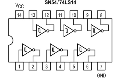
Here we are going to use 74LS14 IC for demonstration, this chip has 6 Schmitt Trigger gates in it. These SIX gate are connected internally as shown in the below figure.
These gates have limitations for working voltage and input logic frequency. When these limitations are not considered the chip may damage permanently, so one should pay attention while selecting the logic gates.
Components
Power supply (5v)
1K, 220Ω resistors
74LS14 HEX SCHMITT TRIGGER GATE IC
1 LED, button
100nF capacitor
Connecting wires and breadboard
Circuit Diagram & Explanation
The truth table of Inverted Schmitt Trigger gate is shown in below figure.
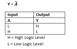
As of circuit diagram an Inverted Schmitt Trigger gate has one output for one input. As by the truth table, the output of NOT gate will be high when the input is low. The output of NOT gate should be low when the input is high.
So the NOT gate provides output which is inverted logic of input, except the INPUT signal voltage level must cross THREHOLD voltage of Schmitt Trigger gate. If not the NOT gate followed by Schmitt Trigger will not see any INPUT and so the OUTPUT will be HIGH all the time.
In this circuit we are going to pull down both input of a gate to ground through a 1KΩ resistor. And then the input is connected to power through a button.
So when the button is pressed the corresponding pin of gate goes high. So with this button we can realize the truth table of Inverted Schmitt Trigger gate. When the button is pressed the input will go high, with this the output will go low and so the LED should be off. When the button is released the input will go LOW, with this the OUTPUT will go HIGH and so the LED should be ON.

These pull down resistor are necessary as the chosen CHIP is a positive edge triggering one. If the resistor is ignored the circuit might generate unpredictable results.
The capacitor here is for neutralizing the bouncing effect of button. Although the capacitor here is not compulsory, putting them might smooth the working of gate. The main purposes of Schmitt Trigger gate is for nullifying the bouncing effect of the buttons.
