

Programming is always fun and Arduino is a wonderful platform if you are just getting started with Embedded programming. In this tutorial we will build our own calculator with Arduino. The values can be sent in through a keypad (4×4 keypad) and result can be viewed on a LCD screen (16×2 Dot-matrix). This calculator could perform simple operations like Addition, Subtraction, Multiplication and Division with whole numbers. But once you understand the concept you can implement even scientific functions with Arduino’s built in functions.
At the end of this project you will know how to use a 16x2 LCD and Keypad with Arduino and also how easy it is to program for them using the readily available libraries. You will also understand how to program your Arduino for accomplishing a particular task.
Materials Required:
- Arduino Uno (Any version will work)
- 16×2 LCD Display
- 4×4 Keypad
- 9V Battery
- Breadboard and Connecting wires
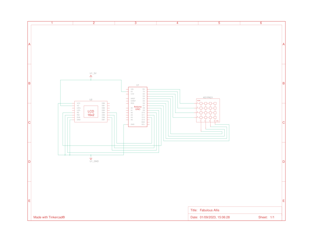
Circuit Diagram:

The complete circuit diagram of this Arduino Calculator Project is given above. The +5V and ground connection shown in the circuit diagram can be obtained from the 5V and ground pin of the Arduino. The Arduino itself can be powered from your laptop or through the DC jack using a 12V adapter or 9V battery.
We are operating the LCD in 4-bit mode with Arduino so only the last four data bits of the LCD is connected to Arduino. The Keyboard will have 8 output pins which have to be connected from pin 0 to pin 7 as shown above. You can use the following connection table to verify your connection with Arduino, you can also check 4x4 Keypad interfacing with Arduino.
|
Arduino Pin Name: |
Connected to: |
|
D0 |
1st pin of the keyboard |
|
D1 |
2nd pin of the keyboard |
|
D2 |
3rd pin of the keyboard |
|
D3 |
4th pin of the keyboard |
|
D4 |
5th pin of the keyboard |
|
D5 |
6th pin of the keyboard |
|
D6 |
7th pin of the keyboard |
|
D7 |
8th pin of the keyboard |
|
D8 |
Register select pin of LCD (pin 4) |
|
D9 |
Enable pin of LCD (pin 6) |
|
D10 |
Data pin 4 (pin 11) |
|
D11 |
Data pin 4 (pin 11) |
|
D12 |
Data pin 4 (pin 11) |
|
D13 |
Data pin 4 (pin 11) |
|
+5V |
Connected to Vdd pin of LCD (pin 2) |
|
Ground |
Connected to Vss,Vee and RW pin of LCD (pin 1,3 and 5) |
Some Arduino boards might show an error while uploading program if there are anything connected to pin 0 and pin1, so if you experience any just remove the keypad while uploading the program.
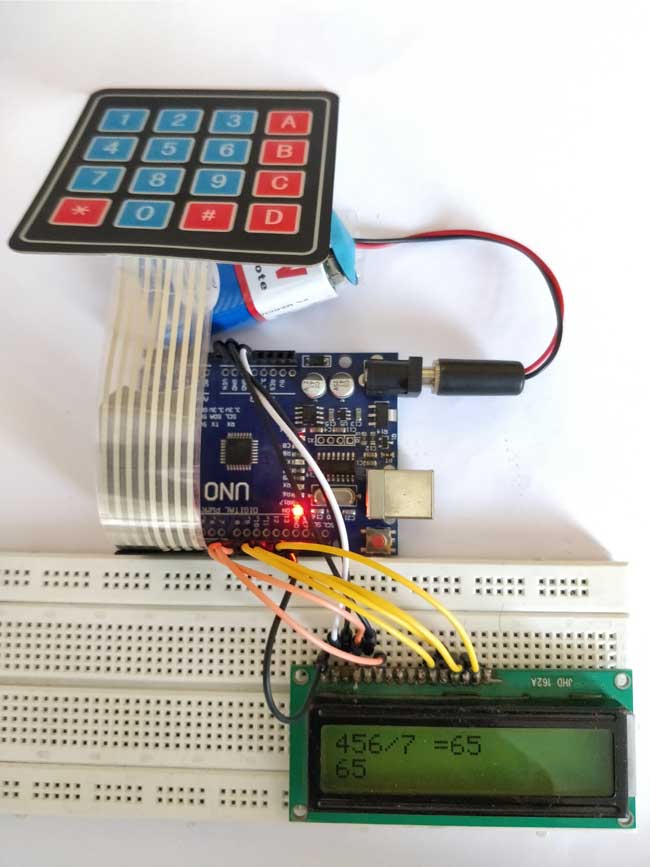
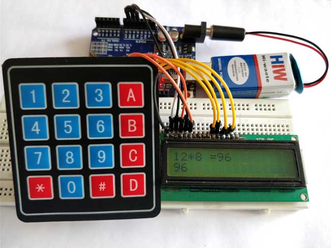
Once your connections are done your hardware will look something like this below
Arduino Calculator Program:
The complete Arduino program for this project is given at the end of this project. The code is split into small meaningful chunks and explained below.
As told earlier we are going to interface a LCD and keypad with Arduino using libraries. So let’s add them to our Arduino IDE first. The library for LCD is already included in your Arduino by default so we need not worry about it. For Keypad library click on the link to download it from Github. You will get a ZIP file, then add this lib to Arduino by Sketch -> Include Library -> Add .ZIP file and point the location to this downloaded file. Once done we are all set for programming.
Even though we have used a library for using a keypad we have to mention few details (shown below) about the keypad to the Arduino. The variable ROWS and COLS will tell how many rows and columns our keypad has and the keymap shows the order in which the keys are present on the keyboard. The keypad that i am using in this project looks like this below to the key map also represents the same.
Further below we have mentioned to which pins the Keypad is connected using the variable array rowPins and colPins.
const byte ROWS = 4; // Four rows
const byte COLS = 4; // Three columns

// Define the Keymap
char keys[ROWS][COLS] = {
  {'1','2','3','A'},
  {'4','5','6','B'},
  {'7','8','9','C'},
  {'*','0','#','D'}
};
byte rowPins[ROWS] = { 0, 1, 2, 3 };// Connect keypad ROW0, ROW1, ROW2 and ROW3 to these Arduino pins.
byte colPins[COLS] = { 4, 5, 6, 7 }; // Connect keypad COL0, COL1 and COL2 to these Arduino pins.
Once we have mentioned what type of keypad we are using and how it is connected, we can create the keypad using those details using the line below
Keypad kpd = Keypad( makeKeymap(keys), rowPins, colPins, ROWS, COLS ); // Create the Keypad
Similarly we also have to tell to which pins of the Arduino the LCD is connected to. According to our circuit diagram the definitions would be like below
const int rs = 8, en = 9, d4 = 10, d5 = 11, d6 = 12, d7 = 13; //Pins to which LCD is connected
LiquidCrystal lcd(rs, en, d4, d5, d6, d7); //create the LCD
Inside the setup function, we just display the name of the project and then proceed to while loop where the main project lies.
Basically, we have to check if anything is being typed on the keypad, if typed we have to recognize what is being typed and then convert it to a variable when the “=” is pressed we have to calculate the result and then finally display it on the LCD. This is exactly what is done inside the loop function as shown below
key = kpd.getKey(); //storing pressed key value in a char

if (key!=NO_KEY)
DetectButtons();

if (result==true)
CalculateResult();

DisplayResult();
What happens inside each function is explained using the comment lines, go through the complete code below, fiddle around with it to understand how it actually works. If you have any doubt on a specific line, feel free to use the comment section or the forums.
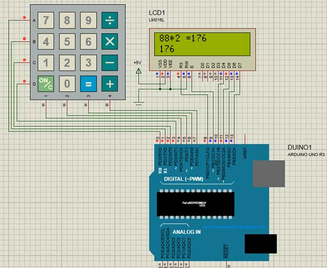
Simulation of Arduino Calculator:
We can also try simulating the project using Proteus software. Proteus does not have an Arduino component on it’s own, but can be easily downloaded and added to its library. Once you have the Arduino component on Proteus, just add Alphanumeric LCD and Keypad to make the connection as shown in the circuit diagram.
Then download the hex file from here and add it to the Arduino by double clicking on board in Proteus and point the “program file” to this downloaded hex file. A snap shot of the simulation is shown below, the complete working is shown in the video below.
Note: The hex file given is not as same as the original of the program given below. It has been modified to since the keymap of the simulation keypad and the actual hardware keypad is different.
Working of Arduino Calculator:
Make the connections as per circuit diagram and upload the code below. If it shows error make sure you have added the library as per the instruction given above. You can also try the simulation to check if the problem is with your hardware. If everything is done as it’s supposed to be, then your hardware will look something like this below with the LCD displaying this
Since the keypad used here does not have proper markings on it I have assumed the Alphabets to be operators as listed below
|
Character on Keypad |
Assumed to be |
|
“A” |
Addition (+) |
|
“B” |
Subtraction (-) |
|
“C” |
Multiplication (*) |
|
“D” |
Division (/) |
|
“*” |
Clear (C) |
|
“#” |
Equals (=) |
You can use a marker to write over what each button actually represents.
With that done, you can directly start using the calculator. Types the number and will appear on the second line press the operand and type your second number finally press the “#” key to get your result. You can also try building this Touchscreen based Arduino calculator.
Complete Project Code
/*

 * Arduino Keypad calculator Program

 */

#include <LiquidCrystal.h> //Header file for LCD from https://www.arduino.cc/en/Reference/LiquidCrystal

#include <Keypad.h> //Header file for Keypad from https://github.com/Chris--A/Keypad
const byte ROWS = 4; // Four rows

const byte COLS = 4; // Three columns
// Define the Keymap

char keys[ROWS][COLS] = {
  {'7','8','9','D'},
  {'4','5','6','C'},
  {'1','2','3','B'},
  {'*','0','#','A'}
};
byte rowPins[ROWS] = { 0, 1, 2, 3 };// Connect keypad ROW0, ROW1, ROW2 and ROW3 to these Arduino pins.

byte colPins[COLS] = { 4, 5, 6, 7 }; // Connect keypad COL0, COL1 and COL2 to these Arduino pins.
Keypad kpd = Keypad( makeKeymap(keys), rowPins, colPins, ROWS, COLS ); //  Create the Keypad
const int rs = 8, en = 9, d4 = 10, d5 = 11, d6 = 12, d7 = 13; //Pins to which LCD is connected

LiquidCrystal lcd(rs, en, d4, d5, d6, d7);

 long Num1,Num2,Number;

 char key,action;

 boolean result = false;


void setup() {

  lcd.begin(16, 2); //We are using a 16*2 LCD display

  lcd.print("DIY Calculator"); //Display a intro message

  lcd.setCursor(0, 1);   // set the cursor to column 0, line 1

  lcd.print("-CircuitDigest"); //Display a intro message
   delay(2000); //Wait for display to show info

    lcd.clear(); //Then clean it

}
void loop() {


key = kpd.getKey(); //storing pressed key value in a char
if (key!=NO_KEY)

DetectButtons();
if (result==true)

CalculateResult();
DisplayResult();

}
void DetectButtons()

{

     lcd.clear(); //Then clean it

    if (key=='*') //If cancel Button is pressed

    {Serial.println ("Button Cancel"); Number=Num1=Num2=0; result=false;}


     if (key == '1') //If Button 1 is pressed

    {Serial.println ("Button 1");

    if (Number==0)

    Number=1;

    else

    Number = (Number*10) + 1; //Pressed twice

    }


     if (key == '4') //If Button 4 is pressed

    {Serial.println ("Button 4");

    if (Number==0)

    Number=4;

    else

    Number = (Number*10) + 4; //Pressed twice

    }


     if (key == '7') //If Button 7 is pressed

    {Serial.println ("Button 7");

    if (Number==0)

    Number=7;

    else

    Number = (Number*10) + 7; //Pressed twice

    }


    if (key == '0')

    {Serial.println ("Button 0"); //Button 0 is Pressed

    if (Number==0)

    Number=0;

    else

    Number = (Number*10) + 0; //Pressed twice

    }


     if (key == '2') //Button 2 is Pressed

    {Serial.println ("Button 2");

     if (Number==0)

    Number=2;

    else

    Number = (Number*10) + 2; //Pressed twice

    }


     if (key == '5')

    {Serial.println ("Button 5");

     if (Number==0)

    Number=5;

    else

    Number = (Number*10) + 5; //Pressed twice

    }


     if (key == '8')

    {Serial.println ("Button 8");

     if (Number==0)

    Number=8;

    else

    Number = (Number*10) + 8; //Pressed twice

    }


    if (key == '#')

    {Serial.println ("Button Equal");

    Num2=Number;

    result = true;

    }


     if (key == '3')

    {Serial.println ("Button 3");

     if (Number==0)

    Number=3;

    else

    Number = (Number*10) + 3; //Pressed twice

    }


     if (key == '6')

    {Serial.println ("Button 6");

    if (Number==0)

    Number=6;

    else

    Number = (Number*10) + 6; //Pressed twice

    }


     if (key == '9')

    {Serial.println ("Button 9");

    if (Number==0)

    Number=9;

    else

    Number = (Number*10) + 9; //Pressed twice

    }
      if (key == 'A' || key == 'B' || key == 'C' || key == 'D') //Detecting Buttons on Column 4

  {

    Num1 = Number;

    Number =0;

    if (key == 'A')

    {Serial.println ("Addition"); action = '+';}

     if (key == 'B')

    {Serial.println ("Subtraction"); action = '-'; }

     if (key == 'C')

    {Serial.println ("Multiplication"); action = '*';}

     if (key == 'D')

    {Serial.println ("Devesion"); action = '/';}
    delay(100);

  }


}
void CalculateResult()

{

  if (action=='+')

    Number = Num1+Num2;
  if (action=='-')

    Number = Num1-Num2;
  if (action=='*')

    Number = Num1*Num2;
  if (action=='/')

    Number = Num1/Num2;

}
void DisplayResult()

{

  lcd.setCursor(0, 0);   // set the cursor to column 0, line 1

  lcd.print(Num1); lcd.print(action); lcd.print(Num2);


  if (result==true)

  {lcd.print(" ="); lcd.print(Number);} //Display the result


  lcd.setCursor(0, 1);   // set the cursor to column 0, line 1

  lcd.print(Number); //Display the result

}
Comments
Download the keypad library from github. the link is in code.
Then copy the keypad folder in you arduino libraries folder at the install location.
the error will go away.
what's the use of this calculator
plz help to solve this error
C:\Users\Hp\Documents\Arduino\sketch_apr19a\sketch_apr19a.ino: In function 'void setup()':
sketch_apr19a:49: error: redefinition of 'void setup()'
void setup() {
^
C:\Users\Hp\Documents\Arduino\sketch_apr19a\sketch_apr19a.ino:6:6: note: 'void setup()' previously defined here
void setup() {
^
C:\Users\Hp\Documents\Arduino\sketch_apr19a\sketch_apr19a.ino: In function 'void loop()':
sketch_apr19a:59: error: redefinition of 'void loop()'
void loop() {
^
C:\Users\Hp\Documents\Arduino\sketch_apr19a\sketch_apr19a.ino:11:6: note: 'void loop()' previously defined here
void loop() {
^
exit status 1
redefinition of 'void setup()'
As the console states the error is error: redefinition of 'void setup()'
Meaning you have used setup() twice in your program.
Where is the link to the hex file ?
my lcd is turning on but it doesnt show the commands
pls tell how to send this code to arduino app on my laptop
Could you readjust this code for the Arduino Nano Every, please.
On the arduino nano every there is an error common to all nano every.
where can i copy this project?
idk what's the problem but mine isn't working I am trying to make a digital version of it here a pic

when your code compile in ARDUINO, here I found some error .. how can I solve this.. the error message given below >>>
Arduino: 1.8.5 (Windows 7), Board: "Arduino/Genuino Uno"
C:\Users\atik\Documents\Arduino\sketch_apr15a\sketch_apr15a.ino:2:20: fatal error: Keypad.h: No such file or directory
#include <Keypad.h>
^
compilation terminated.
exit status 1
Error compiling for board Arduino/Genuino Uno.
This report would have more information with
"Show verbose output during compilation"
option enabled in File -> Preferences.