

In this tutorial we will learn How to make out PIC projects wireless by interfacing a Bluetooth Module (HC-06). In our previous tutorial we have already learnt How to use USART module in our PIC Microcontroller and established communication between PIC and Computer. If you are an absolute beginner then check here for our all the PIC Tutorials, where we have started from the scratch, like learning MPLAB and XC8, interfacing LED, LCD, using Timers, ADC, PWM etc.
Here, we have used the popular Bluetooth module HC-06. Using this module we can receive and send information wirelessly from our PIC MCU to a mobile application or a computer. Communication between PIC and HC-06 is established using the USART module present in the PIC Microcontroller. You can also use the HC-05. We again operate on the same Asynchronous 8-bit mode, but this time we will modify our code a bit so that it works with the Bluetooth module. Hence learning UART tutorial beforehand is an added advantage for this project.
In this tutorial, we will toggle a LED by sending on or off command from our Smart phone. We will use an Android application called Bluetooth Terminal which can send and receive data over Bluetooth. If we send a char ‘1’ from the app the light will be turned ON in the PIC board and we will get an acknowledgment back to the phone that the light has been turned on. Similarly we can send ‘0’ from phone to turn it off. This way we can control the LED light on our PIC board, similar to the UART tutorial but now wirelessly. Complete Program and the Detailed Video is given at the end of this tutorial.
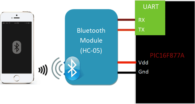
The basic block diagram for the setup is shown below.
Requirements:
Hardware:
- PIC16F877A Perf Board
- HC-05 or HC-06 Bluetooth Module
- Computer (for programming )
- Mobile Phone
- PICkit 3 Programmer
Software:
Bluetooth Module HC-06:
Bluetooth can operate in the following two modes:
- Command Mode
- Operating Mode
In Command Mode we will be able to configure the Bluetooth properties like the name of the Bluetooth signal, its password, the operating baud rate etc. The Operating Mode is the one in which we will be able to send and receive data between the PIC Microcontroller and the Bluetooth module. Hence in this tutorial we will be toying only with the Operating Mode. The Command mode will be left to the default settings. The Device name will be HC-05 (I am using HC-06) and the password will be 0000 or 1234 and most importantly the default baud rate for all Bluetooth modules will be 9600.
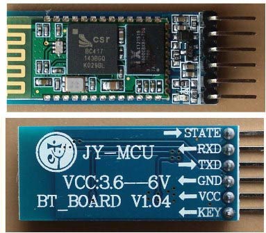
The module works on 5V supply and the signal pins operate on 3.3V, hence a 3.3V regulator is present in the module itself. Hence we need not worry about it. Out of the six pins only four will be used in the Operating mode. The pin connection table is shown below
|
S.No |
Pin on HC-05/HC-06 |
Pin name on MCU |
Pin number in PIC |
|
1 |
Vcc |
Vdd |
31st pin |
|
2 |
Vcc |
Gnd |
32nd pin |
|
3 |
Tx |
RC6/Tx/CK |
25th pin |
|
4 |
Rx |
RC7/Rx/DT |
26th pin |
|
5 |
State |
NC |
NC |
|
6 |
EN (Enable) |
NC |
NC |
Check our other projects to learn more about Bluetooth module HC-05 with other microcontrollers:
- Bluetooth Controlled Toy Car using Arduino
- Bluetooth Controlled Home Automation System using 8051
- Voice Controlled Lights using Raspberry Pi
- Smart Phone Controlled FM Radio using Arduino and Processing
- Mobile Phone Controlled Robot Car using G-Sensor and Arduino
Programming PIC Microcontroller for Bluetooth Communication:
Like all modules (ADC, Timer, PWM) we should also initialize our Bluetooth module. The initialization will be similar to UART initialization but we need to make some changes for the Bluetooth to work flawlessly with our PIC16F877A MCU. Let’s define the configuration bits and start with the Bluetooth initialization function.
Initializing Bluetooth:
Almost all the Bluetooth modules in the market work at a baud rate of 9600, it is very important to set your baud rate same as that of Bluetooth modules operating baud rate, here we set SPBRG=129 since we are operating at 20Mhz clock frequency with 9600 as baud rate. Hence the above initialization will work only for Bluetooth modules operating at 9600 baud rate. It is also mandatory to have the high speed baud rate bit BRGH enabled. This will help in setting an accurate baud rate.
//******Initialize Bluetooth using USART********//
void Initialize_Bluetooth()
{
   //Set the pins of RX and TX//
    TRISC6=1;
    TRISC7=1;

  //Set the baud rate using the look up table in datasheet(pg114)//
    BRGH=1;      //Always use high speed baud rate with Bluetooth else it wont work
    SPBRG  =129;

    //Turn on Asyc. Serial Port//
    SYNC=0;
    SPEN=1;

    //Set 8-bit reception and transmission
    RX9=0;
    TX9=0;

   //Enable transmission and reception//
    TXEN=1;
    CREN=1;

    //Enable global and ph. interrupts//
    GIE = 1;
    PEIE= 1;

    //Enable interrupts for Tx. and Rx.//
    RCIE=1;
    TXIE=1;
}
//___________BT initialized_____________//
If you have a BT module which operates at a different baud rate, then you can refer the look up table below to find out your value for the SPBRG.
Loading data into Bluetooth:
Once the function is initialized we have three functions in our program to send and receive data from Bluetooth. Unlike UART we have few things to consider here before we can transmit or receive data. The Bluetooth module has a Transmit and Receive buffer inside it, the data sent to it will be stored in the Tx buffer. This data will not be broadcasted (sent on air) unless a carriage return is sent to the module. Hence in order to transmit data we have to load the Rx buffer of BT and then broadcast it using carriage return.
The above working can be easily achieved by using the following functions. The below function can be used when we have to load only one character into the Rx buffer. We load the data into the TXREG register and wait till it is processed by check on the flag TXIF and TRMT by using while loops.
//Function to load the Bluetooth Rx. buffer with one char.//
void BT_load_char(char byte)
{
    TXREG = byte;
    while(!TXIF);
    while(!TRMT);
}
//End of function//
Below function is used to load a string into the Rx buffer of the Bluetooth module. The string is split into characters and each character is sent to the BT_load_char() function.
//Function to Load Bluetooth Rx. buffer with string//
void BT_load_string(char* string)
{
    while(*string)
    BT_load_char(*string++);
}
//End of function/
Broadcasting data over Bluetooth:
Till now we have just transmitted information into the Rx buffer of the HC-05 module. Now we must instruct it to broadcast the data over air by using this function.
//Function to broadcast data from RX. buffer//
void broadcast_BT()
{
  TXREG = 13;
  __delay_ms(500);
}
//End of function//
In this function we send a value 13 into the TXREG register. This value 13 is nothing but the decimal equivalent for carriage (refer ASCII chart). Then a small delay is created for the broadcaster to start.
Reading data from Bluetooth:
Similar to UART, the below function is used to read data from the Bluetooth
//Function to get a char from Rx.buffer of BT//
char BT_get_char(void)
{
    if(OERR) // check for over run error
    {
        CREN = 0;
        CREN = 1; //Reset CREN
    }

    if(RCIF==1) //if the user has sent a char return the char (ASCII value)
    {
    while(!RCIF);
    return RCREG;
    }
    else //if user has sent no message return 0
        return 0;
}
//End of function/
If the user has sent a data, this function will return that particular data which can be saved in a variable and processed. If the user has not sent anything the function will return zero.
Main function:
We have used all the above explained functions inside or main function. We send some introductory message and then wait for the user to send some values based on which we toggle the RED led light connected to the RB3 pin on our Perf board.
void main(void)
{
    //Scope variable declarations//
    int get_value;
    //End of variable declaration//

    //I/O Declarations//
    TRISB3=0;
    //End of I/O declaration//

   Initialize_Bluetooth(); //lets get our bluetooth ready for action

   //Show some introductory message once on power up//
   BT_load_string("Bluetooth Initialized and Ready");
   broadcast_BT();
   BT_load_string("Press 1 to turn ON LED");
   broadcast_BT();
   BT_load_string("Press 0 to turn OFF LED");
   broadcast_BT();
   //End of message//

    while(1) //The infinite lop
    {

    get_value = BT_get_char(); //Read the char. received via BT

    //If we receive a '0'//
        if (get_value=='0')
          {
             RB3=0;
             BT_load_string("LED turned OFF");
             broadcast_BT();
          }

    //If we receive a '1'//
        if (get_value=='1')
          {
             RB3=1;
             BT_load_string("LED turned ON");
             broadcast_BT();
          }
    }
}
Check the Full Program in the Code Section Below.
Circuit Diagram and Hardware Setup:
Circuit connections for this project is very simple, we simply have to power up the Bluetooth module and connect the Tx to the 26th pin of PIC and Rx to the 25th pin of PIC as shown in the circuit diagram below:

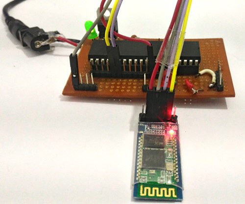
Now let us proceed to the hardware. Once the connection is done it should look something like this.
Controlling LED using Bluetooth Mobile Application:
Now let us get our Android application ready. Download the application called Bluetooth Terminal from the App store or use this link. Once the application is downloaded and installed, turn on your PIC perf board which we are using since beginning. The small LED light on your Bluetooth Module should be flashing to indicate that it is powered on and is actively looking for a phone to establish a connection.
Now get into the Bluetooth Settings of your phone and search for new Bluetooth device you should be able to see the name HC-05 or HC-06 based on your module. I am using HC-06 hence my phone shows the following display. Then try paring with it and it will ask for a password. Enter the password as 1234 (for some it might be 0000) and click OK as shown below.
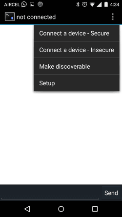
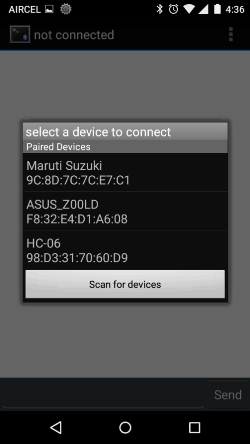
After the paring is successful, open the Bluetooth Terminal application that we just installed. Get into the settings option and select “Connect a device – Secure” as shown below. This will open a pop box where all our paired devices will be listed as shown below. Select the HC-05 or HC-06 module.
Once the connection is established, the light on the Bluetooth module which was flashing so far must have become constant to indicate that it has successfully connected to your mobile. And we should get the introductory message from our Program like shown below.
Now press ‘1’ to turn on the LED light and press ‘0’ to turn off the light. The complete working will be shown in the Video. Your mobile screen will look something like this shown below.
So that is it guys, we have learnt How to Interface Bluetooth module to our PIC microcontroller, now with the aid of this we can try wireless projects. There are lots of projects which uses Bluetooth, you can try them or come up with your own Idea and do share them in the comment section. Also check our previous project with Bluetooth terminal app and HC-05 like Smart Phone Controlled Home Automation Using Arduino and Smart Phone Controlled Digital Code Lock using Arduino.
Hope, this tutorial helped you! If you got stuck somewhere, kindly use the comment section.
Complete Project Code
// CONFIG

#pragma config FOSC = HS       // Oscillator Selection bits (HS oscillator)

#pragma config WDTE = OFF       // Watchdog Timer Enable bit (WDT disabled)

#pragma config PWRTE = OFF       // Power-up Timer Enable bit (PWRT enabled)

#pragma config BOREN = OFF        // Brown-out Reset Enable bit (BOR enabled)

#pragma config LVP = OFF        // Low-Voltage (Single-Supply) In-Circuit Serial Programming Enable bit (RB3 is digital I/O, HV on MCLR must be used for programming)

#pragma config CPD = OFF        // Data EEPROM Memory Code Protection bit (Data EEPROM code protection off)

#pragma config WRT = OFF        // Flash Program Memory Write Enable bits (Write protection off; all program memory may be written to by EECON control)

#pragma config CP = OFF         // Flash Program Memory Code Protection bit (Code protection off)

//End of CONFIG registers
#define _XTAL_FREQ 20000000

#include<xc.h>
//******Initialize Bluetooth using USART********//

void Initialize_Bluetooth()

{

   //Set the pins of RX and TX//

    TRISC6=1;

    TRISC7=1;


  //Set the baud rate using the look up table in datasheet(pg114)//

    BRGH=1;      //Always use high speed baud rate with Bluetooth else it wont work

    SPBRG  =129;


    //Turn on Asyc. Serial Port//

    SYNC=0;

    SPEN=1;


    //Set 8-bit reception and transmission

    RX9=0;

    TX9=0;
   //Enable transmission and reception//

    TXEN=1;

    CREN=1;


    //Enable global and ph. interrupts//

    GIE = 1;

    PEIE= 1;


    //Enable interrupts for Tx. and Rx.//

    RCIE=1;

    TXIE=1;

}

//___________BT initialized_____________//
//Function to load the Bluetooth Rx. buffer with one char.//

void BT_load_char(char byte)

{

    TXREG = byte;

    while(!TXIF);

    while(!TRMT);

}

//End of function//
//Function to Load Bluetooth Rx. buffer with string//

void BT_load_string(char* string)

{

    while(*string)

    BT_load_char(*string++);

}

//End of function//
//Function to broadcast data from RX. buffer//

void broadcast_BT()

{

  TXREG = 13;

  __delay_ms(500);

}

//End of function//
//Function to get a char from Rx.buffer of BT//

char BT_get_char(void)

{

    if(OERR) // check for over run error

    {

        CREN = 0;

        CREN = 1; //Reset CREN

    }


    if(RCIF==1) //if the user has sent a char return the char (ASCII value)

    {

    while(!RCIF);

    return RCREG;

    }

    else //if user has sent no message return 0

        return 0;

}

//End of function/
void main(void)

{

    //Scope variable declarations//

    int get_value;

    //End of variable declaration//


    //I/O Declarations//

    TRISB3=0;

    //End of I/O declaration//


   Initialize_Bluetooth(); //lets get our bluetooth ready for action


   //Show some introductory message once on power up//

   BT_load_string("Bluetooth Initialized and Ready");

   broadcast_BT();

   BT_load_string("Press 1 to turn ON LED");

   broadcast_BT();

   BT_load_string("Press 0 to turn OFF LED");

   broadcast_BT();

   //End of message//


    while(1) //The infinite lop

    {


    get_value = BT_get_char(); //Read the char. received via BT


    //If we receive a '0'//

        if (get_value=='0')

          {

             RB3=0;

             BT_load_string("LED turned OFF");

             broadcast_BT();

          }


    //If we receive a '1'//

        if (get_value=='1')

          {

             RB3=1;

             BT_load_string("LED turned ON");

             broadcast_BT();

          }

    }

}
Comments
Hi Abel,
Many have this tendency to set the Tx pin as output and Rx pin as input. But, according to datasheet both the bits C6 and C7 should be set to enable the UART function.
You can refer the datsheet on page 111 for the first paragrph whihc says
"Bit SPEN (RCSTA<7>) and bits TRISC<7:6> have to be
set in order to configure pins RC6/TX/CK and RC7/RX/DT
as the Universal Synchronous Asynchronous Receiver
Transmitter."
Thanks
what am saying is that ... are we to set the two pins as input for bluetooth interface? because you set the two as input
As far as the datasheet terminologies are concerned the term "set" means to make a pin 1 (high). The term "reset" or "clear" means to make a pin 0(low).
Hope this clears your doubts!
hi, i have tried your project and i have successfully paired my phone with the bluetooth module. the thing is that after i connect device with the app, nothing show up like your simulation does, and i tried sending out 1 and i still get no respond. can you help me?
Sure I can help, but there is not enough details from your side. Anyways try the following
1. Make sure the Rx and Tx pins are connected properly
2. Have you made any changes to the code? If yes check them again.
3. Did you run a simulation for your code did it work as expected?
did you get it working ? did you able to send 1 and 0 to turn on and off respectively. please share your email
hello sir i am learning about how to interface pic 18f4520 to bluetooth HC-05.
sir is it possible to interface bluetooth on anther port of pic (like port A)
Hi tany,
Please learn how to use USART with pic18f4520 before proceeding with bluetooth. Also interfacing Bluetooth to another port is not possible easily since the USART works only on the Rx and Tx pins
Hi sir I am using a pic16f886 with a hi tech c compiler and pickit 3, however this does not seem to be working for me, I had to modify the configuration since I am using a hi tech c compiler. The edits I made are shown below, everything else was kept the same.
__CONFIG(FOSC_HS & WDTE_OFF & PWRTE_OFF & BOREN_OFF & LVP_OFF & CPD_OFF & WRT_OFF & CP_OFF );
Thanks in advance M
Did you try simulating your modified code?
I could pair with using my phone, however it did not respond whenever I sent it a 1 or 0. Is this what you mean by simulation sir?
Thanks M
Hi B.ASwinth Raj, im trying to make it work but i cant, i have the same problem that are mentioned before, i can pair the module with my mobile but i dont receive the message ""Bluetooth Initialized and Ready" and obviously led is not turning on, i checked my tx and rx connection and it's good. im using a pic16f887, pickit 3 and a HC05 Bluetooth module with MPLAB X, XC8v1,4. Also im using an 4MHz Cristal and i used for 9600 boudrate a spbrg value of 25. Maybe if you can give me some suggestions :)
i would be very glad, if not don't worry.. still thank you :D.
Make sure you HC-05 is working in 9600 baudrate. Some modules tend to work with other baud rates also. Also if you are stuck here you can use a MAX232 module to connect you pic Tx and Rx to computer and monitor if the serial data is sent/received as expected.
Kindly can you guide me regarding USART. From where i can learn using USART with pic18 ?
There is tutorial in the below link which will teach you how to use USART with PIC16F. Once you understand it, you can easily do the same for other 8-bit IC's like PIC18F
https://circuitdigest.com/microcontroller-projects/uart-communication-u…
i added interrupt routine in the code and it straight away wont receive anything. what is the issue there?
I might have to take a look at your code to find what is wrong!!
Hi, I use MAPLAB IDE v8.66 and a 16f917 microcontroller, I can't use #pragma config, so I used the configuration bits menu.
I tried to send data by TX with SPBRG=129 but I haven't the good number of baud, I have only 2000 baud and I haven't the good delay. So I change SPBRG, I did many try, and I don't undersand why, but I can down under SPBRG=100 else I have nothing.
Do I need an external clock to work in HS occilator?
Hi, B.Aswinth Raj. I am trying to implement this code using my PIC18f4550. The pinout is very much like yours on pretty much everything that I've seen when comparing the two PICs. I can connect to the HC-06 using the phone app but no intro messages come up and the led does not come on when entering 1 along with no message back. Is there anything i am missing that is different?
Hi Ben,
I am sure that the same code cannot be used for PIC18f4550. Although it would require only minor modification. Sadly, I do not have a PIC18f4550 with me to test the code. I would recommend you to understand the code and then read the datasheet to know where the changes has to be made.
could you please send me what modifications have you done dealing with pic18f4550 ?
Hello
I want to display the temperature and humidity thah I have in the lcd, I want to display it in my mobile phone android with hc06, how can do it
Hello Sir,
I am working to a similar project where I use bluetooth to wireless send the number of volts to output from the PIC.However I am not using the already created app whilst I am building my own app.I have already accomplished the pairing of the devices with my app , but you know how to send information using UART to the pic and actually establish the communication with my app?(this is more an android question rather than an Mplab Question,but I will appreciate it if you can help me)
Thank you very much,
Christos
Hi,
Can we send a message like a string instead of single character like 0 or 1 from the bluetooth terminal software and get it displayed on an LCD device ?
Yes sai you can. This is just a serial communication so sending a string is also possible
Hello...
So,total how much relay we are connected to it.
I want to interface my pic kit wth the android app developed by me..
using bluetooth..
i want to display the reading on the lcd and simultaneously on the app
Yes its very easy. You can follow the same tutorial. The hardware HC-05/HC-06 can communicate with all mobile phones. Initialize the USART communication in pic and send the values to be displayed in 9600 baudrate (some might work on 11500)
I connected everything and i am using PIC16F877 and HC-05. LED is not toggling. Firstly my min question is in the video that you posted at first it should show /how some introductory message once on power up according to code as below. But why didn't the introductory messages are shown on the phone in the video ?
BT_load_string("Bluetooth Initialized and Ready");
broadcast_BT();
BT_load_string("Press 1 to turn ON LED");
broadcast_BT();
BT_load_string("Press 0 to turn OFF LED");
broadcast_BT();
//End of message/
In this video the intro message is not shown because I was connecting it the second time. The message will be displayed only once per power cycle since it is placed outside the infinite while loop
hello sir,
1) 1st question is, you have said that Tx of bluetooth connect to Tx of MCU and Rx of Bluetooth to Rx of MCU, It is right? because generally we connect in Rx-Tx and Tx-Rx (opposite Form).
2) 2nd question is , I did not understand why you load 129 value in SPBRG , In USART Tutorial u gave one formula to calculate Baud rate , then according to that formula value should be 12, right??, please clear me If am wrong.
Hello,
I am following your tutorial using the PIC 18f1220. I have been using the debugger to run my code and part of it works. When I broadcast the first string and carriage return, it does send it to my phone. But when I try to send a second string, the debugger halts for some reason. It also works when I transmit two or more carriage returns, so I believe there is an issue in the "BT_load_string" or "BT_load_char" functions Do you know what might be happening?
Thanks in advance
Hi i tried your coding as per the contents, but it not working
i am trying same code with pic16f877a on mplab ide but here it shows error
# include<xc.h> no such file or directory
please help me
Hello,
I have searched the bluetooth datasheet, and I haven't found the part where it says you need to send a carriage return for broadcasting ? Where/how did you find this?
Yes, refer the ASCII chart the decimal value for Carriage return in 13. Which is loaded into the USART TX using the line
TXREG = 13;
in the program
Hi, B.Aswinth Raj.
TRISB3=0;-->What I/O Declarations of RB3?? The schematic can't find this wire.
Thank you
#include <stdio.h>
#include <stdlib.h>
#include <xc.h>
#pragma config FOSC = INTOSC // Oscillator Selection bits (INTOSCIO oscillator: I/O function on RA4/OSC2/CLKOUT pin, I/O function on RA5/OSC1/CLKIN
#pragma config WDTE = OFF // Watchdog Timer Enable bit (WDT disabled)
#pragma config PWRTE = OFF // Power-up Timer Enable bit (PWRT enabled)
#pragma config MCLRE = ON // MCLR Pin Function Select bit (MCLR pin function is digital input, MCLR internally tied to VDD)
#pragma config CP = OFF // Code Protection bit (Program memory code protection is enable)
#pragma config BOREN = ON // Brown Out Detect (BOR enabled) //PWM OFF->ON??ON->OFF????????(10%??????????????????)
#define _XTAL_FREQ 16000000 //Frequency 8MHz
void Initialize_Bluetooth()
{
OSCCONbits.SCS1 = 1; // internal clock
OSCCONbits.IRCF = 0b1111; // 8 MHz
//Set the pins of RX and TX//
TRISAbits.TRISA0 = 0;
TRISAbits.TRISA1 = 1;
//Set the baud rate using the look up table in datasheet(pg114)//
SPBRGH = 0x01; //9600bps 16MHz Osc
SPBRGL = 0xA0;
TXSTAbits.SYNC=0;
RCSTAbits.CREN=1; //1 = Enables receiver
RCSTAbits.SPEN=1; //1 = Serial port enabled
BAUDCONbits.BRG16=1;
//Turn on Asyc. Serial Port//
INTCONbits.GIE=1;
INTCONbits.PEIE=1;
TXSTAbits.TX9=1;
RCSTAbits.RX9=1;
TXSTAbits.BRGH=1;
TXSTAbits.TXEN=1;
PIE1bits.RCIE=1;
//Set 8-bit reception and transmission
}
//___________BT initialized_____________//
//Function to load the Bluetooth Rx. buffer with one char.//
void BT_load_char(char byte)
{
TXREG = byte;
while(!PIR1bits.TXIF);
while(!TXSTAbits.TRMT);
}
//End of function//
//Function to Load Bluetooth Rx. buffer with string//
void BT_load_string(char* string)
{
while(*string)
BT_load_char(*string++);
}
//End of function//
//Function to broadcast data from RX. buffer//
void broadcast_BT()
{
TXREG = 13;
__delay_ms(500);
}
//End of function//
//Function to get a char from Rx.buffer of BT//
char BT_get_char(void)
{
if(RCSTAbits.OERR) // check for over run error
{
RCSTAbits.CREN = 0;
RCSTAbits.CREN = 1; //Reset CREN
}
if( PIR1bits.RCIF==1) //if the user has sent a char return the char (ASCII value)
{
while(!PIR1bits.RCIF==1);
return RCREG;
}
else //if user has sent no message return 0
return 0;
}
//End of function/
void main(void)
{
//Scope variable declarations//
int get_value;
//End of variable declaration//
//I/O Declarations//
TRISAbits.TRISA3=0;
//End of I/O declaration//
Initialize_Bluetooth(); //lets get our bluetooth ready for action
//Show some introductory message once on power up//
BT_load_string("Bluetooth Initialized and Ready");
broadcast_BT();
BT_load_string("Press 1 to turn ON LED");
broadcast_BT();
BT_load_string("Press 0 to turn OFF LED");
broadcast_BT();
//End of message//
while(1) //The infinite lop
{
get_value = BT_get_char(); //Read the char. received via BT
//If we receive a '0'//
if (get_value=='0')
{
TRISAbits.TRISA3=0;
BT_load_string("LED turned OFF");
broadcast_BT();
}
//If we receive a '1'//
if (get_value=='1')
{
TRISAbits.TRISA3=1;
BT_load_string("LED turned ON");
broadcast_BT();
}
}
}
I changed the code to make it work with PIC12f1572 with XC8 compiler.
When I connect to the HC-06 with my phone.
I do not receive any message.
So I believe threre is something going wrong in the communication between the PIC and the HC-06 module.
Can you help me find my mistake?
hi, i have tried your project and i have successfully paired my phone with the bluetooth module. the thing is that after i connect device with the app, nothing is happening in the output Led when i send 1 and 0 to BT.
I had used same program.
hey i'm using another microcontroller, nordic sdk nRF52840 (lair bl654) I'v tried another tutorial the code was successfuly flashed but thing is i can't dtetct the bluetooth, from your tutorial can i implement it with my microrontroller or there some config that we have to modify? i'm very confuse because my whole project depends on these
Hi,where i can find the library .c of the module HC-06??

in the Bluetooth initialization you set these two pins (TRISC6=1;
TRISC7=1) as input why? i thought TRISC6 = 0; while TRISC7 = 1;