

Making our projects Wireless always makes it to look cool and also extends the range in which it can be controlled. Starting from using a normal IR LED for short distance wireless control till an ESP8266 for worldwide HTTP control there are lots of ways to control something wirelessly. In this project we will learn how we can build wireless projects using a 433 MHz RF module. These modules are cheap for its functions and are easily available. They can either be used as standalone Transmitter and Receiver or be interfaced with a MCU/MPU like Arduino or Raspberry Pi.
Here we will learn the basics of RF module and how to use it as a standalone RF Transmitter and Receiver. Here we have explained the RF Transmitter and Receiver Circuit by controlling the LEDs wirelessly using RF.
Materials Required:
- 433 MHz RF Transmitter and Receiver
- HT12D Decoder IC
- HT12E Encoder IC
- Push Buttons (3 Nos)
- LEDs (3 Nos)
- 1M ohm, 47K ohm and 470 ohm Resistor
- 7805 Voltage Regulator
- 9V Battery (2Nos)
- Bread Board (2Nos)
- Connecting wire
433MHz RF Transmitter and Receiver Module:
Let me give brief intro to these RF modules before getting into the project. The term RF stands for “Radio Frequency”. A RF transceiver module will always work in a pair that is it needs a Transmitter and Receiver to send and Send data. A transmitter can only send information and a Receiver and can only receive it, so data can always be sent from one end to another and not the other way around.

The Transmitter module consists of three pins namely Vcc, Din and ground as shown above. The Vcc pin has a wide range input voltage from 3V to 12V. The transmitter consumes a minimum current of 9mA and can go as high as 40mA during transmission. The center pin is the data pin to with the signal to be transmitted is sent. This signal is then modulated using the ASK (Amplitude Shift Keying) and then sent on air at a frequency of 433MHz. The speed at which it can transmit data is around 10Kbps.
The Receiver module has four pins namely Vcc, Dout, Linear out and Ground as shown above. The Vcc pin should be powered with a regulated 5V supply. The operating current of this module is less than 5.5mA. The pins Dout and Linear out is shorted together to receive the 433Mhz signal from air. This signal is then demodulated to get the data and is sent out through the data pin.
Check our other projects using RF pair:
Need of Encoder and Decoders:
The RF modules can also function without the need of Encoder and Decoder modules. Simply power on both the modules with the corresponding voltage mentioned above. Now, make the Din pin on transmitter high and you will find the Dout pin on receiver also goes high. But, there is a big drawback in this method. You can have only one button on the sender side and one output on the receiver side. This will not help in building better projects, so we employ the encoder and decoder modules.
The HT12D and HT12E are 4-data bit encoder and decoder modules. This means that we can make (2^4 = 16) 16 different combinations of inputs and outputs. These are 18 pin IC’s which can operate between 3V to 12V input power supply. As said they have 4-data bit and 8-addresss bit, these 8 address bits has to be set same on both the encoder and decoder to make them work as a pair.
Circuit Diagram of RF Transmitter and Receiver:
The complete circuit Diagram including the Transmitter and Receiver part for this project is shown in the images below.
Below pictures showing the RF Transmitter Circuit with Breadboard setup:


And below ones showing the RF Receiver Circuit with Breadboard setup:


As you can see the RF Transmitter Circuit consists of the Encoder IC and RF Receiver circuit consists of the Decoder IC. Since the transmitter does not need a regulated 5V we have directly powered it with a 9V battery. Whereas in the receiver side we have used a 7805 +5V voltage regulator to regulate 5V from the 9V battery.
Notice that the Address bits A0 to A7 on both the Encoder and Decoder IC are grounded. This means that they are both kept at address 0b00000000. This way they both share the same address and they will act as a pair.
The data pins D8 to D11 are connected to push buttons on the Encoder side and to LEDs on the decoder side. When a button is pressed on the encoder side the information will be transferred to decoder and the corresponding light will get toggled.
Working of RF Controlled LEDs:
I built the circuits on two individual breadboards both being powered by a separate 9V battery. Once you build them it should look like something as shown in the picture below.
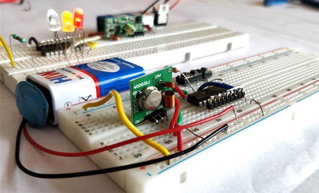
Power both the Breadboards and you should notice that the LEDs will start glowing. Now press any button on the transmitter breadboard and the respective LED will be turned off in the receiver circuit.
This is because the push button pins (D8-D11) are pulled up internally by the Encoder IC. Hence all the three LEDs will glow and when we press a button the data pin is connected to ground and so the respective LED on receiver side will be turned off.
The complete working can be seen at the video given below. However I have used only 3 LED for demonstration purpose you can use four as well. You can also connect Relay in place of LEDs and then you can control AC appliances wirelessly using RF Remote. Hope you understood the project and enjoyed building one. If you have any doubts post them in the comment section below or on the forum and I will be happy to help you out.
Comments
Thanks Rajdeep,
Thanks Rajdeep,
To make the LED turn on only when the button is pressed, you can either use a push button which is of NC (normally closed type) or use a PNP transistor like BC557 at the receiver side. The base of the transistor should be connected to decoder pin through a resistor and the load (LED) should be closed through the collector and emitter.
Can you give me diagram. Bcz
Can you give me diagram. Bcz I m new in this
Sir can you explain this
Sir can you explain this again and please if it is possible give me diagram.
Sir, my module has 4 pins (,i
Sir, my module has 4 pins (,i.e., one antenna pin) So how to make an antenna?
And I am trying to make it without using encoder/decoder. So I proceeded like this ->
Transmitter = one terminal of push button to data and the other terminal to the ground wire.
Receiver = all the VCC pins connected to + (from 7805) & all the GND to —. Now I've connected one 470 ohm resistor with LED (similar to your diagram). One terminal is grounded. But the data pin, I'm confused on which data pin to use. Shall I join both data pins or use any one or NC??
Is my approach all okay?
Yes go ahead!
You can join both the data pins and proceed with the project. However a circuit diagram of your connection would enable me to help you better.
Hi Gabriel,
Hi Gabriel,
What do you mean by 8 channel? Are you trying to control 8 outputs on the receiver side? If yes then you have to use some digital IC or MCU on the output side of Decoder IC. We will get 4 bit of data using this 4 bit data we can control upto 2^4 =16 outputs
Which rf module I should use
Which rf module I should use to make it range to 2-3 km ???
If you need such long
If you need such long distance you can use ESP8266 (works on Wi-Fi) or GSM modules
Questions on RF MODULE
In my receiver circuit LEDs glow without giving power to transmitter and doesn't toggle to on and off.
Kindly reply.
Data pin confusion
Hi I just want to know when we power up both circuit then what is the default state (low or high) of data pins of decoder ic. Cause I want to make rf
Based robot so I need to know the default value of decoder ic data pins after that I can make my program code for the robot.
Sir your explanation was too
Sir your explanation was too good and i have a doubt, once we transmit data if we connect the output to Arduino instead of led’s. Will a Arduino store it in buffer for further processing because i need this in my project.
receiver circuit 4 channel relay board connection
Dear friend
I have connected the 4 channel relay in the receiver circuit insted of your LED, But due insificient grounding relay not getting on i have used mobile charger circuit for power of the relay & receiver circuit, so how can i solve this problem.
i m stucked now, pl help me.
I cant completely understand
I cant completely understand your problem!! Try replacing the relay with Led and check if that is working.
A circuit diagram would help to debug
Making a RF module with just 2 LEDs
How can I make a RF module with just 2 LEDs?
Follow the same tutorial
Follow the same tutorial remove one LED, as simple as that
hi and thanks for project.
hi and thanks for project.
can i replace pt2262 and pt2272-m4 ic instead of ht12e ?
what will happen if i push
what will happen if i push all 3 buttons at once?
Hey, I am trying to do your
Hey, I am trying to do your project, but it aint working for me. Could it be because of such a huge 470k oscilator resistor? Datasheet says if encoders resistor is 1M, then, decoders should be around 50k? not 470k
I used 470 and it worked fine
I used 470 and it worked fine for me. The problem could more likely be with your connections. Use a multimeter and check for continuity for all pins.
reciever pin count
Why does your circuit diagram show 8 pins for the receiver, when the photos of the receiver only show 4 pins?
In circuit diagram each pin
In circuit diagram each pin is shown twice, you can use any one of these two sets of pins. But in hardware (mostly) you will have only one set of pins
Can i use zener diode instead
Can i use zener diode instead of 7805
and canyou tell me how long the distance?
Transmission of a voltage value
Can this sytem be modified to transmit a dc voltage such as the output of a thermister and the reciever module output this to a display????
Thanks
Greg
how can i controll ac load
how can i controll ac load with this circuit
What kind of relay voltage…
What kind of relay voltage is available if I choose to make the feed that would have powered the LEDs to go to a relay instead?

Thanks for the great explanation...
I had one doubt that if instead of powering the led's right from the beginning what if we wanted to power the LED only when a particular push button was pressed... In that case what will be the change in the circuit required?