

This is our 10th tutorial of Learning PIC microcontrollers using MPLAB and XC8. Till now, we have covered many basic tutorials like LED blinking with PIC, Timers in PIC, interfacing LCD, interfacing 7-segment, ADC using PIC etc. If you are an absolute beginner, then please visit the complete list of PIC tutorials here and start learning.
In this tutorial, we will learn How to generate PWM signals using PIC PIC16F877A. Our PIC MCU has a special module called Compare Capture module (CCP) which can be used to generate PWM signals. Here, we will generate a PWM of 5 kHz with a variable duty cycle from 0% to 100%. To vary the duty cycle we are using a potentiometer, hence it is recommended to learn ADC tutorial before starting with PWM. PWM module also uses timers to set its frequency hence learn how to use timers beforehand here. Further, in this tutorial we will use a RC circuit and a LED to convert the PWM values to Analog voltage and use it for dimming the LED light.
What is a PWM Signal?
Pulse Width Modulation (PWM) is a digital signal which is most commonly used in control circuitry. This signal is set high (5v) and low (0v) in a predefined time and speed. The time during which the signal stays high is called the “on time” and the time during which the signal stays low is called the “off time”. There are two important parameters for a PWM as discussed below:
Duty cycle of the PWM:
The percentage of time in which the PWM signal remains HIGH (on time) is called as duty cycle. If the signal is always ON it is in 100% duty cycle and if it is always off it is 0% duty cycle.
Duty Cycle =Turn ON time/ (Turn ON time + Turn OFF time)
Frequency of a PWM:
The frequency of a PWM signal determines how fast a PWM completes one period. One Period is complete ON and OFF of a PWM signal as shown in the above figure. In our tutorial we will set a frequency of 5KHz.
PWM using PIC16F877A:
PWM signals can be generated in our PIC Microcontroller by using the CCP (Compare Capture PWM) module. The resolution of our PWM signal is 10-bit, that is for a value of 0 there will be a duty cycle of 0% and for a value of 1024 (2^10) there be a duty cycle of 100%. There are two CCP modules in our PIC MCU (CCP1 And CCP2), this means we can generate two PWM signals on two different pins (pin 17 and 16) simultaneously, in our tutorial we are using CCP1 to generate PWM signals on pin 17.
The following registers are used to generate PWM signals using our PIC MCU:
- CCP1CON (CCP1 control Register)
- T2CON (Timer 2 Control Register)
- PR2 (Timer 2 modules Period Register)
- CCPR1L (CCP Register 1 Low)
Programming PIC to generate PWM signals:
In our program we will read an Analog voltage of 0-5v from a potentiometer and map it to 0-1024 using our ADC module. Then we generate a PWM signal with frequency 5000Hz and vary its duty cycle based on the input Analog voltage. That is 0-1024 will be converted to 0%-100% Duty cycle. This tutorial assumes that you have already learnt to use ADC in PIC if not, read it from here, because we will skip details about it in this tutorial.
So, once the configuration bits are set and program is written to read an Analog value, we can proceed with PWM.
The following steps should be taken when configuring the CCP module for PWM operation:
- Set the PWM period by writing to the PR2 register.
- Set the PWM duty cycle by writing to the CCPR1L register and CCP1CON<5:4> bits.
- Make the CCP1 pin an output by clearing the TRISC<2> bit.
- Set the TMR2 prescale value and enable Timer2 by writing to T2CON.
- Configure the CCP1 module for PWM operation.
There are two important functions in this program to generate PWM signals. One is the PWM_Initialize() function which will initialize the registers required to set up PWM module and then set the frequency at which the PWM should operate, the other function is the PWM_Duty() function which will set the duty cycle of the PWM signal in the required registers.
PWM_Initialize()
{
  PR2 = (_XTAL_FREQ/(PWM_freq*4*TMR2PRESCALE)) - 1; //Setting the PR2 formulae using Datasheet // Makes the PWM work in 5KHZ
    CCP1M3 = 1; CCP1M2 = 1;  //Configure the CCP1 module
    T2CKPS0 = 1;T2CKPS1 = 0; TMR2ON = 1; //Configure the Timer module
    TRISC2 = 0; // make port pin on C as output
}
The above function is the PWM initialize function, in this function The CCP1 module is set to use PWM by making the bit CCP1M3 and CCP1M2 as high.
The timer module’s prescaler is set by making the bit T2CKPS0 as high and T2CKPS1 as low the bit TMR2ON is set to start the timer.
Now, we have to set the Frequency of the PWM signal. The value of the frequency has to be written to the PR2 register. The desired frequency can be set by using the below formulae
PWM Period = [(PR2) + 1] * 4 * TOSC * (TMR2 Prescale Value)
Rearranging these formulae to get PR2 will give
PR2 = (Period / (4 * Tosc * TMR2 Prescale )) - 1
We know that Period = (1/PWM_freq) and Tosc = (1/_XTAL_FREQ). Therefore.....
PR2 = (_XTAL_FREQ/ (PWM_freq*4*TMR2PRESCALE)) – 1;
Once the frequency is set this function need not be called again unless and until we need to change the frequency again. In our tutorial I have assigned PWM_freq = 5000; so that we can get a 5 KHz operating frequency for our PWM signal.
Now let us set the duty cycle of the PWM by using the below function
PWM_Duty(unsigned int duty)
{
      if(duty<1023)
  {

    duty = ((float)duty/1023)*(_XTAL_FREQ/(PWM_freq*TMR2PRESCALE)); // On reducing //duty = (((float)duty/1023)*(1/PWM_freq)) / ((1/_XTAL_FREQ) * TMR2PRESCALE);
    CCP1X = duty & 1; //Store the 1st bit
    CCP1Y = duty & 2; //Store the 0th bit
    CCPR1L = duty>>2;// Store the remining 8 bit
  }
}
Our PWM signal has 10-bit resolution hence this value cannot be stored in a single register since our PIC has only 8-bit data lines. So we have use to other two bits of CCP1CON<5:4> (CCP1X and CCP1Y) to store the last two LSB and then store the remaining 8 bits in the CCPR1L Register.
The PWM duty cycle time can be calculated by using the below formulae:
PWM Duty Cycle = (CCPRIL:CCP1CON<5:4>) * Tosc * (TMR2 Prescale Value)
Rearranging these formulae to get value of CCPR1L and CCP1CON will give:
CCPRIL:CCP1Con<5:4> = PWM Duty Cycle / (Tosc * TMR2 Prescale Value)
The value of our ADC will be 0-1024 we need that to be in 0%-100% hence, PWM Duty Cycle = duty/1023. Further to convert this duty cycle into a period of time we have to multiply it with the period (1/ PWM_freq)
We also know that Tosc = (1/PWM_freq), hence..
Duty = ( ( (float)duty/1023) * (1/PWM_freq) ) / ( (1/_XTAL_FREQ) * TMR2PRESCALE) ;
Resolving the above equation will give us:
Duty = ( (float)duty/1023) * (_XTAL_FREQ / (PWM_freq*TMR2PRESCALE));
You can check the complete program in the Code section below along with the detailed Video.
Schematics and Testing:
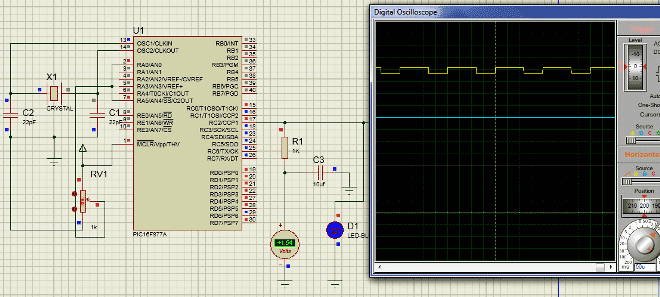
As usual let us verify the output using Proteus simulation. The Circuit Diagram is shown below.

Connect a potentiometer to 7th pin to feed in a voltage of 0-5. CCP1 module is with pin 17 (RC2), here the PWM will be generated which can be verified using the Digital oscilloscope. Further to convert this into a variable voltage we have used a RC-filter and an LED to verify the output without a scope.
What is a RC-Filter?
An RC filter or a Low pass filter is a simple circuit with two passive elements namely the resistor and the capacitor. These two components are used to filter the frequency of our PWM signal and make it a variable DC voltage.
If we examine the circuit, when a variable voltage is applied to the input of R, the capacitor C will begin to charge. Now based on the value of the capacitor, the capacitor will take some time to get fully charged, once charged it will block the DC current (Remember capacitors block DC but allows AC) hence the input DC voltage will appear across the output. The high frequency PWM (AC signal) will be grounded through the capacitor. Thus a pure DC is obtained across the capacitor. A value of 1000Ohm and 1uf was found to be appropriate for this project. Calculating the values of R and C involves circuit analysis using transfer function, which is out of scope of this tutorial.
The output of the program can be verified using the Digital Oscilloscope as shown below, vary the Potentiometer and the Duty cycle of the PWM should change. We can also notice the output voltage of the RC circuit using the Voltmeter. If everything is working as expected we can proceed with our hardware. Further check the Video at the end for full process.
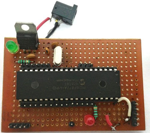
Working on Hardware:
The hardware setup of the project is very simple, we are just going to reuse our PIC Perf board shown below.
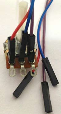
We will also need a potentiometer to feed in the analog voltage, I have attached some female end wires to my pot (shown below) so that we can directly connect them to the PIC Perf board.
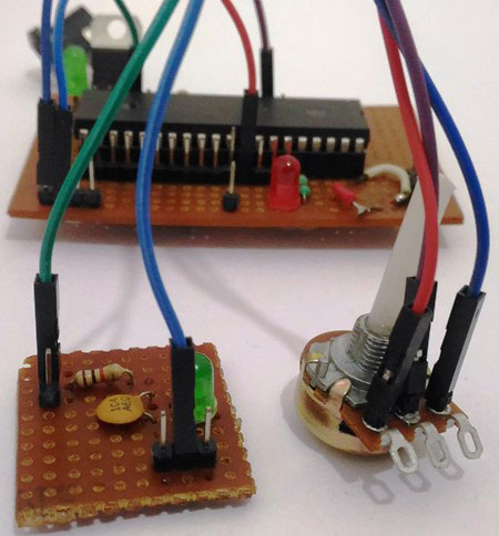
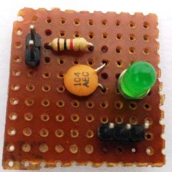
Finally to verify the output we need a RC circuit and a LED to see how the PWM signal works, I have simply used a small perf board and soldered the RC circuit and the LED (to control brightness) on to it as shown below
We can use simple female to female connecting wires and connect them according to the schematics shown above. Once the connection is done, upload the program to the PIC using our pickit3 and you should be able to get a variable voltage based on the input of your potentiometer. The variable output is used to control the brightness of the LED here.
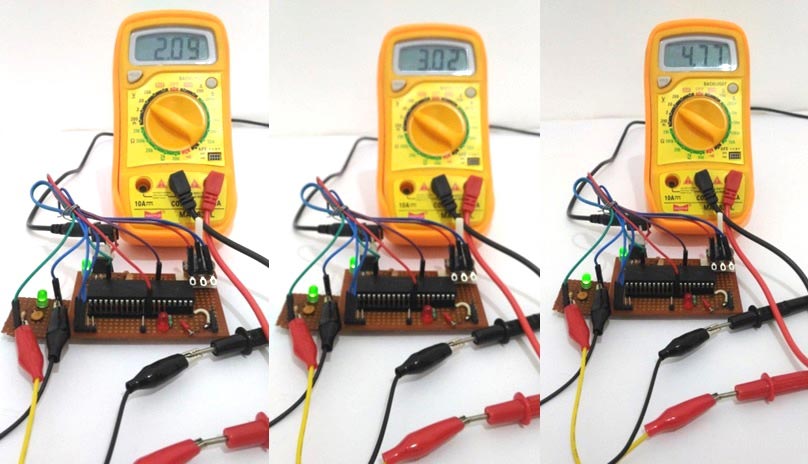
I used my multimeter to measure the variable outputs, we can also notice the brightness of the LED getting changed for different voltage levels.
That’s it we have programmed to read the Analog voltage from the POT and convert into PWM signals which in turn have been converted into Variable voltage using RC filter and the result is verified using our hardware. If you have some doubt or get stuck somewhere kindly use the comment section below, we will be happy to help you out. The complete working is working in the video.
Also check our other PWM Tutorials on other microcontrollers:
Complete Project Code
// CONFIG

#pragma config FOSC = HS        // Oscillator Selection bits (HS oscillator)

#pragma config WDTE = OFF       // Watchdog Timer Enable bit (WDT disabled)

#pragma config PWRTE = ON       // Power-up Timer Enable bit (PWRT enabled)

#pragma config BOREN = OFF      // Brown-out Reset Enable bit (BOR disabled)

#pragma config LVP = ON         // Low-Voltage (Single-Supply) In-Circuit Serial Programming Enable bit (RB3/PGM pin has PGM function; low-voltage programming enabled)

#pragma config CPD = OFF        // Data EEPROM Memory Code Protection bit (Data EEPROM code protection off)

#pragma config WRT = OFF        // Flash Program Memory Write Enable bits (Write protection off; all program memory may be written to by EECON control)

#pragma config CP = OFF         // Flash Program Memory Code Protection bit (Code protection off)
#define _XTAL_FREQ 20000000

#define TMR2PRESCALE 4
#include <xc.h>
long PWM_freq = 5000;
PWM_Initialize()

{

  PR2 = (_XTAL_FREQ/(PWM_freq*4*TMR2PRESCALE)) - 1; //Setting the PR2 formulae using Datasheet // Makes the PWM work in 5KHZ

    CCP1M3 = 1; CCP1M2 = 1;  //Configure the CCP1 module

    T2CKPS0 = 1;T2CKPS1 = 0; TMR2ON = 1; //Configure the Timer module

    TRISC2 = 0; // make port pin on C as output

}
PWM_Duty(unsigned int duty)

{

      if(duty<1023)

  {
    duty = ((float)duty/1023)*(_XTAL_FREQ/(PWM_freq*TMR2PRESCALE)); // On reducing //duty = (((float)duty/1023)*(1/PWM_freq)) / ((1/_XTAL_FREQ) * TMR2PRESCALE);

    CCP1X = duty & 1; //Store the 1st bit

    CCP1Y = duty & 2; //Store the 0th bit

    CCPR1L = duty>>2;// Store the remining 8 bit

  }

}
void ADC_Initialize()

{

  ADCON0 = 0b01000001; //ADC ON and Fosc/16 is selected

  ADCON1 = 0b11000000; // Internal reference voltage is selected

}

unsigned int ADC_Read(unsigned char channel)

{

  ADCON0 &= 0x11000101; //Clearing the Channel Selection Bits

  ADCON0 |= channel<<3; //Setting the required Bits

  __delay_ms(2); //Acquisition time to charge hold capacitor

  GO_nDONE = 1; //Initializes A/D Conversion

  while(GO_nDONE); //Wait for A/D Conversion to complete

  return ((ADRESH<<8)+ADRESL); //Returns Result

}
void main()

{

    int adc_value;

  TRISC = 0x00; //PORTC as output

  TRISA = 0xFF; //PORTA as input

  TRISD = 0x00;

  ADC_Initialize(); //Initializes ADC Module

  PWM_Initialize();  //This sets the PWM frequency of PWM1
  do

  {

    adc_value = ADC_Read(4); //Reading Analog Channel 0

    PWM_Duty(adc_value);


      __delay_ms(50);


  }while(1); //Infinite Loop


}
Comments
Please explain you requirement in detail
Hi Arkan,
imple practical circuits about (delay time cct) in my work (electronic change over equipment) so as to make more safity in the work
Kindly explain your requirements in detail, we will be happy to help you out!!
And I would like to thank you very much about all these informatios
thank you very much
Thanks Arkan, your comments encourage us..
Hi. I am writing a PWM code
Hi. I am writing a PWM code for PIC18f4550 micrcocontroller. I am using MPLAB X IDE with XC8. I am referring to your code to write a simple PWM code to test it on oscilloscope and later on build on it to do more things. I don't understand what are:
CCP1X = duty & 1; //Store the 1st bit
CCP1Y = duty & 2; //Store the 0th bit
What are CCP1X and CCP1Y? What is their role?
CCP1X and CCP1Y usage description!!
Hi Ann,
I will explain the following lines from my code
CCP1X = duty & 1; //Store the 1st bit
CCP1Y = duty & 2; //Store the 0th bit
CCPR1L = duty>>2;// Store the remining 8 bit
As you can see the variable duty contains the value of the PWM duty cycle. This va;ue has to be used to set the CCP1X and CCP1Y bit and also the CCPR1L register.
The following lines are from the datasheet
The PWM duty cycle is specified by writing to the
CCPR1L register and to the CCP1CON<5:4> bits. Up
to 10-bit resolution is available. The CCPR1L contains
the eight MSbs and the CCP1CON<5:4> contains the
two LSbs.
CCP1CON<5:4> is nothing but the CCP1X and CCP1Y bits respectively. The value of duty after this formulae(shown below) can be upto 10-bit resolution
duty = ((float)duty/1023)*(_XTAL_FREQ/(PWM_freq*TMR2PRESCALE));
Since the Registers in our PIC MCU can hold only upto 8-bits(PIC16F877A is a 8-bit MCU) the additional two bits (CCP1X and CCP1Y) are used to store the least two significant bits and the remaining 8 bits are stored into the CCPR1L register.
Hope this answered your question.
Confusion in order of bit masking
Hi
I was just wondering about the order of bit masking for the 0th and the 1st bit of the duty cycle to store in the CCP1X and CCP1Y locations. So actually, CCP1X should be storing the 1st bit of duty cycle and the CCP1Y should be containing the 0th bit right and it is commented like that also. I am pasting the code below for reference
CCP1X = duty & 1; //Store the 1st bit
CCP1Y = duty & 2; //Store the 0th bit
CCPR1L = duty>>2;// Store the remining 8 bit
But to get the 0th bit in CCP1Y, duty should be done '& (AND)' with '1' right? and for getting 1st bit in CCP1X duty should be done '&' with '2' right? instead of the other way done above.
Thanks
I agree with Subil that 1st
I agree with Subil that 1st bit would be duty &2 and 0th bit would be duty &1
However, CCP1X and CCP1Y are ** bits ** whereas duty & 2 will evaluate to either 0 (binary 00) or 2 (binary 10)
and so you need to right shift duty & 2 before assigning to CCP1X
like this:
CCP1X = (duty & 2) >> 1; //Store the 1st bit
CCP1Y = duty & 1; //Store the 0th bit
can I use same code for
can I use same code for pic18f4550 or Do I need to do some changes????
Doubt in AC Fan controlling
Hi,
I checked your code for my project and it worked well. now the problem is only the led is dimming but the fan or bulb doesn't dimming. Help me in this.
What is your Driver circuit?
Hi Thejo,
Glad that the code worked for you...
I am not sure how you have interfaced the fan or bulb with the PIC MCU. Let me know what your driver circuit is. If you have used a relay it will not work. Hence make sure you use a power electronic device like MOSFET and you switch it properly using the PWM signals.
hello! please from ''duty = (
hello! please from ''duty = ((float)duty/1023)*(_XTAL_FREQ/(PWM_freq*TMR2PRESCALE)); ''' what is ''float'' doing in there? is it a variable or what??
why did you hav to add float to the formulae??
No Float is not a variable.
No Float is not a variable.
Here the data type of duty is integer. So when this integer value is devided by 1023 it will also be an integer. But we need it in terms of decimal for better accuracy. So we prefix (float) to ask the compilernot to truncate the obtained result to interger but keep it in float as such.
Hope this clears your doubt.
Thanks,
Aswinth
please give me an example of
please give me an example of this... am a bit confuse.. from PWM_Duty(adc_value); i understand that, voltage from 0-5v will also be converted from 0-1023
take for instance adc_value=1020 which in our duty formulae has been divided by 1023.duty=((float)duty/1023) saying (1020/1023)=0.9971 which will result everything to be zero.. so please explain to me how (float) works in that code with an example of duty result between 0-5v.. Thank you!(i want to move to the next tutorial after getting full understanding of this)
Yes you got it partially
Yes you got it partially correct.
(1020/1023)=0.9971
But, the value 0.9971 will not be converted to 0 yet. Because we still have the remaning formulae to complete.
so,
(duty/1023) * (20000000/(5000*4))
Since you took an example of 1020 as duty
0.9971 * (20000000/(5000*4)
Which will be 0.9971*(1000) = 997
PWM_Duty(997);
Hope this clears things for you
Yes, you can...
Yes, you can...
Interface a keyboard with microcontroller and read the entered values. Then write that value to PWM_duty() function. This way you should be able to control the Servo motor based on your entered value.
can you help me?
iam intersted this pwm generating ckt.
first of all i thanks you lot about this tutorials .
can you help me how to modify this ckt instead of pot. make it digital through Up & Down push buttons.... is it possible?
Yes it is possible with some tweaks in code
Hi Kumar,
Yes, it is very much possible. Here in this code above. The variable adc_value controls the duty cycle of the output PWM signal. You simply have to connect two push buttons and use some If statements to check if they are pressed. If pressed simply increment/decrement the value of adc_value. note the range of this variable should only be from 0-1024
pwm for pic16f18857
Hi,
This code is very helpful to get the basic idea for coding for a pwm output.
Can you guide me to design a pwm output for pic16f18857.
Thanks
hhow do i make this run for
hhow do i make this run for pic16f18857
The method is the same. Only
The method is the same. Only the name of registers might change. Read the datasheet of PIC16F18857 and modify the code accordingly
help needed
hi sir
,
this project helped me.
nice and great......
but
i want to make this project on mickro c compiler..plz..pic16f877a
Hi,
Hi,
I am using a PIC16F873A with a variation of your code that uses a for() loop to increase and decrease the duty cycle. I am using a LED component that effectively has RGB LED's, connected to PORTC 1, 2, and 3. Is there any way of changing which pin the pwm signal outputs on? have tried altering the TRISC2=0 to TRIS1=0 etc to no avail. is it possible to output the signal on multiple pins at the same time?
PWM config.
Hello!
Never have I used PWM signals before so it's kinda tricky to me. I am using PIC18F8722 and am supposed to build a function with the following structure : void config_PWM(int en, int ch, int freq, int period, int c_duty) . //en=enable the module, ch=PWM output channel, freq=osc. freq., period=PWM period(0-127), c_duty=cycle duty(0-1024) .
All the information here has been really helpful, I am just having difficulties in putting all this stuff together within one function. If you could please land me a hand I would be very grateful, since I won't have access to the microcontroller til next week. Thank you!
If I may ask, why is the
If I may ask, why is the signal from the potentiometer being fed to both RA0 and RA5 ?
Thanks
Sorry for the mistake CB, you
Sorry for the mistake CB, you can connect it either to RA0 or to RA5, the code here reads voltage from pin RA5. So if you are using this code then you can ignore the connection to RA0
Ur ckt and code working fine
Ur ckt and code working fine for led only ang it also getting dimmed. But even after adding a TRIAC the bulb/ fan not getting on. Please suggest?
sir, how do i control ac
sir, how do i control ac loadinstead of led.....
nice job man
nice job man ! i did this with PIC16F628A and works great , i just need to change TRISC2 TO TRISB9 and the pic16 used don't have ADC
Ur ckt and code working fine
Ur ckt and code working fine for led only ang it also getting dimmed. But even after adding a TRIAC the bulb/ fan not getting on. Please suggest?
You cannot drive all types of
You cannot drive all types of TRIAC directly with PIC, the reason is they might consume more current than LED. Look for triac driving circuit
Can I generate a 10MHz frequency at 50% duty cycle using the PIC
Can I generate a 10MHz frequency at 50% duty cycle using the PIC16F628A
Power Electronics
Sir can you tell me what will be the possible changes in the code if I use a 4Mhz crystal for generating a PWM frequency of 250hz?
generating pwm with ECCP (enhanced capture/compare/pwm)
hello i am currently working on generating pwm with ECCP mode where my P1A and P1D switch at the same time also P1B and P1C also switch at the same time
the switching of P1A and P1D will always be reciprocal to that of P1B and P1C ,
which while P1A and P1D are on, P1B and P1C will be off and vice versal
in a nutshell am using that to generate a sinewave
so my question is that, is there any way i can configure the EECP to make P1A and P1C totally off
while P1B and P1D will be switching together as pwm?

Hi sir,
I am electrical engineering and I need more simple practical circuits about (delay time cct) in my work (electronic change over equipment) so as to make more safity in the work
Asimple practical cct please
And I would like to thank you very much about all these informatios
thank you very much
Arkan M R .