
This automatic staircase light circuit switch on the staircase lights automatically when someone enters on the stairs and gets off after some time. There are two important components in this circuit, first is PIR Sensor (Passive Infrared Sensor) and second is Relay.
PIR Sensor
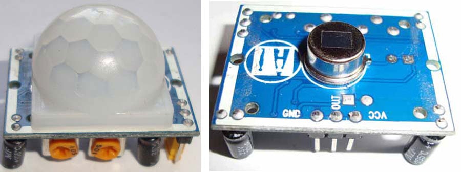
PIR sensor is used here to detect the Human body movement, whenever there is any body movement the voltage at output pin changes. Basically it detects the Change in Heat, and produce output whenever such detection occurs. You can learn more about PIR sensor here, there are some useful features in PIR sensor like how to change the distance range, how to set the duration for which the light should be ON etc.
Also check: Automatic Staircase light using AVR Microcontroller
Relay
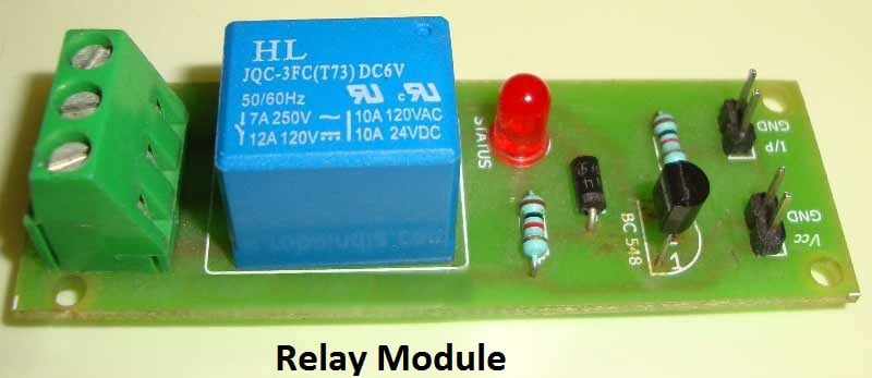
Relay is an electromagnetic switch, which is controlled by small current, and used to switch ON and OFF relatively much larger current. Means by applying small current we can switch ON the relay which allow much larger current to flow. Relay is the good example of controlling the AC (alternate current) devices, using a much smaller DC current. Commonly used Relay is Single Pole Double Throw (SPDT) Relay, it has five terminals as below:
When there is no voltage applied to the coil, COM (common) is connected to NC (normally closed contact). When there is some voltage applied to the coil, the electromagnetic field produced. Which attract the Armature (lever connected to spring), and COM and NO (normally open contact) gets connected, which allow larger current to flow. Relays are available in many ratings, here we used 6V operating voltage relay, which allow 7A-250VAC current to flow.
Relay is configured by using a small Driver circuit which consist a Transistor, Diode and a resistor. Transistor is used to amplify the current so that full current (from the DC source – 9v battery) can flow through coil to fully energies it. Resistor is used to provide biasing to transistor. And Diode is used to prevent reverse current flow, when the transistor is switched OFF. Every Inductor coil produces equal and opposite EMF when switched OFF suddenly, this may cause permanent damage to components, so Diode must be used to prevent reverse current. A Relay module is easily available in the market with all its Driver circuit on the board or you can create it by using above components. Here we have used 6V Relay module.
Circuit Explanation

This automatic staircase light circuit can be easily explained. Whenever PIR sensor detects any body movement, its OUTPUT pin becomes HIGH, which applies the triggering voltage to the base of the transistor, transistor get ON, and current started flowing through the coil. Coil in Relay gets energies and create electromagnetic field, which attracts the lever and COM and NO get connected. This allows a much larger current (220v AC) to flow, which turns ON the BULB. You can increase or decrease the Bulb ON duration by setting up PIR sensor.
Comments
sir,may i know what kind of
sir,may i know what kind of bulb u have used is it led bulb or regular zero watt bulb.
What happens if i use a zero watt bulb ?
Sir, I kindly request u to send me the clear picture of the connection because i am not understanding the PIR and the relay module connection from the above picture...THANK YOU..
Yes, you can use zero watt
Yes, you can use zero watt bulb. You can use any AC mains home appliances. Circuit diagram is already very clear, further you can check its Image at the top and Video at the end.
Automatic staircase light
Ya you can use any kind of bulb for this project.Because you are using a 220v supply to the relay so no problem
pir , motion sensor
Hey, I like this project but
what type of relay module u r using ,
And if we use it in real it will work, or it will fuse after using for days
Please reply,
This is a simple Relay module
This is a simple Relay module, if you dont have it, you can use simple Relay with resistors and diode, as shown in Circuit Diagram. Yes, it can work for long time.
Question
Great content! I'm new to this world of electronics so I hope my questions are not too annoying. This circuit scares me a bit because I'm used to working with 9v, 6v, and less. This circuit diagram shows to hook up a 220v ac in series with a 9v dc battery. Clearly I am not understanding this correctly. Please advise what I need to read to correct my understanding.
No, its not in series, please
No, its not in series, please look carefully. Wires joints are represented by Dots. Please be extra careful while working with AC mains, it can be lethal.
pir circuit
@Mr Tiger - you are mistaking the intersection points of the line going from B1 to VCC are connected to the 220v.
There's no easy way to draw it where the lines cross. As a check, if you imagine that the B1 to VCC line was removed, you can clearly see the DC side is separate fron the AC side.
success
I made this circuit this morning using components I already own. It was pretty cool to see it work. Thank you for sharing. For the sensor, and circuit I used 5.12 dc v(atm, my only steady power supply), and for the light source I used (9v battery, 330 Ohm, LED) because I fear an early death.
Can we use this for office
Can we use this for office light in retriggering mode,if person is in its area would it continue working or switch it On/off continuously?
Yes, it can be used in Re
Yes, it can be used in Re-triggering mode to keep the Light ON, until some movement is there. Check this to learn more about PIR sensor.
may i ask this one using
may i ask this one using coding or not? like arduino or PLC ?
No coding, it is just a
No coding, it is just a simple circuit without any micro controller.
Not Working
i have made this And Not Working :( please Anyone Help me
Is it possible to add delay.
Hi,
Is it possible to add more delay to this ?
Because it will look very odd to switch the lights immediately.
Thanks,
Kishore.
Then you need to use
Then you need to use Microcontroller to add some delay after PIR detect any motion.
Where can I get pir sensor
Where can I get pir sensor
Are they sold or they are built
electronic
I want to build a transformerless power suply.Please help me and some suggestion
Check this Circuit:
Check this Circuit: Transformerless Power Supply
PIR Sensing and Delay Time
Dear Concern,
I am working your project. which you have show is very much interesting. But my question is when one object is detected the how can i set long time as long as the object is present of that room then when the object is not in room then sensor will stop the supply.
Thank in advanced
hi. how did u make it glow as
hi. how did u make it glow as long as there is a person and switch off when the person goes out of the room?
Please send me the circuit diagram and the working.
How to connect LDR with this circuitn
Dear Concern,
I have got the delay answer what i mention in my previous post.
Now my question is , how do i connect LDR with the above circuit so that when there is dark on the room the light glow.
Thanks in advanced
Check these circuits: Dark
Check these circuits: Dark Detector using LDR and 555 Timer IC and Dark Detecting LED
it is not working help needed
hi i dont know why but my project is not working i tried my best
i saw all the connection
i just did not put the relay module because i was not able to find it so i made the circuit as it was made in the digram still it does not work my light gets on but does not get closed wat do you thing wat will be the problem plz let me know plz help me sir plz and reply me as soon as possible plz some one help me i need help
You need to adjust Time Delay
You need to adjust Time Delay Control Knob in PIR sensor, check this circuit to understand the PIR sensor: PIR Sensor Based Motion Detector/Sensor Circuit
PIR Motion Sensor switch
I purchased PIR Motion Sensor switch to fix in a room containing 9 small lights each 6 watt. So total load comes 54 watt. Motion switch indicates that it works up to maximum 1000 Watt. Please let me know if one switch will be enough to work for all nine lights. Moreover can we fix on/off switches to control individually.
yes you can trigger many
yes you can trigger many devices with one PIR, and power depends upon relay's rating. To control individual lights, use some microcontroller.
You don't mention R 2 on
You don't mention R 2 on circuit diagram and also not to mention green colour tuning at your circuit diagram but I have see clearly those item (R2&green colour tuning) soldering at your Relay module and you have to use Relay module to complete your project not to flow your mention circuit diagram so please clear my confusing since I'm not a professional electronic person or stodent.
instead of 6V Relay which one
instead of 6V Relay which one can I use?
Please help me
does this circuit keeps the
does this circuit keeps the light 'ON' whenever there is a human presence at its range? or does it turns off after some time?? I've made a motion detector which turns of after some time (obviously!). also, i want to use a PIR based circuit for automatic light for my room. by that, when ever i enter my room, the light should turn on automatically and it will be on till i leave my room. so can i use this circuit for the same?? please advice. thanks in advance. :)
Starter here, i wanna ask how
Starter here, i wanna ask how long does the bulb will lit up after a movement. Or it will turn off immediately if there's no more movement. Thank you in advance.
i make as all connection as per circuit diagram but my project n
i make as all connection as per given above circuit diagram but my project not work properly . The light is continiously blow
i can't find PIR sensor how
i can't find PIR sensor how can i have it
can i use tsop1738 sensor to
can i use tsop1738 sensor to replace ur own and use a tv remote
why use relay instead of a transistor, for switching?
Hello Sir/Madam,
I really liked the project. My professor asked me a question: Why are u using relays when transistors are much faster and long lasting? Relays are also electromagnetic sensitive.
I could not answer this question. I am definitely missing something. Please clarify my question.
Regards,
Deepti.
Relay is used to control AC
Relay is used to control AC appliances.
how long does the light glow for?
does the light remain on 'as long as' the person is there or does it switch off after a 'certain time' on its 'own'?
Sir...
Sir...
I wacth the video, in this video the light should automatically OFF after some seconds , when i used this CKT. In bathroom my the CKT. Dectet the motion and its ON (so, it will OFF in some seconds or it should ON till where should i was in bathroom ? ).
In this circuit, light will
In this circuit, light will remain On if there is continuous motion, otherwise it will switch off after some duration. you can control this duration, You can learn more about PIR sensor here,
I have done it but!!!!!!!!
Dear sir ,
I done this project as per diagram (as without relay module ,i connect relay switch)but my relay switch is countinuslly switching so plz solve it
Thank u.
Requirement of pcb layout
PLS SEND THE PCB LAYOUT ............
ON THE ABOVE EMAIL ID.
I WANT PCB LAYOUT OF Automatic Staircase Lights using PIR Sensor and Relay
about relay
sir , please tell me that can i use 5or 12v relay for ths project?
Yes you can use either 5V or
Yes you can use either 5V or 12V relay for this project.
Sir, i already follow the
Sir, i already follow the circuit diagram but my pir sensor does not working. Please I need your help.
Relay module always on
I am using a 5v relay module with red and green lights both are always on when I connect the battery. When I connect the light its on always and no effect from sensor. i tried keeping the sensor range to high and time to lowest nothing is happening. Please help.
Update to my query
The 5v relay module does not have a transistor (BC547) or the 1k resistor as in the picture. Hence connected them separately as per the circuit diagram and now its
working absolutely perfect.
connect LDR
When we enter in room at this time if room have all ready light then our circuit is not run but if it has darkness in room and we enter at this time room light is on...so we connect LDR but in which place in circuit we connect LDR ??????
You have to use an LRR along
You have to use an LRR along with a voltage comparator. The circuit will need major modifications.
Its not working properly how
Its not working properly how to connect the relay
in the circuit
Circuit not working
hi, i made connection according to you circuit diagram, but my relay is not turning on. when i connect led at place of realy then it work well . i tested all voltage by using DMM. when i connect led then Pir giver 3.5v or when i connect relay then pir sensor give 0.7v . due to 0.7v transistor not turning on. can you tell me where i am doing wrong or which is my part is not working.?
thanks in advance.
want to use it as a washroom light controller
I want to use it in my washroom. is it possible to raise its time limit when it activated with any motion and that put off.
if any washroom controlling ckt available. pls send me via my email ID.
Yes you can use it. The time
Yes you can use it. The time limit can be adjusted by just varying the potentiometer (yellow color) which is on the PIR sensor
Want this project to implement at my college labs.
Want this project to implement at my college labs. Will it work ? It should be durable and reliable.
Also I am confused first where to start from. Please guide me.
Start with something only
Start with something only then you will know where you have to be guided.. You can use the internet always
Also this is a very simeple
Also this is a very simeple circuit. You can easily get it done. So fear not and give it a try
pir sensor and switch circuit board
I am working on a project that would require the use of multiple infrared detectors. I would like to use 4 + mini detectors. I would like each detector to have a maximum range less than 4 inches, and a rather narrow sensing range. I do not understand what the three legs do on a detector do, I assume positive, negative, and output? Some say the output drops off, some have high output? I just want to have a number of sensors that when any one of them detects a warm blooded animal within a few inch proximity (almost contact) to send a signal to a switch which closes it so that the normally open switch closes allow the power to flow like the light bulb (for a set time, 1 second or so) so the next function will occur. I am sure this is out there somewhere but I am not studied at all in this type of circuitry. Any help appreciated.
Yes your project is very
Yes your project is very common and its already out there somewhere. Since you sound like a beginer and have 4 Motion sensors I would suggest you to use an Arduino so that things get a lot easy. One place where you should start with is
https://circuitdigest.com/microcontroller-projects/arduino-motion-detec…
To purchase
Staircases light automatically if ready made its ok or please give PCB and components give the rate
Can i modify the circuit diagram
Please, can i modify the circuit diagram by replacing the 9V to etA bridge rectifier and adding L7805 at the output before the resistor. Hope it will still work normally?

do you have any tutorial for this project from the start ?Sorry I'm beginner. Thanks in advance