
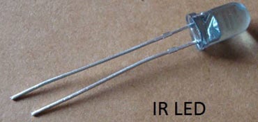
IR Transmitter and IR Receiver are commonly used to control electronic devices wirelessly, mainly through a remote. TV remotes and AC remotes are the best example of IR transmitters. TV generally consists of TSOP1738 as the IR receiver, which senses modulated IR pulses and convert them into electrical signal. Here in our circuit we are building IR remote and its receiver. We are using IR LED as transmitter and TSOP1738 as IR receiver.
How does IR LED Work?
IR LED emits infrared light, means it emits light in the range of Infrared frequency. We cannot see Infrared light through our eyes, they are invisible to human eyes. The wavelength of Infrared (700nm – 1mm) is just beyond the normal visible light. Everything which produce heat, emits infrared like our human body. Infrared have the same properties as visible light, like it can be focused, reflected and polarised like visible light.
Other than emitting invisible infrared light, IR LED looks like a normal LED and also operates like a normal LED, means it consumes 20mA current and 3vots power. IR LEDs have light-emitting angle of approx. 20-60 degree and range of approx. few centimetres to several feets, it depends upon the type of IR transmitter and the manufacturer. Some transmitters have a range in kilometers.
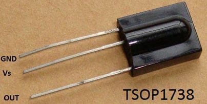
IR Receiver (TSOP17XX)
TSOP17XX receives the modulated Infrared waves and changes its output. TSOP is available in many frequency ranges like TSOP1730, TSOP1738, TSOP1740 etc. Last two digits represent the frequency (in Khz) of modulated IR rays, on which TSOP responds. Like for example TSOP1738 reacts when it receives the IR radiation modulated at 38Khz. Means it detects the IR which is switching On and Off at the rate of 38Khz. TSOP’s output is active low, means its output is remains HIGH when there is no IR, and becomes low when it detects IR radiation. TSOP operates on particular frequency so that other IRs in the environment can’t interfere, except the modulated IR of particular frequency. It has three pins, Ground, Vs (power), and OUTPUT PIN.
IR Transmitter Circuit Diagram
We are using TSOP1738 as IR receiver, so we need to generate the modulated IR of 38 kHz. You can use any TSOP, but you need to generate IR of respective frequency as TSOP. So we are using 555 timer in Astable mode to oscillate the IR at 38KHz frequency. As we know oscillation frequency of 555 timer is decided by resistor R1, R2 and capacitor C1. As you can see in the blow IR Transmitter Circuit We have used 1k R1, 20K R2 and 1nF capacitor to generate the frequency of approx. 38 KHz. It can be calculated using this formula: 1.44/((R1+2*R2)*C1).

Output Pin 3 of the 555 Timer IC has been connected to IR LED using 470 resistor and a push button switch. Whenever we press the button, circuit emits modulated IR at 38 KHz. A 100uF capacitor is connected across the supply to provide the constant supply to the circuit, without any ripple.
IR Receiver Circuit Diagram
IR Receiver circuit is very simple we just need to connect a LED to the output of the TSOP1738, to test the receiver. We have use BC557 PNP transistor here, to reverse the effect of TSOP, means whenever the output is HIGH LED will be OFF and whenever it detects IR and output is low, LED will be ON. PNP transistor behaves opposite to the NPN transistor, it acts as open switch when a voltage applied to its base and acts as closed switch when there is no voltage at its base. So normally TSOP output remains HIGH and Transistor behaves as open switch and LED will be OFF. As soon as TSOP detects Infrared, its output becomes low and transistor behaves as closed switch and LED will be ON. As you can see in the below IR receiver circuit A 10k resistor is used for provide proper biasing to transistor and a 470ohm resistor is used at LED for limiting the current. So whenever we press the Button at IR transmitter, it is detected by TSOP1738 and LED will glow.

We have further modified this circuit by using a relay to operate the AC mains appliances by an IR remote, in this remote controlled switch circuit. Check out our electronic circuits section to learn and build more interesting circuits and simple projects.
Comments
The code is as follow :
Option Explicit
Define uC as None
If ((Abukar sees an uC) == True) {
Echo "Houston, we have a problem !"
Echo "Please help Abukar to search for datasheets !"
}
Seriously !
Hi Daniel
Can you help me out with the following please. I need to show a diagram of a receiver of a door bell. the door bell receiver is supplied with 9 volt battery. when remote is activated the receiver sends the signal to the Buzzer and the Buzzer make sound.
Thank you buddy
regards
tony
Would it be possible to switch out from IR to some form of Bluetooth remote control?
This is completely a different circuit, you need to use Bluetooth module with some micro-controller to achieve this.
can you send this alarm circuit done without using any ic's
pls is there any circuit that can produce free energy? If you use up to 20 red led connected in series. I need the circuit diagram pls help.
Hello Dear
I was trying to work with TSOP1738. I used Attiny85 to generate IR signal. Receiver out put is fed to a simple transistor that drives a led. When circuit is switched on the receiver LED lights up for a brief period. The program is given below
void loop() {
for(i=0;i<50;i++){
digitalWrite(0,HIGH);
delayMicroseconds(13);
digitalWrite(0,LOW);
delayMicroseconds(13);
}
delayMicroseconds(500);
}
Pl help me to correct the mistake .
Sir can use ldr in the transmitter section that will power the circuit when dark( means when there is no light then the circuit will start emitting rays)
yes, you can use LDR as a switch, which turns on the Circuit in darkness. But for this purpose instead of using IR sensor, build it with 555 timer like here: Dark and Light Indicator Circuit
nice work sir,
pls help to make a audio transmitter and receiver above 60m range
Hi, I have two wire terminals. I need an IR controlled device to close the circuit (connect the terminals) ONLY when I command from a remote. How can we do this or how to modify the above circuitry to achieve this?
You can use Relay to close the circuit via Remote, check this circuit Remote Controlled Light Switch
Hi Abhishek, that's a good idea, thanks. I want one improvisation. I need the connection function like a calling bell arm. The moment I press the remote button, the receiver should connect and disconnect it when I release the button.Can I not connect the terminals in place of the LED per the current idea. It connects when remote button is pressed and disconnects when released?
Please can you email me a circuit diagram that produces IR signals at 38kHz.I have one that isn't working.
Sir,
Is it possible to work ir led and tsop using a single power supply?
Yes
Thanks maddy!!
But then how is it possible?
if i want to take the readings of tsop using arduino..
Can u suggest me a circuit in which both the tsop and irled use single powersource and the readings of tsop is measured by arduino.
I have tried one but once the reflection from irled occurs,the tsop output remail zero even when there is no reflection on to the tsop.
Please help me..
if we want to connect the output of the receiver circuit to the microcontroller can we directly do that by connecting just the output pin of the tsop to the microcontroller.
How do we transmit continuous IR pulses from IR Led without using the push button, but using the Arduino in place of the push button ?
sir....!!!instead of decoder (receiver )we can use microcontroller but how we integrated transmitter or what type of IC could we use instead of encoder transmitter
that can operated with microcontroller?
Leave the Transmitter part as it is, just change the receiver part according to your requirement.
howto increase or decrease the ir receiving range in ir receiver using tsop 1738 as i do not get any other receivers
You need to increase the range of Transmitter part, not receiver part. To increase the range, use convex lens at Tsop or use a powerfull IR LED
Really appreciate your work man, thank you. I have only one question, what is the emitor voltage for the Q1 transistor ?
Up to how much distance between sender and receiver it will work??
In my the LED stays on even when the transmitter is off
Check circuit at Receiver part, connect transistor BC557 properly.
Help. Anyone know where i can get the IR transmitters mentioned in the article that will work in the kilometer range? The usual places I order parts (Mouser, Digikey,etc) doesn't have anything close.
Sir, as per circuit diagram if press button prsent in transmitter circuit then IR led will glow and it will detected at IR receiver. But if i have multiple buttons at transmitter (e.g. matrix keyboard) then how can differentiate one button from another. Can is it possible to trasmitte addree of perticular button through IR Transreceiver ?
Yes you can decode the input from IR remote (tv/dvd remote), and can set the different functions on different button Press using some microcontroller, check this one: IR Remote Controlled Home Automation using Arduino
What is the maximum operable distance for this device to work efficiently?
If I require to transmit this code 0x25FC without microcontroller what I have to change or add to the transmitt circuit?
Use microcontroller, check this project to find out the IR Remote Hex code: Universal IR Remote Control using Arduino
why the led is blinking uneccessarily before giving the ir trigger in the receiver circuit
Im not understand well about pnp transistor or npn?
why if it is pnp transistor,why collector is in positive way? explain me plse if in this circyit we must reverse a transistor.
Circuit is correct, PNP transistor is used here because normally TSOP output remains HIGH and when it detects IR, the output becomes Low. This is clearly explained in the article.
Hello dear,
Can anyone tell me why we use capacitor in TSOP circuit
Hello sir
I have a problem regarding the receiver I use sliding switch instead of tact switch but when I switch on the transmitter for very long the led of the ir receiver will only stay for about 1 second how can i fix this?
anyone can you please tell me... the capacitor c1 of 1uF in the above ir receiver circuit is used for what purposed???
@Dheeraj @d. kupar: C1 is connected in receiver circuit for the same reason as we connected C3 100uF in Trasnmitter across the supply, to provide the constant supply without any ripple.
Hello creator, good job
Just please correct the wiring of the receiver part. The junction points are missing and the Q1 emitter is on the wrong side, connected this way, it will not work. Emitter to +5V, Collector to R2 ;-)
Circuit Diagram is correct and its a PNP transistor.
Sorry Maddy, it is really wrong.
PNP-transistor: the Emitter is connected to a more positiv voltage than the Collector
NPN-transistor the Collector is connected to a more positiv voltage than the Emitter
see also https://en.wikipedia.org/wiki/Bipolar_junction_transistor
Regards
Bernd
Maddy, are you sure? I agree with Bernd, it looks back-to-front. If the circuit is correct, could you explain how any current can ever flow through the transistor, please? With respect, I don't think the article is clear on this point.
Thanks, John
Really it is too useful for all students
I love this job
but I have a question
I have a device which used to scan invisible bar code. But now its not working at night but works day time. What's the problem. I can send its image if you please feel to help me out. Pls
do the circuit works perfectly at strong sunlight? i want a ir transmitter and receiver which works at sunlight ,so can u please refer me some other circuits....
Yes IR sensor get affected with sunlight, what kind of circuit do you want to build, we have lot of wireless circuits, just do search.
i have problem please help me,,,,,your some code delete please reply me my email address
If I were to have multiple transmitters with receivers in the same room all using the TSOP17xx's as receivers at different frequencies, do you think they would cross-talk? Are the frequencies too close together? I see a 30, 33, 36, 38, 40 and 56 kHz. Looking forward to using this for a fun project.
Yes they may interfere with each other, also check this project if you are interested in decoding IR signal of Remote: IR Remote Controlled Home Automation using Arduino
Can we use multiple switches from this circuit? If yes,then please mention tye circuit diagram.
You should use microcontroller for multiple switches: IR Remote Controlled Home Automation using Arduino
A friend gave a sat decoder. This decoder doesnt have a ir sensor insted it has a port named Display IR. how does it work, and can i fix an IR reciver?
IN IR RECEIVER CKT THE TRANSISTER CAN BE REMOVE BY USING OPPOSITE POLARITY OF LED
Hi, i have a tsop4838 receiver and a 6v supply and i want to use it to not blink a led but any switch other 6v device or a relais when i want to switch a separate powersupply.
It only has to respond when the reciever receives. it doesnt have to stay switched on or off.
So basically use it as a remote switch that only works when a button is pressed.
Check this one: Remote Controlled Light Switch
If i put an LED in series with ir led, should the LED flash at a frequency of 38khz?
It will flash but our eye can not detect this high frequency so LED will be appeared to be continuously glowing.
greetings m doing a mini project for opto electronics ,the project requires me to build a transmitter and receiver using a 555 timer,2* 120 ohm resistors,photo LED and TEPT 5600 photo transistor.
your help will be much appreciated.
i want to make a IR receiver to drive a relay.
i want to make similar IR receivers to drive different relays when different IR signals are given to it.
my budget is around so low. can you please help me?
this is such a great works.and i want to ask, how can i do to increase the frequency from 38kHz to reach up to 300GHz? is it possible to do that?your help will be much appreciated.tq
What if I've to use multiple transmitters and a single receiver using Arduino? How do we encode the IR LED output such that we can decide the codes at the receiver part by Arduino?
I used tsop38238 receiver and an arduino to check the receiver output(on serial monitor) using irRemote library. Each time the push button is pressed , different outputs were displayed. Why is it so?(Isn't it supposed to give the same pattern?).
Please send me long distance ir circuit diagram
Is it possible to use this circuit for a line follower robot?
In Line followers, photo diode is used to receive IR instead of TSOP, check this project: Line Follower Robot using Arduino
Hi, is there a way to amplify the IR led transmitter so that I can place the IR receiver(e.g TSOP17XX ) 2-3 meters apart from the IR led?
Please read the previous comments before asking, your question might has been already answered.
Hi...
Ur project lks osm
Can u please help me find where I can get a similar bread board presentation for ir people counter prepared using non programmable ic's please
Hi, I want to ask.
What simulation software you used in to create that IR tx/rx circuit? I have a problem when create in proteus. There is no component name TSOP1738.
Where can I get that component? Thanks
can we use bc547 instead of bc557?
How can I use IR sensor as distance measurement ?
can we decrease the distance between the sender and reciever about 1feet. tell me how can i do that
If anybody wants to operate a relay in the receiver what would be the circuit then?
Hi
It is possible to use multiple TSOP in this circuit. If yes, how?
Sir
Please i need a little clarification
How do i identify thy positive and negative sides of an op-amp
2-I know the ADC converts analog to digital signals on a PCB but i will love to know how the ADC actually relates with the input and output electrical components on an optical transceiver,on an optical receiver and on a transimpedance pcb
3-Can i use a UART/USART in conjuction with the op-amps in an optical receiver pcb
Kindly shed some light on this because most writs dont tell us how this actually relate on the pcn
After pressing the switch the LED blinks and stops even the button is being pressed.Can we make the LED on continuously by keeping the button pressed on?
You can keep the LED turned on by using a simple latching circuit, if you need more information check this out https://circuitdigest.com/electronic-circuits/simple-latch-circuit-diag…
Hi,
Just new to circuit digest. Wanting to build an IR 'fire and detect' circuit for an RC tank (tank fire and stationary or other tank detect). Searches led me to the article 'How to build an IR Transmitter and Receiver circuit using 555 timer'.
Will this do the job? What would the range be?
Thanks for any advice.
Tim

Hello dear.
bro can you help me to get the code of microC for this project İR Transmitter and reciever Thank you.
http://circuitdigest.com/electronic-circuits/ir-transmitter-and-receiver-circuit