
Building an indoor positioning system using ESP32 requires technology beyond GPS. While GPS trackers excel outdoors, indoor positioning system needs Ultra-Wideband (UWB) technology to achieve centimetre-level accuracy inside buildings. This guide shows you how to build a complete UWB indoor positioning system using the Qorvo DWM3000 UWB module with ESP32, capable of tracking devices with 10cm precision for UWB asset tracking and real-time location applications. That's fine for identifying buildings, but inadequate for precise UWB indoor localisation or UWB location tracking.
If you've ever tried tracking a device indoors with GPS, you know the limitations. GPS satellites 20,000 km away can't penetrate concrete, steel, and glass effectively. Even in semi-indoor spaces like warehouses or stadiums, GPS accuracy degrades to several meters. That's fine for identifying buildings, but inadequate for precise indoor navigation or asset tracking. If you are not looking for precise indoor tracking and would like to use GPS, then do check out our GeoLinker GPS Tracking Platform, which is a free, open-source tool from CircuitDigest for you to build, test, and deploy GPS projects seamlessly.
More recent applications, such as warehouse robotics, robotics in factories, UWB RTLS (real-time location systems) applications, airport navigation/tracking, and AR/VR, require indoor positioning systems that are fast and precise. Traditional technologies, such as Bluetooth and Wi-Fi, cannot deliver sub-meter accuracy with consistency; that's why this UWB positioning systems using ESP32 project focuses on the DWM3000 UWB positioning module and proven methodology. In this DIY UWB project we’ll show you how to set up an ESP32 indoor positioning system using the DWM3000 module and real-time visualization.

That's where Ultra-Wideband (UWB) comes in. Unlike GPS, UWB doesn't rely on satellites. Instead, it measures the time it takes radio pulses to travel between devices, achieving indoor positioning accuracy of down to 10 cm, allowing you to know exactly which chair you're sitting on, not just which room.
Table of Contents
- UWB vs Traditional Indoor Positioning Technologies
- Qorvo DWM3000
- How Does a UWB Indoor Positioning System Work?
- DWM3000 Capabilities
- Why UWB Technology Excels
- └ Other Qorvo UWB Modules
- Components Required
- Hardware Setup and Pin Connections
- From JSON Data to Real-Time Position
- ESP32 Tag Firmware Setup
- Real-Time Indoor Tracking Visualisation with Python
- Testing UWB Accuracy
- Future Upgrades
- GitHub Repository
Comparison: UWB vs Traditional Indoor Positioning Technologies
| Technology | Accuracy | Range | Best Use Case |
| UWB Positioning System | 10cm | Up to 200m | UWB asset tracking, UWB RTLS |
| Bluetooth | 1-3m | Up to 100m | Proximity detection |
| Wi-Fi | 5-15m | Up to 50m | Zone-level tracking |
| GPS | 5-10m | Global | Outdoor tracking only |
Qorvo DWM3000: The Core of Your UWB Indoor Positioning System Using ESP32
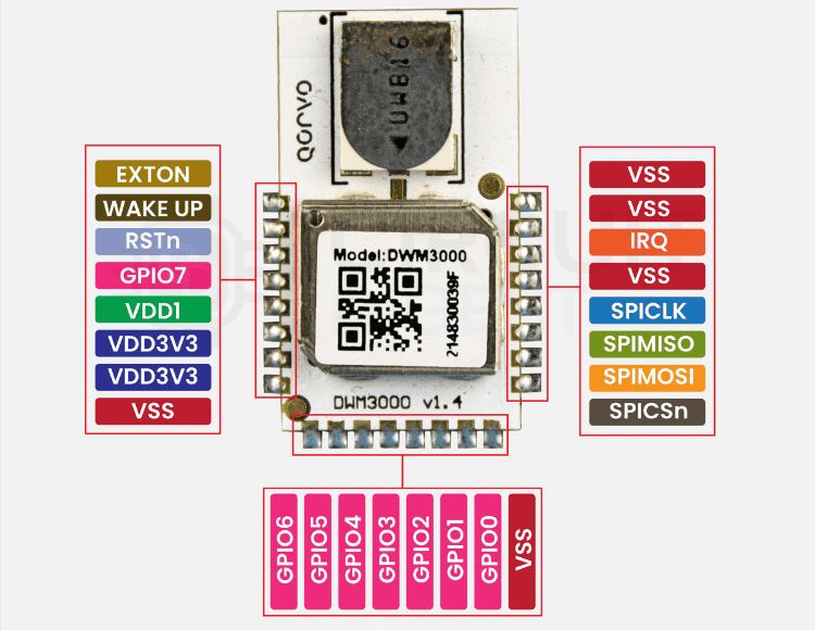
The Qorvo DWM3000 is a compact, fully integrated Ultra-Wideband (UWB) transceiver module designed for high-accuracy location and ranging applications in a UWB positioning system. Built around Qorvo’s DW3110 IC, it complies with the IEEE 802.15.4z standard and is fully interoperable with the FiRa Consortium PHY/MAC specifications, meaning it can work with other UWB devices in the ecosystem. The Qorvo DWM3000 is a compact, fully integrated Ultra-Wideband (UWB) transceiver module designed for high-accuracy location and ranging applications in a UWB positioning system.
Unlike bare ICs, the DWM3000 comes as a ready-to-use RF module, which means you don’t have to be an RF engineer to get it working in your UWB positioning system. It already includes a high-performance ceramic UWB antenna with omnidirectional characteristics. It has all RF passives, a 38.4 MHz crystal oscillator, and a complete power management system onboard.
This “plug-and-play” design is particularly appealing for developers who want cutting-edge location technology without spending months on RF design.
How Does a UWB Indoor Positioning System Using ESP32 Work? (Step-by-Step)
Building an indoor positioning system using UWB technology involves these key steps:
1. Anchor placement: Place 3 or more UWB anchors at known locations (coordinates) in your environment for best coverage in a UWB Real-Time Location System (RTLS). The anchor placement, tag firmware, and trilateration logic all aim to deliver reliable ESP32 indoor positioning, down to centimetre-level accuracy inside complex indoor spaces.
2. Tag initiation: The mobile UWB positioning device (tag) initiates the anchors to range.
3. Two-Way Ranging: Tags and anchors use time-of-flight with one-nanosecond precision, sending and receiving precise UWB pulses.
4. Distance calculations: Using Double-Sided TWR on the tags calculates the distance between the tag and the anchors for UWB location tracking
5. Trilateration: A Python script collects the distances from 3 or more anchors and computes the exact (x,y) coordinates
6. Real-time visualisation: The positional data from the tag is streamed over Wi-Fi to present the tracking live on the floor plan for UWB asset tracking.
DWM3000 Capabilities for Indoor Positioning Systems Using ESP32
Why UWB Technology Excels in Indoor Positioning System Applications
UWB’s key advantage is its ability to measure time-of-flight with extreme precision. Since the DWM3000 is built for 802.15.4z, it transmits very short pulses (on the order of nanoseconds) across a wide frequency range. This makes the UWB positioning system resistant to multipath interference, a common problem indoors where walls, ceilings, and metal surfaces cause reflections.
For indoor positioning, multipath can make Wi-Fi or Bluetooth wildly inaccurate, but UWB, especially the DWM3000, can filter out those reflections and focus on the direct path signal, giving you centimetre-level accuracy even in cluttered rooms.
The UWB positioning system is therefore resilient to multipath interference that is often encountered indoors from reflection off walls, ceilings, and metal surfaces.
In an indoor UWB localisation system, a signal that takes a longer path via multipath can cause Wi-Fi or Bluetooth to be extremely inaccurate, while UWB will be able to discard unwanted reflections and focus solely on a direct path signal, particularly the DWM3000 UWB positioning module. UWB location tracking systems are great for enclosed spaces where reflection from metal shelving is common, and tracking assets is important in an industrial setting is essential. Because traditional Bluetooth or WiFi systems struggle with reflections and multipath indoors, this approach uses UWB for precision — enabling a complete ESP32 indoor positioning solution rather than just coarse zone tracking.
Other Qorvo UWB Modules for Indoor Positioning Systems Using ESP32
Qorvo offers several UWB modules with similar form factors but different chipsets, frequency capabilities, and standards compliance, suitable for various UWB positioning system implementations. Here’s a quick comparison:
What We Used for This UWB Indoor Positioning System Using ESP32 Project
In my Indoor UWB location tracking system, I didn’t use every feature the DWM3000 offers; I focused on the capabilities that were essential for a real-time 2D indoor tracking system, to make the UWB indoor positioning system using ESP32:
- Double-Sided Two-Way Ranging (DS-TWR) Mode to accurately measure tag to anchor distances
- Channel 5 (6.5 GHz) operation, providing consistent performance for my UWB indoor positioning system using ESP32. Supports UWB Channel 5 (6.5 GHz) and Channel 9 (8 GHz), both suitable for global use in UWB RTLS applications
- SPI communications to the ESP32 host microcontroller
- Standard antenna delay calibration, to further optimise accuracy for UWB indoor localisation
- High data rate (6.8 Mbps) to measure and complete faster measurement cycles for real-time UWB location tracking
In addition, beyond UWB asset tracking, the DWM3000 also supports options such as TDoA, low-power tag modes, and multi-channel operation, should I wish to later scale the system for multi-tag tracking, or operate in larger open spaces as a comprehensive UWB RTLS deployment.
Along with UWB asset tracking, features like TDoA, low-power tag modes, and multi-channel operation are also available if I want to scale the system later for multi-tag tracking or larger spaces.
Components Required for Building Your UWB Indoor Positioning System Using ESP32
To build this UWB indoor positioning system using ESP32, you’ll need the following hardware:
Hardware Setup and Pin Connections for UWB Indoor Localisation
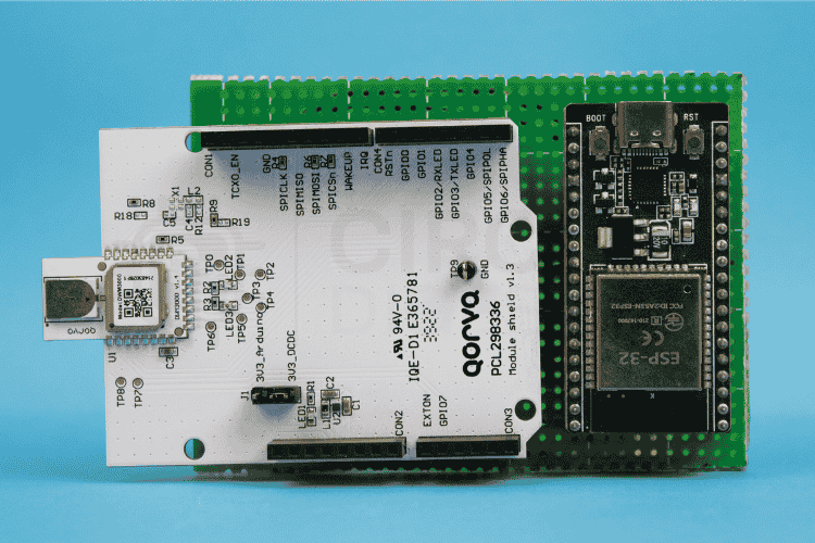
To make the DWM3000 modules work as a Tag and Anchor roles in this indoor UWB positioning system project, we connect them to ESP32 boards using SPI. To make the DWM3000 modules work as a Tag and Anchor roles in this indoor UWB positioning system project, we connect them to ESP32 boards using SPI. Each ESP32-DWM3000 pair will have the same wiring, but each Anchor will be given a unique ANCHOR_ID in code. The Tag’s ESP32 is programmed with the tag firmware, while Anchors run the anchor firmware.
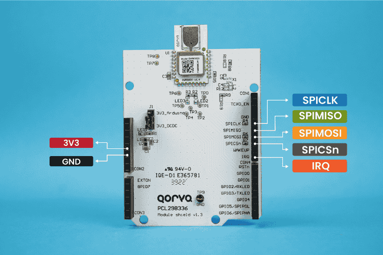
ESP32 to DWM3000 Pin Mapping for UWB Positioning Module:

Warning!: The DWM3000 module operates only at 3.3V. Supplying a higher voltage can damage it. Ensure the power source is clean and has minimal noise for stable operation.
Anchor Arrangement in Room for UWB RTLS Setup
We recommend placing three anchors in fixed, known positions for trilateration in your UWB location tracking system:
Note!: These coordinates should match the ANCHOR_POSITIONS array in your Python floorview script.
How the Tag Talks to the Anchors in the UWB Indoor Positioning System Using ESP32
In our UWB indoor localisation setup, the tag is the initiator and the anchors are the responders. Each anchor’s position is fixed and known in advance. The tag’s job is to measure how far it is from each anchor, and it does that using a precise exchange of UWB messages. This process is called Two-Way Ranging (TWR), and for the highest accuracy, we use a version called Double-Sided TWR (DS-TWR) in our UWB positioning system.
Capturing the Exact Moments in Time for UWB Location Tracking
Every time the DWM3000 transmits or receives a UWB frame, it records a hardware timestamp, an ultra-precise counter value straight from the radio’s internal clock. These timestamps are accurate to fractions of a nanosecond, and they are the secret to UWB’s centimetre-level precision in UWB asset tracking. The ESP32 never relies on its own CPU clock for this; it simply reads the radio’s timestamps using API functions like readtxtimestamp() and readrxtimestamp().
The Three-Message Exchange in UWB Indoor Positioning System Using ESP32
Here's what happens during a ranging session with one anchor in your UWB RTLS setup:
- Poll: The tag sends a “Poll” message at time T1 and records the transmit timestamp.
- Response: The anchor receives the Poll at T2, waits for a known reply delay, then transmits a “Response” at T3. The anchor records both T2 and T3
- Final: The tag receives the Response at T4, then sends a “Final” message that includes its own recorded timestamps so the anchor can calculate the Time of Flight (ToF).
This three-step exchange allows both sides to share timing information and removes the need for synchronised clocks in the UWB indoor localisation process.
Asymmetric Double Sided Two Way Ranging algorithm Math
In Asymmetric Double Sided Two Way Ranging there is no waiting time When the Anchor receives a message, it replies immediately, Because the code processing speed varies, the Tag's reply time (Treply1) will not match the Anchor's reply time (Treply2). The system relies on measuring the clock drift to mathematically correct the errors caused by these unequal reply times. The calculation uses four time intervals, all measured in the DWM3000’s hardware tick units:
- Tround1 = T4 - T1 (tag’s round trip for the first exchange)
- Treply1 = T3 - T2 (anchor’s reply delay after receiving poll)
- Tround2 = T6 - T3 (anchor’s round trip for the second exchange)
- Treply2 = T5 - T4 (tag’s reply delay after receiving response)
These four measured numbers are the input to the TWR algebra used in the UWB positioning system..
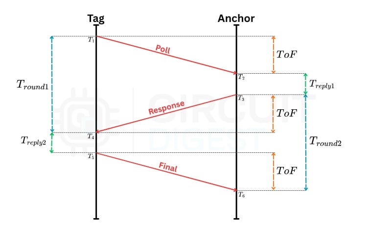
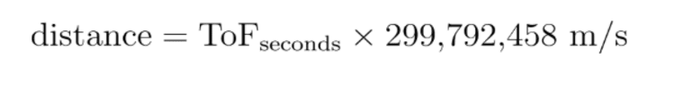
The ToF is then computed as:

Once we have the ToF in ticks, we convert it to seconds using the DWM3000’s tick period, and then to distance using the speed of light for accurate UWB indoor localisation:
What we used in our Project
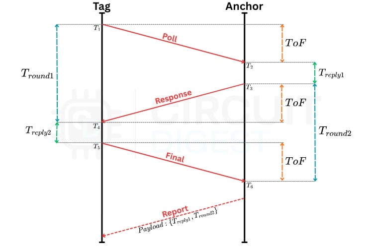
In our code implementation we added additional packet transmission from anchor to tag after final transmission to send Treply1 and Tround2 to tag side because in our project we used tag to compute the distance between each anchor for that we need those time intervals from anchor point.
Antenna Delay and Calibration for UWB Indoor Positioning System Using ESP32
The DWM3000’s internal signal path and antenna introduce a small, fixed delay in both transmit and receive. If we don’t compensate for it, our distance will always be off by a few centimetres in the UWB RTLS system. The UWB positioning module lets us set TX and RX antenna delays in device ticks after calibration. This is done once for each module and then stored in the firmware.
Making the Measurements Reliable
UWB is highly resistant to multipath, but poor geometry or obstructions can still cause errors. To mitigate this in our indoor UWB positioning system project, the firmware applies simple averaging to filter out noisy measurements, while RSSI values are monitored to detect potential non-line-of-sight (NLOS) conditions that could affect UWB location tracking accuracy.
From JSON Data to Real-Time Position in UWB Asset Tracking
Once the tag has calculated its distances to all three anchors, the next step is to send that information to the PC so it can work out the tag’s coordinates and display them in real time. For this, we use JSON, a lightweight text-based format that’s easy for both the ESP32 and Python to handle. For this UWB indoor positioning system using ESP32, we use JSON, a lightweight text-based format that's easy for both the ESP32 and Python to handle.
The JSON Format for UWB RTLS Data
Here's an example of what the tag sends after each ranging cycle in the UWB location tracking system:
{
       "tag_id": 10,
       "anchors": {
           "A1": {
               "distance": 116.82,
               "raw": 116.82,
               "rssi": -62.23,
               "fp_rssi": -63.10,
               "round_time": 66071380,
               "reply_time": 81007788,
               "clock_offset": -0.000004
           },
           "A2": {
               "distance": 112.60,
               "raw": 115.42,
               "rssi": -68.32,
               "fp_rssi": -73.36,
               "round_time": 68508406,
               "reply_time": 79276298,
               "clock_offset": -0.000001
           },
           "A3": {
               "distance": 123.86,
               "raw": 124.33,
               "rssi": -68.28,
               "fp_rssi": -69.81,
               "round_time": 68377096,
               "reply_time": 79564280,
               "clock_offset": -0.000001
           }
       }
   }
Each anchor has a label (A1, A2, A3), and inside each entry we store:
- tag_id: A numeric ID for the tag, useful if you’re tracking multiple tags at once in your UWB RTLS deployment.
Inside each anchor entry (A1, A2, A3): - distance: The final, calibrated distance in centimetres after applying antenna delay compensation and any filtering for UWB indoor localisation. This is the value used for trilateration.
- raw: The raw uncalibrated distance in centimetres, directly from the DS-TWR math before applying corrections.
- rssi: The estimated signal strength of the received packet, in dBm.
- fp_rssi: The signal strength measured at the first path, which helps determine if the direct path is weaker than reflections (useful for NLOS detection, UWB asset tracking).
- round_time: The total round-trip time of the message exchange, in device clock ticks.
- reply_time: How long the responder (anchor) took to reply, in device ticks.
- clock_offset: The fractional clock drift between the tag and the anchor, useful for diagnostics and improving ranging accuracy.
The ESP32 sends this JSON string over Wi-Fi to the PC, where our Python script is ready to process it for real-time UWB location tracking visualisation.
Receiving and Parsing in Python for UWB Indoor Positioning System Using ESP32
On the PC, the Python script:
- Listens for incoming TCP data from the tag in the UWB positioning system.
- Reads the JSON string and converts it into a Python dictionary with json.loads().
- Extracts the distances and RSSI values for each anchor for UWB indoor localisation processing.
The script already knows each anchor's fixed coordinates in the room for the UWB RTLS setup, for example:
{
       "tag_id": 10,
       "anchors": {
           "A1": {
               "distance": 116.82,
               "raw": 116.82,
               "rssi": -62.23,
               "fp_rssi": -63.10,
               "round_time": 66071380,
               "reply_time": 81007788,
               "clock_offset": -0.000004
           },
           "A2": {
               "distance": 112.60,
               "raw": 115.42,
               "rssi": -68.32,
               "fp_rssi": -73.36,
               "round_time": 68508406,
               "reply_time": 79276298,
               "clock_offset": -0.000001
           },
           "A3": {
               "distance": 123.86,
               "raw": 124.33,
               "rssi": -68.28,
               "fp_rssi": -69.81,
               "round_time": 68377096,
               "reply_time": 79564280,
               "clock_offset": -0.000001
           }
       }
   }
The script already knows each anchor’s fixed coordinates in the room, for example:
anchors = {
   "A1": (15.0, 5.0),
   "A2": (300.0, 5.0),
   "A3": (165.0, 625.0)
}
The Mathematics of Trilateration in a UWB Indoor Positioning System Using ESP32
If you plot the anchors on a graph and draw a circle around each one with a radius equal to the measured distance, the tag should be located where the circles intersect. This is the fundamental principle behind UWB indoor localisation.
Mathematically, each anchor gives you one equation in the UWB positioning system:
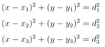
Where (x1,y1), (x2,y2), (x3, y3) are anchor positions and d1, d2, d3 are measured distances from the JSON packet in your UWB location tracking system.
Handling Real-World Imperfections in UWB RTLS
In practice, noise and small ranging errors mean the likelihood of the circles intersecting at the same point in a real UWB indoor positioning system is remote. This is the reason the script uses least squares optimisation for accurate UWB asset tracking.
SciPy has a least_squares() function that performs the optimisation automatically to identify the best fit position for UWB indoor localisation.
In reality, noise and small ranging errors mean these circles rarely intersect at exactly one point. That’s why the script uses least squares optimisation:
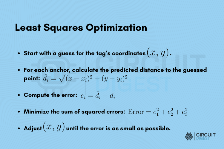
This is done using SciPy’s least_squares() function, which handles the optimisation automatically.
Real-Time Plotting for UWB Location Tracking
Once the best-fit position (x,y) is found, the script:
- Plots the anchors as fixed points.
- Shows the tag’s current location as a moving dot.
- Displays each anchor’s RSSI above it for live signal strength monitoring in the UWB RTLS system.
The plot updates continuously as new JSON packets arrive, giving a smooth, real-time view of the tag’s movement around the space for effective UWB asset tracking.
ESP32 Tag Firmware Setup for Indoor Positioning System
#include <SPI.h>
#include <WiFi.h>
#include <WiFiClient.h>
// WiFi Configuration
const char *ssid = "Semicon Media";
const char *password = "xxxxxxxxx";
const char *host = "192.168.xx.xx"; // Your PC's IP address
const int port = 7007;             // Choose a port number
WiFiClient client;
bool wifiConnected = false;
Set the base anchor ID number, making it easy to add more anchors later without reworking the whole codebase for your UWB RTLS deployment.
The firmware begins by including the core libraries, SPI.h for high-speed communication with the DWM3000 UWB positioning module, and WiFi.h/WiFiClient.h for network connectivity. The SSID, password, and server details are hardcoded here so the ESP32 can immediately connect to your local network and open a TCP connection to the PC running the Python visualisation script UWB indoor localisation.
System Initialisation and UWB Tag Setup
// SPI Setup
#define RST_PIN 27
#define CHIP_SELECT_PIN 4
// Scalable Anchor Configuration
#define NUM_ANCHORS 3 // Change this to scale the system
#define TAG_ID 10
#define FIRST_ANCHOR_ID 1 // Starting ID for anchors (1, 2, 3, ...)
The SPI control pins are defined for the UWB indoor positioning system using ESP32. RST_PIN allows the ESP32 to reset the DWM3000, and CHIP_SELECT_PIN controls which SPI device is active. The anchor configuration block specifies the total number of anchors, assigns a unique tag ID, and sets the base anchor ID number, making it easy to add more anchors later without reworking the whole codebase for your UWB RTLS deployment.
// Ranging Configuration
#define FILTER_SIZE 50 // For median filter
#define MIN_DISTANCE 0
#define MAX_DISTANCE 10000.0
The ranging parameters control how many distance samples are stored for filtering (FILTER_SIZE), and what distance values are considered valid (MIN_DISTANCE and MAX_DISTANCE). These checks prevent impossible values from contaminating the position calculation.
// UWB Configuration
#define LEN_RX_CAL_CONF 4
#define LEN_TX_FCTRL_CONF 6
#define LEN_AON_DIG_CFG_CONF 3
#define PMSC_STATE_IDLE 0x3
#define FCS_LEN 2
#define STDRD_SYS_CONFIG 0x188
#define DTUNE0_CONFIG 0x0F
#define SYS_STATUS_FRAME_RX_SUCC 0x2000
#define SYS_STATUS_RX_ERR 0x4279000
#define SYS_STATUS_FRAME_TX_SUCC 0x80
#define PREAMBLE_32 4
#define PREAMBLE_64 8
#define PREAMBLE_128 5
#define PREAMBLE_256 9
#define PREAMBLE_512 11
#define PREAMBLE_1024 2
#define PREAMBLE_2048 10
#define PREAMBLE_4096 3
#define PREAMBLE_1536 6
#define CHANNEL_5 0x0
#define CHANNEL_9 0x1
#define PAC4 0x03
#define PAC8 0x00
#define PAC16 0x01
#define PAC32 0x02
#define DATARATE_6_8MB 0x1
#define DATARATE_850KB 0x0
#define PHR_MODE_STANDARD 0x0
#define PHR_MODE_LONG 0x1
#define PHR_RATE_6_8MB 0x1
#define PHR_RATE_850KB 0x0
#define SPIRDY_MASK 0x80
#define RCINIT_MASK 0x100
#define BIAS_CTRL_BIAS_MASK 0x1F
#define GEN_CFG_AES_LOW_REG 0x00
#define GEN_CFG_AES_HIGH_REG 0x01
#define STS_CFG_REG 0x2
#define RX_TUNE_REG 0x3
#define EXT_SYNC_REG 0x4
#define GPIO_CTRL_REG 0x5
#define DRX_REG 0x6
#define RF_CONF_REG 0x7
#define RF_CAL_REG 0x8
#define FS_CTRL_REG 0x9
#define AON_REG 0xA
#define OTP_IF_REG 0xB
#define CIA_REG1 0xC
#define CIA_REG2 0xD
#define CIA_REG3 0xE
#define DIG_DIAG_REG 0xF
#define PMSC_REG 0x11
#define RX_BUFFER_0_REG 0x12
#define RX_BUFFER_1_REG 0x13
#define TX_BUFFER_REG 0x14
#define ACC_MEM_REG 0x15
#define SCRATCH_RAM_REG 0x16
#define AES_RAM_REG 0x17
#define SET_1_2_REG 0x18
#define INDIRECT_PTR_A_REG 0x1D
#define INDIRECT_PTR_B_REG 0x1E
#define IN_PTR_CFG_REG 0x1F
#define TRANSMIT_DELAY 0x3B9ACA00
#define TRANSMIT_DIFF 0x1FF
#define NS_UNIT 4.0064102564102564    // ns
#define PS_UNIT 15.6500400641025641   // ps
#define SPEED_OF_LIGHT 0.029979245800 // in centimetres per picosecond
#define CLOCK_OFFSET_CHAN_5_CONSTANT -0.5731e-3f
#define CLOCK_OFFSET_CHAN_9_CONSTANT -0.1252e-3f
#define NO_OFFSET 0x0
#define DEBUG_OUTPUT 0
static int ANTENNA_DELAY = 16350;
This large block of definitions maps directly to DWM3000 configuration registers, constants, and tuning values. It includes UWB channel numbers, preamble lengths, PAC sizes, data rates, PHR modes, register addresses, and clock offset compensation constants for different channels. The ANTENNA_DELAY setting fine-tunes the signal travel time through the RF front-end, improving ranging accuracy to the centimetre level.
// Initial Radio Configuration
int config[] = {
   CHANNEL_5,         // Channel
   PREAMBLE_128,      // Preamble Length
   9,                 // Preamble Code (Same for RX and TX!)
   PAC8,              // PAC
   DATARATE_6_8MB,    // Datarate
   PHR_MODE_STANDARD, // PHR Mode
   PHR_RATE_850KB     // PHR Rate
};
The config[] array gathers the most important initial radio settings in one place. This project uses Channel 5, a 128-symbol preamble with code 9, PAC length 8, the fastest 6.8 Mb/s data rate, and standard PHR mode. These settings strike a balance between performance and reliability for indoor ranging.
// Anchor data structure
struct AnchorData
{
   int anchor_id; // Anchor ID
   // Timing measurements
   int t_roundA = 0;
   int t_replyA = 0;
   long long rx = 0;
   long long tx = 0;
   int clock_offset = 0;
   // Distance measurements
   float distance = 0;
   float distance_history[FILTER_SIZE] = {0};
   int history_index = 0;
   float filtered_distance = 0;
   // Signal quality metrics
   float signal_strength = 0;    // RSSI in dBm
   float fp_signal_strength = 0; // First Path RSSI in dBm
};
The AnchorData struct packages all relevant information for a single anchor: timing measurements from the DS-TWR exchange, raw and filtered distances, a rolling history for median filtering, and signal quality metrics (RSSI and first path RSSI). This keeps all per-anchor data organised and easy to access during ranging and JSON construction.
// Dynamic array of anchor data
AnchorData anchors[NUM_ANCHORS];
// Helper functions for anchor management
void initializeAnchors()
{
  for (int i = 0; i < NUM_ANCHORS; i++)
  {
      anchors[i].anchor_id = FIRST_ANCHOR_ID + i;
      // Initialize all other fields to zero (default constructor handles this)
  }
}
AnchorData *getCurrentAnchor()
{
  return &anchors[current_anchor_index];
}
int getCurrentAnchorId()
{
  return anchors[current_anchor_index].anchor_id;
}
void switchToNextAnchor()
{
  current_anchor_index = (current_anchor_index + 1) % NUM_ANCHORS;
}
bool allAnchorsHaveValidData()
{
  for (int i = 0; i < NUM_ANCHORS; i++)
  {
      if (anchors[i].filtered_distance <= 0)
      {
          return false;
      }
  }
  return true;
}
Finally, a set of helper functions manages the anchors in memory. initializeAnchors() assigns IDs, getCurrentAnchor() and getCurrentAnchorId() provide quick access to the active anchor, switchToNextAnchor() rotates through anchors in sequence, and allAnchorsHaveValidData() confirms that every anchor has a valid reading before attempting a position calculation.
Inside the DWM3000 Driver Class
class DWM3000Class
{
public:
   // Chip Setup
   static void spiSelect(uint8_t cs);
   static void begin();
   static void init();
   static void writeSysConfig();
   static void configureAsTX();
   static void setupGPIO();
   // Double-Sided Ranging
   static void ds_sendFrame(int stage);
   static void ds_sendRTInfo(int t_roundB, int t_replyB);
   static int ds_processRTInfo(int t_roundA, int t_replyA, int t_roundB, int t_replyB, int clock_offset);
   static int ds_getStage();
   static bool ds_isErrorFrame();
   static void ds_sendErrorFrame();
   // Radio Settings
   static void setChannel(uint8_t data);
   static void setPreambleLength(uint8_t data);
   static void setPreambleCode(uint8_t data);
   static void setPACSize(uint8_t data);
   static void setDatarate(uint8_t data);
   static void setPHRMode(uint8_t data);
   static void setPHRRate(uint8_t data);
   // Protocol Settings
   static void setMode(int mode);
   static void setTXFrame(unsigned long long frame_data);
   static void setFrameLength(int frame_len);
   static void setTXAntennaDelay(int delay);
   static void setSenderID(int senderID);
   static void setDestinationID(int destID);
   // Status Checks
   static int receivedFrameSucc();
   static int sentFrameSucc();
   static int getSenderID();
   static int getDestinationID();
   static bool checkForIDLE();
   static bool checkSPI();
   // Radio Analytics
   static double getSignalStrength();
   static double getFirstPathSignalStrength();
   static int getTXAntennaDelay();
   static long double getClockOffset();
   static long double getClockOffset(int32_t ext_clock_offset);
   static int getRawClockOffset();
   static float getTempInC();
   static unsigned long long readRXTimestamp();
   static unsigned long long readTXTimestamp();
   // Chip Interaction
   static uint32_t write(int base, int sub, uint32_t data, int data_len);
   static uint32_t write(int base, int sub, uint32_t data);
   static uint32_t read(int base, int sub);
   static uint8_t read8bit(int base, int sub);
   static uint32_t readOTP(uint8_t addr);
   // Delayed Sending Settings
   static void writeTXDelay(uint32_t delay);
   static void prepareDelayedTX();
   // Radio Stage Settings / Transfer and Receive Modes
   static void delayedTXThenRX();
   static void delayedTX();
   static void standardTX();
   static void standardRX();
   static void TXInstantRX();
   // DWM3000 Firmware Interaction
   static void softReset();
   static void hardReset();
   static void clearSystemStatus();
   // Hardware Status Information
   static void pullLEDHigh(int led);
   static void pullLEDLow(int led);
   // Calculation and Conversion
   static double convertToCM(int DWM3000_ps_units);
   static void calculateTXRXdiff();
   // Printing
   static void printRoundTripInformation();
   static void printDouble(double val, unsigned int precision, bool linebreak);
private:
   // Single Bit Settings
   static void setBit(int reg_addr, int sub_addr, int shift, bool b);
   static void setBitLow(int reg_addr, int sub_addr, int shift);
   static void setBitHigh(int reg_addr, int sub_addr, int shift);
   // Fast Commands
   static void writeFastCommand(int cmd);
   // SPI Interaction
   static uint32_t readOrWriteFullAddress(uint32_t base, uint32_t sub, uint32_t data, uint32_t data_len, uint32_t readWriteBit);
   static uint32_t sendBytes(int b[], int lenB, int recLen);
   // Soft Reset Helper Method
   static void clearAONConfig();
   // Other Helper Methods
   static unsigned int countBits(unsigned int number);
   static int checkForDevID();
};
DWM3000Class DWM3000;
This section defines the DWM3000Class, a custom driver wrapper that handles all direct communication with the DWM3000 UWB transceiver. It abstracts away the complex register operations, timing control, and ranging protocol steps into a clean, reusable API for the rest of the firmware.
The class is divided into functional groups:
- Chip Setup methods handle SPI selection, initialisation, and GPIO configuration.
- Double-Sided Ranging methods implement the DS-TWR protocol, from sending and receiving frames to calculating the final distance.
- Radio & Protocol Settings allow quick switching of channel, preamble, data rate, and addressing.
- Status & Analytics functions read signal strength, timestamps, and clock offset, essential for both ranging accuracy and debugging.
- Hardware Interaction methods perform resets, LED control, and delayed transmission scheduling.
- Low-Level Access routines read and write directly to the DWM3000’s registers, enabling advanced custom tuning when needed.
By wrapping all these functions in a dedicated class, the rest of the tag firmware can perform complex UWB ranging and diagnostics with just a few high-level calls, keeping the main code clean and readable while still giving full control over the hardware.
Wi-Fi Communication and JSON Data Handling
// Send ranging data to host
void sendDataOverWiFi() { ... }
// Validate a measurement
bool isValidDistance(float distance) { ... }

// Apply median filtering
float calculateMedian(float arr[], int size) { ... }

// Update anchor’s filtered distance
void updateFilteredDistance(AnchorData &data) { ... }

// Print debug info for one anchor
void printDebugInfo(int anchor, long long rx, long long tx, int t_round, int t_reply, int clock_offset) { ... }

// Print all anchors’ filtered distances
void printAllDistances() { ... }
This section of the firmware handles all network connectivity and data formatting. The tag first connects to Wi-Fi using connectToWiFi() and maintains the connection. Each ranging cycle, sendDataOverWiFi() builds a structured JSON payload containing every anchor’s filtered distance, raw measurement, RSSI, first-path RSSI, timing values, and clock offset, then sends it over TCP to the Python host script. To ensure stability, isValidDistance() and calculateMedian() filter noisy readings before transmission. updateFilteredDistance() maintains a rolling history of each anchor’s measurements, while printDebugInfo() and printAllDistances() provide quick on-device monitoring for troubleshooting. Together, these functions form the bridge between low-level UWB measurements and real-time position plotting on your computer.
System Initialisation and UWB Tag Setup
void setup()
{
   Serial.begin(115200);
// Initialize anchor array
   initializeAnchors();

   Serial.print("Initialized ");
   Serial.print(NUM_ANCHORS);
   Serial.println(" anchors:");
   for (int i = 0; i < NUM_ANCHORS; i++) {
       Serial.print("  Anchor ");
       Serial.print(i);
       Serial.print(" - ID: ");
       Serial.println(anchors[i].anchor_id);
   }
   // Connect to WiFi first
   connectToWiFi();
   // Initialize UWB
   DWM3000.begin();
   DWM3000.hardReset();
   delay(200);
   if (!DWM3000.checkSPI())
   {
       Serial.println("[ERROR] Could not establish SPI Connection to DWM3000!");
       while (1)
           ;
   }
   while (!DWM3000.checkForIDLE())
   {
       Serial.println("[ERROR] IDLE1 FAILED\r");
       delay(1000);
   }
   DWM3000.softReset();
   delay(200);
   if (!DWM3000.checkForIDLE())
   {
       Serial.println("[ERROR] IDLE2 FAILED\r");
       while (1)
           ;
   }
   DWM3000.init();
   DWM3000.setupGPIO();
   DWM3000.setTXAntennaDelay(16350);
   DWM3000.setSenderID(TAG_ID);
   Serial.println("> TAG - Three Anchor Ranging System <");
   Serial.println("> With WiFi Communication <\n");
   Serial.println("[INFO] Setup is finished.");
   Serial.print("Antenna delay set to: ");
   Serial.println(DWM3000.getTXAntennaDelay());
   DWM3000.configureAsTX();
   DWM3000.clearSystemStatus();
}
The setup() function runs once at startup and prepares the entire UWB indoor positioning system using ESP32. It begins by opening a serial connection for debugging and initialising the anchor list with unique IDs. Next, it connects the ESP32 to the Wi-Fi network so data streaming is ready from the start for UWB location tracking. The DWM3000 UWB transceiver is then powered up, hard-reset, and checked for proper SPI communication. The firmware ensures the chip is in an IDLE state before applying a soft reset and proceeding with initialisation. GPIOs are configured, the antenna delay is set for accurate timing, and the tag’s unique ID is assigned. Finally, the DWM3000 is placed in transmit mode and its system status registers are cleared, leaving the tag ready to begin the ranging loop.
Main Ranging Loop for UWB Location Tracking
void loop()
{
   AnchorData* currentAnchor = getCurrentAnchor();
   int currentAnchorId = getCurrentAnchorId();
   switch (curr_stage)
   {
   case 0: // Start ranging with current target
       // Reset timing measurements for current anchor
       currentAnchor->t_roundA = 0;
       currentAnchor->t_replyA = 0;

       DWM3000.setDestinationID(currentAnchorId);
       DWM3000.ds_sendFrame(1);
       currentAnchor->tx = DWM3000.readTXTimestamp();
       curr_stage = 1;
       break;
   case 1: // Await first response
       if (rx_status = DWM3000.receivedFrameSucc())
       {
           DWM3000.clearSystemStatus();
           if (rx_status == 1)
           {
               if (DWM3000.ds_isErrorFrame())
               {
                   Serial.print("[WARNING] Error frame from Anchor ");
                   Serial.print(currentAnchorId);
                   Serial.print("! Signal strength: ");
                   Serial.print(DWM3000.getSignalStrength());
                   Serial.println(" dBm");
                   curr_stage = 0;
               }
               else if (DWM3000.ds_getStage() != 2)
               {
                   Serial.print("[WARNING] Unexpected stage from Anchor ");
                   Serial.print(currentAnchorId);
                   Serial.print(": ");
                   Serial.println(DWM3000.ds_getStage());
                   DWM3000.ds_sendErrorFrame();
                   curr_stage = 0;
               }
               else
               {
                   curr_stage = 2;
               }
           }
           else
           {
               Serial.print("[ERROR] Receiver Error from Anchor ");
               Serial.println(currentAnchorId);
               DWM3000.clearSystemStatus();
           }
       }
       break;
   case 2: // Response received. Send second ranging
       currentAnchor->rx = DWM3000.readRXTimestamp();
       DWM3000.ds_sendFrame(3);

       currentAnchor->t_roundA = currentAnchor->rx - currentAnchor->tx;
       currentAnchor->tx = DWM3000.readTXTimestamp();
       currentAnchor->t_replyA = currentAnchor->tx - currentAnchor->rx;

       curr_stage = 3;
       break;
   case 3: // Await second response
       if (rx_status = DWM3000.receivedFrameSucc())
       {
           DWM3000.clearSystemStatus();
           if (rx_status == 1)
           {
               if (DWM3000.ds_isErrorFrame())
               {
                   Serial.print("[WARNING] Error frame from Anchor ");
                   Serial.println(currentAnchorId);
                   curr_stage = 0;
               }
               else
               {
                   currentAnchor->clock_offset = DWM3000.getRawClockOffset();
                   curr_stage = 4;
               }
           }
           else
           {
               Serial.print("[ERROR] Receiver Error from Anchor ");
               Serial.println(currentAnchorId);
               DWM3000.clearSystemStatus();
           }
       }
       break;
   case 4: // Response received. Calculating results
       {
           int ranging_time = DWM3000.ds_processRTInfo(
               currentAnchor->t_roundA,
               currentAnchor->t_replyA,
               DWM3000.read(0x12, 0x04),
               DWM3000.read(0x12, 0x08),
               currentAnchor->clock_offset);

           currentAnchor->distance = DWM3000.convertToCM(ranging_time);
           currentAnchor->signal_strength = DWM3000.getSignalStrength();
           currentAnchor->fp_signal_strength = DWM3000.getFirstPathSignalStrength();
           updateFilteredDistance(*currentAnchor);
       }
       // Print current distances
       printAllDistances();
       // Send data over WiFi if all anchors have valid data
       if (allAnchorsHaveValidData())
       {
           sendDataOverWiFi();
       }
       // Switch to next anchor
       switchToNextAnchor();
       curr_stage = 0;
       break;
   default:
       Serial.print("Entered stage (");
       Serial.print(curr_stage);
       Serial.println("). Reverting back to stage 0");
       curr_stage = 0;
       break;
   }
}
The loop() function drives the double-sided two-way ranging (DS-TWR) process with each anchor in turn UWB indoor positioning system using ESP32. It operates as a small state machine (curr_stage) that moves step-by-step through the ranging exchange to enable precise UWB indoor localisation. Stage 0 sends the first frame to the current anchor and records the transmit timestamp. Stage 1 waits for a valid reply, checking for error frames or unexpected stages. Stage 2 sends the second frame and logs timing data (t_roundA and t_replyA). Stage 3 waits for the anchor’s final response, reading its clock offset for drift compensation. Stage 4 processes all timing measurements using ds_processRTInfo(), converts the result to centimetres, stores signal strength metrics, and updates the median-filtered distance. If all anchors have valid distances, the tag sends a complete JSON update to the host via Wi-Fi. The loop then switches to the next anchor and repeats. This continuous cycle keeps the host updated with fresh distance measurements for real-time positioning. The loop continuously cycles through all anchors in your UWB RTLS setup, maintaining real-time distance measurements for accurate UWB asset tracking and position calculation.
Breaking Down the Anchor Firmware Setup
#include <Arduino.h>
#include <SPI.h>
// SPI Setup
#define RST_PIN 27
#define CHIP_SELECT_PIN 4
// Set to 1 for Anchor 1, 2 for Anchor 2
#define ANCHOR_ID 1
#define RESPONSE_TIMEOUT_MS 10  // Maximum time to wait for a response
unsigned long last_ranging_time = 0;
#define MAX_RETRIES 3
int retry_count = 0;
static int rx_status;
static int tx_status;
/*
  valid stages:
  0 - default stage; await ranging
  1 - ranging received; sending response
  2 - response sent; await second response
  3 - second response received; sending information frame
  4 - information frame sent
*/
static int curr_stage = 0;
static int t_roundB = 0;
static int t_replyB = 0;
static long long rx = 0;
static long long tx = 0;
#define LEN_RX_CAL_CONF 4
#define LEN_TX_FCTRL_CONF 6
#define LEN_AON_DIG_CFG_CONF 3
#define PMSC_STATE_IDLE 0x3
...
#define TRANSMIT_DIFF 0x1FF
#define NS_UNIT 4.0064102564102564   // ns
#define PS_UNIT 15.6500400641025641  // ps
#define SPEED_OF_LIGHT 0.029979245800  // in centimetres per picosecond
#define CLOCK_OFFSET_CHAN_5_CONSTANT -0.5731e-3f
#define CLOCK_OFFSET_CHAN_9_CONSTANT -0.1252e-3f
// Offsets
#define NO_OFFSET 0x0
#define DEBUG_OUTPUT 0  // Turn to 1 to get all reads, writes, etc. as info in the console
static int ANTENNA_DELAY = 16350;
int led_status = 0;
int destination = 0x0;  // Default Values for Destination and Sender IDs
int sender = 0x0;
On the anchor side, the firmware begins by setting up the hardware interface for the DWM3000, including the SPI pins (RST_PIN, CHIP_SELECT_PIN) and the unique ANCHOR_ID that distinguishes each anchor in the network. It also defines timing parameters like RESPONSE_TIMEOUT_MS for how long the anchor waits for tag communication, and constants for maximum retries.
The rest of the definitions configure UWB communication parameters: preamble lengths, channels, PAC sizes, data rates, and various register addresses/masks used internally by the DWM3000 chip. These constants ensure the anchor is tuned to the same RF and protocol settings as the tag, enabling precise double-sided two-way ranging (DS-TWR). The ANTENNA_DELAY is calibrated to offset hardware propagation delay, and the SPEED_OF_LIGHT constant in centimetres per picosecond is later used in distance calculation.
By loading all these parameters at the top of the file, the anchor’s code can stay clean and rely on these pre-defined constants during the ranging and response process, ensuring every anchor operates identically except for its unique ID.
DWM3000Class - The Core UWB Control Interface
class DWM3000Class {
public:
   // Hardware initialization
   static void begin();
   static void init();
   static void configureAsTX();
   ...
   // Double-Sided Ranging control
   static void ds_sendFrame(int stage);
   static int ds_processRTInfo(...);
   ...
   // Radio settings
   static void setChannel(uint8_t data);
   static void setPreambleLength(uint8_t data);
   ...
   // Measurement analytics
   static double getSignalStrength();
   static double getFirstPathSignalStrength();
   ...
   // Conversions
   static double convertToCM(int DWM3000_ps_units);
   ...
};
This class is the heart of both the tag and anchor firmware. It serves as a hardware abstraction layer (HAL) for the Qorvo DWM3000 module, meaning all low-level SPI commands, register writes, and radio configuration are wrapped in easy-to-call functions.
Through DWM3000Class, the firmware can:
- Initialize the UWB radio (begin(), init(), configureAsTX())
- Run double-sided two-way ranging (DS-TWR) with functions like ds_sendFrame() and ds_processRTInfo()\
- Adjust RF parameters such as channel, preamble length, PAC size, and data rate to match system requirements
- Retrieve measurement data like RSSI, first-path power, clock offsets, and precise TX/RX timestamps
- Perform conversions from internal time units (picoseconds) to real-world distances in centimetres (convertToCM())
- Manage chip states, including resets, GPIO control, and system status clearing
By isolating all chip-level logic here, the main application loop stays clean and focused on the ranging procedure, while the class handles all communication with the DWM3000 hardware. This modularity makes it easy to adapt the firmware for new use cases or future UWB modules with minimal changes.
Anchor Setup - Initialising the DWM3000 for Ranging
void setup() {
   Serial.begin(921600);     // High-speed serial debug
   DWM3000.begin();
   DWM3000.hardReset();
   ...
   DWM3000.setTXAntennaDelay(16350);
   DWM3000.setSenderID(ANCHOR_ID);
   ...
   DWM3000.configureAsTX();
   DWM3000.standardRX();
}
This setup function powers up the anchor, checks its SPI communication link with the DWM3000, and ensures the module is in a stable IDLE state before proceeding. After a soft reset and GPIO configuration, it:
- Calibrates the antenna delay (setTXAntennaDelay()), which is essential for accurate time-of-flight measurements.
- Assigns the anchor’s unique ID so tags can identify which anchor they are ranging with.
- Configures the radio as a transmitter for its role in the two-way ranging process.
- Switches to receive mode (standardRX()) to await ranging requests from a tag.
By the end of setup(), the anchor is fully prepared to participate in the ranging cycle, listening for incoming UWB packets and ready to respond with timing data.
Anchor Loop - Responding to Tag Ranging Requests
void loop() {
   if (DWM3000.receivedFrameSucc() == 1 &&
       DWM3000.ds_getStage() == 1 &&
       DWM3000.getDestinationID() == ANCHOR_ID) {
       if (curr_stage != 0) {  // New ranging request resets session
           Serial.println("[INFO] New request - resetting session");
           curr_stage = 0;
           t_roundB = 0;
           t_replyB = 0;
       }
   }
   switch (curr_stage) {
       case 0: // Await first ranging packet
           ...
           break;
       case 1: // Send first response
           DWM3000.ds_sendFrame(2);
           rx = DWM3000.readRXTimestamp();
           tx = DWM3000.readTXTimestamp();
           t_replyB = tx - rx;
           curr_stage = 2;
           break;
       case 2: // Await second ranging packet
           ...
           break;
       case 3: // Send timing info
           rx = DWM3000.readRXTimestamp();
           t_roundB = rx - tx;
           DWM3000.ds_sendRTInfo(t_roundB, t_replyB);
           curr_stage = 0;
           break;
       default:
           ...
           break;
   }
}
In this loop, the anchor continuously monitors for incoming UWB packets from a tag.
In stage 0, it listens for the first ranging packet, verifies the packet is addressed to it, and transitions to stage 1.
- Stage 1 sends the anchor’s first response back to the tag and records precise transmission (tx) and reception (rx) timestamps to calculate its reply time t_replyB.
- In stage 2, the anchor waits for the tag’s second ranging packet. Once received, it moves to stage 3.
- Stage 3 calculates the round-trip time t_roundB for the tag’s signal and sends this, along with t_replyB, back to the tag in an “information frame” so the tag can compute the final distance.
Timeouts, retries, and error handling are built in to keep the ranging cycle robust, resetting the process if expected packets do not arrive or errors are detected.
Real-Time Indoor Tracking Visualisation with Python
The Python script provides the visualisation layer for your UWB indoor positioning system using ESP32, receiving JSON data over TCP and displaying real-time tag position on a floor plan using matplotlib.
import socket
import threading
import matplotlib.pyplot as plt
import matplotlib.animation as animation
import matplotlib.image as mpimg
import numpy as np
from scipy.optimize import least_squares
import json
# ---------------- CONFIGURATION ---------------- #
HOST = "192.xxx.xx.xx"  # Your PC's IP address
PORT = 7007  # Must match ESP32 port
ANCHOR_POSITIONS = np.array(
  [[15, 5], [290, 5], [165, 625]]  # Anchor 1  # Anchor 2  # Anchor 3
)
MARGIN = 20  # For dynamic zoom (not needed for fixed view)
ROOM_WIDTH = 480  # cm
ROOM_HEIGHT = 650  # cm
IMAGE_FILE = "floorplan.png"  # Background image of your room
# ------------------------------------------------ #
# Global variables
latest_data = None
latest_signal_strengths = None  # New variable for signal strengths
data_lock = threading.Lock()
server_running = True
buffer = ""
We start by importing Python modules for networking, threading, plotting, and numerical computation. The configuration section defines the PC’s IP address, TCP port, anchor coordinates, room dimensions, and floorplan image. These parameters must match the ESP32’s Wi-Fi client settings and your physical room setup. The Python script provides the visualisation layer for your UWB indoor positioning system using ESP32, receiving JSON data over TCP and displaying real-time tag position on a floor plan using matplotlib.
Trilateration Function for UWB Indoor Localisation
def trilaterate(distances, anchor_positions):
  """Calculate tag position using trilateration with 3 anchors."""
  def equations(p):
      x, y = p
      return [
          np.sqrt(
              (x - anchor_positions[0][0]) ** 2 + (y - anchor_positions[0][1]) ** 2
          )
          - distances[0],
          np.sqrt(
              (x - anchor_positions[1][0]) ** 2 + (y - anchor_positions[1][1]) ** 2
          )
          - distances[1],
          np.sqrt(
              (x - anchor_positions[2][0]) ** 2 + (y - anchor_positions[2][1]) ** 2
          )
          - distances[2],
      ]
  initial_guess = np.mean(anchor_positions, axis=0)
  try:
      result = least_squares(equations, initial_guess, method="lm")
      return result.x if result.success else None
  except Exception as e:
      print(f"Trilateration error: {e}")
      return None
The trilateration() function calculates the tag’s position using distances from three known anchors in the UWB positioning system. It uses a least-squares solver to minimise the difference between the measured distances and the distances calculated from an estimated (x, y) position for accurate UWB location tracking.
Wi-Fi TCP Server
def wifi_server():
  """TCP server to receive data from ESP32"""
  global latest_data, latest_signal_strengths, server_running, buffer
  with socket.socket(socket.AF_INET, socket.SOCK_STREAM) as s:
      s.setsockopt(socket.SOL_SOCKET, socket.SO_REUSEADDR, 1)
      s.bind((HOST, PORT))
      s.listen()
      print(f"Server listening on {HOST}:{PORT}")
      while server_running:
          try:
              conn, addr = s.accept()
              with conn:
                  print(f"Connected by {addr}")
                  while server_running:
                      try:
                          data = conn.recv(1024)
                          if not data:
                              break
                          decoded = data.decode("utf-8")
                          buffer += decoded
                          while "\n" in buffer:
                              line, buffer = buffer.split("\n", 1)
                              line = line.strip()
                              if line:
                                  try:
                                      # Parse JSON data
                                      json_data = json.loads(line)
                                      anchors = json_data["anchors"]  # Extract the anchors dictionary
                                      d1 = float(anchors["A1"]["distance"])
                                      d2 = float(anchors["A2"]["distance"])
                                      d3 = float(anchors["A3"]["distance"])
                                      s1 = float(anchors["A1"]["rssi"])
                                      s2 = float(anchors["A2"]["rssi"])
                                      s3 = float(anchors["A3"]["rssi"])
                                      with data_lock:
                                          latest_data = (d1, d2, d3)
                                          latest_signal_strengths = (s1, s2, s3)
                                      print(f"Tag ID: {json_data['tag_id']}")
                                      print(f"Received data: d1={d1:.2f} cm, d2={d2:.2f} cm, d3={d3:.2f} cm")
                                      print(f"Signal strengths: s1={s1:.2f} dBm, s2={s2:.2f} dBm, s3={s3:.2f} dBm")
                                  except (
                                          ValueError,
                                          KeyError,
                                          json.JSONDecodeError,
                                  ) as e:
                                      print(f"Invalid data: {line} - Error: {e}")
The wifi_server() function listens for incoming TCP connections from the ESP32 tag. When data arrives, it is buffered, split into lines, parsed as JSON, and stored in shared variables for use by the plotting function. Distances and RSSI values are extracted for each anchor.
Plot Initialization
fig, ax = plt.subplots(figsize=(10, 8))
# Load and display room background image
bg_img = mpimg.imread(IMAGE_FILE)
img_extent = [0, ROOM_WIDTH, 0, ROOM_HEIGHT]
ax.imshow(bg_img, extent=img_extent, origin="lower", alpha=0.6, zorder=-1)
# Plot anchors and create text annotations for signal strength
anchor_texts = []
for i, (x, y) in enumerate(ANCHOR_POSITIONS):
  color = ["g", "b", "m"][i]
  ax.plot(x, y, f"{color}^", markersize=12, label=f"Anchor {i + 1}")
  # Create text object for signal strength, positioned above each anchor
  txt = ax.text(x, y + 20, "", color=color, ha="center", va="bottom")
  anchor_texts.append(txt)
# Tag and path
(tag_dot,) = ax.plot([], [], "ro", markersize=10, label="Tag Position")
(path_line,) = ax.plot([], [], "b-", alpha=0.5, linewidth=1, label="Tag Path")
path_x, path_y = [], []
# Set fixed room size view
ax.set_xlim(0, ROOM_WIDTH)
ax.set_ylim(0, ROOM_HEIGHT)
ax.set_aspect("equal")
ax.grid(True, linestyle="--", alpha=0.7)
ax.legend(loc="upper right")
ax.set_title("Real-time UWB Tag Position Tracking (3 Anchors)", pad=40)
ax.set_xlabel("X Position (cm)", labelpad=10)
ax.set_ylabel("Y Position (cm)", labelpad=10)
Here, Matplotlib sets up the plotting area, loads the floorplan image, and marks the anchors as colored triangles. Each anchor also has a text label above it to show live RSSI values.
Real-time Animation Update
def update(frame):
  global latest_data, latest_signal_strengths, path_x, path_y
  with data_lock:
      if latest_data and latest_signal_strengths:
          d1, d2, d3 = latest_data
          s1, s2, s3 = latest_signal_strengths
          # Update signal strength texts
          for i, (txt, sig) in enumerate(zip(anchor_texts, (s1, s2, s3))):
              txt.set_text(f"{sig:.1f} dBm")
          pos = trilaterate([d1, d2, d3], ANCHOR_POSITIONS)
          if pos is not None:
              x_cm, y_cm = pos
              print(f"Tag position: x={x_cm:.1f} cm, y={y_cm:.1f} cm")
              tag_dot.set_data([x_cm], [y_cm])
              path_x.append(x_cm)
              path_y.append(y_cm)
              if len(path_x) > 100:
                  path_x.pop(0)
                  path_y.pop(0)
              path_line.set_data(path_x, path_y)
  return tag_dot, path_line, *anchor_texts
The update() function runs every 100 ms, fetching the latest data and updating the plot. It updates RSSI labels, calculates the tag’s position using trilateration, and plots both the current position and movement path.
Main Execution
if __name__ == "__main__":
  server_thread = threading.Thread(target=wifi_server, daemon=True)
  server_thread.start()
  ani = animation.FuncAnimation(
      fig, update, interval=100, cache_frame_data=False, blit=False
  )
  try:
      plt.tight_layout()
      plt.show()
  except KeyboardInterrupt:
      print("\nShutting down server...")
  finally:
      server_running = False
      plt.close()
Finally, the script starts the TCP server in a background thread, sets up Matplotlib’s animation loop, and displays the live tracking view.
Indoor Positioning System Demo: Testing UWB Accuracy
For the demonstration, the three Anchors are placed at fixed, known coordinates in the room, matching the positions set in the Python script for the UWB indoor positioning system using ESP32:
The Tag is moved around the space, continuously performing double-sided two-way ranging (DS-TWR) with each Anchor. The ESP32 at the Tag collects the distances from all three Anchors and sends them over Wi-Fi to the PC running the Python floor visualisation tool for real-time UWB location tracking.
The Python GUI displays the floorplan as the background and overlays the real-time position of the tag, represented by a red dot. As the tag moves, its trajectory is visualised with a blue trace, while live RSSI readings from each anchor are continuously updated and shown alongside in this UWB RTLS demonstration.
This setup allows you to visually verify the UWB positioning system's accuracy and monitor signal strength for effective UWB asset tracking and UWB indoor localisation.
Expanding Your Indoor Positioning System: Future Upgrades
In the future, this UWB indoor positioning system using ESP32 could be expanded with several enhancements:
- Fourth Anchor: Introduce a fourth anchor to increase redundancy and stability in multipath reflections, improving the robustness of UWB indoor positioning using ESP32.
- Time Difference of Arrival Implementation: The addition of Time Difference of Arrival (TDoA) may allow for the simultaneous tracking of multiple tags without the need for time slot scheduling, which will greatly enhance the performance of UWB asset tracking.
- Web-Based Dashboard: The potential of enhancing your deployment is to have a web-based dashboard instead of the Python floor view for remote monitoring of your UWB RTLS deployment.
- 3D Positioning: Implementing 3D positioning by adding anchors at different heights will potentially open your application to new UWB location tracking applications.
- NLOS Mitigation: If the addition of the RSSI data to the network, the location information with the UWB measurements showed improved performance, which may help reduce issues with non-line-of-sight when applied to more reliable UWB positioning.
- The project provided a deep dive into Ultra-Wideband (UWB) ranging and real-time indoor tracking.
- Using ESP32-WROOM boards and Qorvo DWM3000 modules, along with a few hundred lines of Arduino and Python code, resulted in a functional positioning system capable of accurate movement visualisation.
- Despite challenges like antenna delay calibration and signal reflections, the results are promising.
- The combination of UWB precision and Wi-Fi connectivity enables exciting possibilities for robotics navigation, warehouse tracking, and VR/AR indoor localisation.
- Builders are encouraged to share questions, suggestions, and experiences within the community to collaboratively improve the system.
- The project successfully demonstrates a complete real-time indoor positioning system using Qorvo DWM3000 UWB modules paired with ESP32 boards for independent operation.
- Through double-sided ranging between the tag and three anchors, along with Wi-Fi data transfer and Python-based trilateration, the system can accurately determine and visualise the tag’s position on a floor plan.
- This project showcases how UWB precision, combined with integrated hardware, firmware, and visualisation, creates a scalable indoor localisation solution for various real-world applications.
GitHub Repository with Code and Circuit


Frequently Asked Questions About UWB Indoor Positioning Systems
⇥ What is the range of the DWM3000 UWB positioning module?
The Qorvo DWM3000 UWB positioning module provides good ranging up to 200 meters in the open. In indoor positioning system applications where there are walls and obstructions, the useful range is generally 50-100 meters with 10cm accuracy. Range depends on obstacles, interference, and antenna orientation in your UWB indoor localisation solution.
⇥ How does UWB asset tracking differ from GPS tracking?
UWB asset tracking works indoors, where GPS will not work, with an accuracy of 10cm, compared to GPS's outdoor accuracy of approximately 5-10m. GPS relies on satellites, while local anchors and Two-Way Ranging measure distances for UWB indoor-positioning systems. UWB location tracking is a requirement for businesses in warehouses, hospitals, and manufacturing plants where accurate tracking indoors is required.
⇥ Is the UWB positioning system technology secure?
Yes, newer UWB positioning modules, like the DWM3000, support IEEE 802.15.4z security using Scrambled Timestamp Sequences (STS) to protect against spoofing and replay attacks. UWB RTLS is positioned well to be secure, and high-value UWB asset tracking applications where location data integrity and security are primary requirements.
⇥ Are multiple tags able to coexist in a UWB indoor positioning system?
Yes, UWB indoor localisation can support several tags using time-division or TDoA (Time Difference of Arrival) techniques. Although this project shows single-tag UWB location tracking, the DWM3000 architecture can extend to dozens of tags within a UWB RTLS network with the right firmware adjustments for collision avoidance and scheduling in your UWB positioning system.
⇥ What are the key applications of UWB location tracking?
UWB location tracking is superior for warehouse automation (AGV navigation, inventory tracking), healthcare (UWB asset tracking of equipment, patient monitoring), manufacturing (tool location, safety zones), retail (customer analytics), and sports (player tracking). Any use case that needs an accurate indoor positioning system performance is enhanced by UWB indoor positioning system technology and UWB RTLS infrastructure.
⇥ How do I calibrate my UWB indoor positioning system for the best accuracy?
Calibrate your UWB positioning system using:
1) Take precise anchor positions,
2) Configure antenna delay settings (usually 16350 for DWM3000 UWB positioning module),
3) Conduct test measurements at known points,
4) Correct for systematic errors, and
5) Apply median filtering to eliminate outliers.
Appropriate calibration enhances UWB indoor localisation from 30cm to 10cm accuracy for accurate UWB location tracking.
This project was created by the Circuit Digest engineering team. Our experts focus on creating practical, hands-on tutorials that help makers and engineers master Raspberry Pi projects, Arduino Projects, ESP32 Projects and IoT development projects.
I hope you liked this article and learned something new from it. If you have any doubts, you can ask in the comments below or use our forum for a detailed discussion.
Other GPS Tracking and Safety Projects
Projects showcasing GPS-based tracking and safety systems using Arduino and ESP32 for real-time location and emergency alerts.

Women's Safety Device with GPS Tracking and Alerts Using Arduino
Build an Arduino and GPS-based wrist band that can be worn by women, using which they can inform police or anyone, using SOS emergency SMS along with their current location.
Build A Low Power SMS Based Vehicle Tracking System with an A9G GSM+GPS Module and Arduino
Learn about the A9G Module and how to make a Low Power SMS SMS-based vehicle Tracking System with A9G GSM+GPS Module and Arduino.
How to build a simple GPS Tracker using ESP32 and visualise data on a Map
Build a real-time GPS tracker using ESP32 and NEO-6M with GeoLinker API for seamless data visualisation. Get step-by-step guides, circuit diagrams, and code to track locations.
Complete Project Code
#include <SPI.h>
#include <WiFi.h>
#include <WiFiClient.h>
// WiFi Configuration
const char *ssid = "Sxxxxxx";
const char *password = "cxxxxxxxxx";
const char *host = "192.168.xx.xx"; // Your PC's IP address
const int port = 7007; // Choose a port number
WiFiClient client;
bool wifiConnected = false;
// SPI Setup
#define RST_PIN 27
#define CHIP_SELECT_PIN 4
// Scalable Anchor Configuration
#define NUM_ANCHORS 3 // Change this to scale the system
#define TAG_ID 10
#define FIRST_ANCHOR_ID 1 // Starting ID for anchors (1, 2, 3, ...)
// Ranging Configuration
#define FILTER_SIZE 50 // For median filter
#define MIN_DISTANCE 0
#define MAX_DISTANCE 10000.0
// UWB Configuration
#define LEN_RX_CAL_CONF 4
#define LEN_TX_FCTRL_CONF 6
#define LEN_AON_DIG_CFG_CONF 3
#define PMSC_STATE_IDLE 0x3
#define FCS_LEN 2
#define STDRD_SYS_CONFIG 0x188
#define DTUNE0_CONFIG 0x0F
#define SYS_STATUS_FRAME_RX_SUCC 0x2000
#define SYS_STATUS_RX_ERR 0x4279000
#define SYS_STATUS_FRAME_TX_SUCC 0x80
#define PREAMBLE_32 4
#define PREAMBLE_64 8
#define PREAMBLE_128 5
#define PREAMBLE_256 9
#define PREAMBLE_512 11
#define PREAMBLE_1024 2
#define PREAMBLE_2048 10
#define PREAMBLE_4096 3
#define PREAMBLE_1536 6
#define CHANNEL_5 0x0
#define CHANNEL_9 0x1
#define PAC4 0x03
#define PAC8 0x00
#define PAC16 0x01
#define PAC32 0x02
#define DATARATE_6_8MB 0x1
#define DATARATE_850KB 0x0
#define PHR_MODE_STANDARD 0x0
#define PHR_MODE_LONG 0x1
#define PHR_RATE_6_8MB 0x1
#define PHR_RATE_850KB 0x0
#define SPIRDY_MASK 0x80
#define RCINIT_MASK 0x100
#define BIAS_CTRL_BIAS_MASK 0x1F
#define GEN_CFG_AES_LOW_REG 0x00
#define GEN_CFG_AES_HIGH_REG 0x01
#define STS_CFG_REG 0x2
#define RX_TUNE_REG 0x3
#define EXT_SYNC_REG 0x4
#define GPIO_CTRL_REG 0x5
#define DRX_REG 0x6
#define RF_CONF_REG 0x7
#define RF_CAL_REG 0x8
#define FS_CTRL_REG 0x9
#define AON_REG 0xA
#define OTP_IF_REG 0xB
#define CIA_REG1 0xC
#define CIA_REG2 0xD
#define CIA_REG3 0xE
#define DIG_DIAG_REG 0xF
#define PMSC_REG 0x11
#define RX_BUFFER_0_REG 0x12
#define RX_BUFFER_1_REG 0x13
#define TX_BUFFER_REG 0x14
#define ACC_MEM_REG 0x15
#define SCRATCH_RAM_REG 0x16
#define AES_RAM_REG 0x17
#define SET_1_2_REG 0x18
#define INDIRECT_PTR_A_REG 0x1D
#define INDIRECT_PTR_B_REG 0x1E
#define IN_PTR_CFG_REG 0x1F
#define TRANSMIT_DELAY 0x3B9ACA00
#define TRANSMIT_DIFF 0x1FF
#define NS_UNIT 4.0064102564102564 // ns
#define PS_UNIT 15.6500400641025641 // ps
#define SPEED_OF_LIGHT 0.029979245800 // in centimetres per picosecond
#define CLOCK_OFFSET_CHAN_5_CONSTANT -0.5731e-3f
#define CLOCK_OFFSET_CHAN_9_CONSTANT -0.1252e-3f
#define NO_OFFSET 0x0
#define DEBUG_OUTPUT 0
static int ANTENNA_DELAY = 16350;
int led_status = 0;
int destination = 0x0;
int sender = 0x0;
// Initial Radio Configuration
int config[] = {
CHANNEL_5, // Channel
PREAMBLE_128, // Preamble Length
9, // Preamble Code (Same for RX and TX!)
PAC8, // PAC
DATARATE_6_8MB, // Datarate
PHR_MODE_STANDARD, // PHR Mode
PHR_RATE_850KB // PHR Rate
};
// Global variables
static int rx_status;
static int tx_status;
static int current_anchor_index = 0; // Index into anchors array
static int curr_stage = 0;
// Anchor data structure
struct AnchorData
{
int anchor_id; // Anchor ID
// Timing measurements
int t_roundA = 0;
int t_replyA = 0;
long long rx = 0;
long long tx = 0;
int clock_offset = 0;
// Distance measurements
float distance = 0;
float distance_history[FILTER_SIZE] = {0};
int history_index = 0;
float filtered_distance = 0;
// Signal quality metrics
float signal_strength = 0; // RSSI in dBm
float fp_signal_strength = 0; // First Path RSSI in dBm
};
// Dynamic array of anchor data
AnchorData anchors[NUM_ANCHORS];
// Helper functions for anchor management
void initializeAnchors()
{
for (int i = 0; i < NUM_ANCHORS; i++)
{
anchors[i].anchor_id = FIRST_ANCHOR_ID + i;
// Initialize all other fields to zero (default constructor handles this)
}
}
AnchorData *getCurrentAnchor()
{
return &anchors[current_anchor_index];
}
int getCurrentAnchorId()
{
return anchors[current_anchor_index].anchor_id;
}
void switchToNextAnchor()
{
current_anchor_index = (current_anchor_index + 1) % NUM_ANCHORS;
}
bool allAnchorsHaveValidData()
{
for (int i = 0; i < NUM_ANCHORS; i++)
{
if (anchors[i].filtered_distance <= 0)
{
return false;
}
}
return true;
}
class DWM3000Class
{
public:
// Chip Setup
static void spiSelect(uint8_t cs);
static void begin();
static void init();
static void writeSysConfig();
static void configureAsTX();
static void setupGPIO();
// Double-Sided Ranging
static void ds_sendFrame(int stage);
static void ds_sendRTInfo(int t_roundB, int t_replyB);
static int ds_processRTInfo(int t_roundA, int t_replyA, int t_roundB, int t_replyB, int clock_offset);
static int ds_getStage();
static bool ds_isErrorFrame();
static void ds_sendErrorFrame();
// Radio Settings
static void setChannel(uint8_t data);
static void setPreambleLength(uint8_t data);
static void setPreambleCode(uint8_t data);
static void setPACSize(uint8_t data);
static void setDatarate(uint8_t data);
static void setPHRMode(uint8_t data);
static void setPHRRate(uint8_t data);
// Protocol Settings
static void setMode(int mode);
static void setTXFrame(unsigned long long frame_data);
static void setFrameLength(int frame_len);
static void setTXAntennaDelay(int delay);
static void setSenderID(int senderID);
static void setDestinationID(int destID);
// Status Checks
static int receivedFrameSucc();
static int sentFrameSucc();
static int getSenderID();
static int getDestinationID();
static bool checkForIDLE();
static bool checkSPI();
// Radio Analytics
static double getSignalStrength();
static double getFirstPathSignalStrength();
static int getTXAntennaDelay();
static long double getClockOffset();
static long double getClockOffset(int32_t ext_clock_offset);
static int getRawClockOffset();
static float getTempInC();
static unsigned long long readRXTimestamp();
static unsigned long long readTXTimestamp();
// Chip Interaction
static uint32_t write(int base, int sub, uint32_t data, int data_len);
static uint32_t write(int base, int sub, uint32_t data);
static uint32_t read(int base, int sub);
static uint8_t read8bit(int base, int sub);
static uint32_t readOTP(uint8_t addr);
// Delayed Sending Settings
static void writeTXDelay(uint32_t delay);
static void prepareDelayedTX();
// Radio Stage Settings / Transfer and Receive Modes
static void delayedTXThenRX();
static void delayedTX();
static void standardTX();
static void standardRX();
static void TXInstantRX();
// DWM3000 Firmware Interaction
static void softReset();
static void hardReset();
static void clearSystemStatus();
// Hardware Status Information
static void pullLEDHigh(int led);
static void pullLEDLow(int led);
// Calculation and Conversion
static double convertToCM(int DWM3000_ps_units);
static void calculateTXRXdiff();
// Printing
static void printRoundTripInformation();
static void printDouble(double val, unsigned int precision, bool linebreak);
private:
// Single Bit Settings
static void setBit(int reg_addr, int sub_addr, int shift, bool b);
static void setBitLow(int reg_addr, int sub_addr, int shift);
static void setBitHigh(int reg_addr, int sub_addr, int shift);
// Fast Commands
static void writeFastCommand(int cmd);
// SPI Interaction
static uint32_t readOrWriteFullAddress(uint32_t base, uint32_t sub, uint32_t data, uint32_t data_len, uint32_t readWriteBit);
static uint32_t sendBytes(int b[], int lenB, int recLen);
// Soft Reset Helper Method
static void clearAONConfig();
// Other Helper Methods
static unsigned int countBits(unsigned int number);
static int checkForDevID();
};
DWM3000Class DWM3000;
// WiFi Functions
void connectToWiFi()
{
Serial.println("Connecting to WiFi...");
WiFi.begin(ssid, password);
int attempts = 0;
while (WiFi.status() != WL_CONNECTED && attempts < 20)
{
delay(500);
Serial.print(".");
attempts++;
}
if (WiFi.status() == WL_CONNECTED)
{
wifiConnected = true;
Serial.println("\nWiFi connected");
Serial.print("IP address: ");
Serial.println(WiFi.localIP());
}
else
{
Serial.println("\nFailed to connect to WiFi");
}
}
void sendDataOverWiFi()
{
if (!wifiConnected)
{
connectToWiFi();
if (!wifiConnected)
return;
}
if (!client.connected())
{
if (!client.connect(host, port))
{
Serial.println("Connection to host failed");
wifiConnected = false;
return;
}
}
// Create JSON structure dynamically based on number of anchors
String data = "{\"tag_id\":" + String(TAG_ID) + ",\"anchors\":{";
for (int i = 0; i < NUM_ANCHORS; i++)
{
data += "\"A" + String(anchors[i].anchor_id) + "\":{";
data += "\"distance\":" + String(anchors[i].filtered_distance, 2) + ",";
data += "\"raw\":" + String(anchors[i].distance, 2) + ",";
data += "\"rssi\":" + String(anchors[i].signal_strength, 2) + ",";
data += "\"fp_rssi\":" + String(anchors[i].fp_signal_strength, 2) + ",";
data += "\"round_time\":" + String(anchors[i].t_roundA) + ",";
data += "\"reply_time\":" + String(anchors[i].t_replyA) + ",";
data += "\"clock_offset\":" + String((double)DWM3000.getClockOffset(anchors[i].clock_offset), 6);
data += "}";
// Add comma if not the last anchor
if (i < NUM_ANCHORS - 1)
{
data += ",";
}
}
data += "}}\n";
client.print(data);
// For debugging, print the JSON to serial
Serial.println("Sent JSON data:");
Serial.println(data);
}
// Helper function to validate distance
bool isValidDistance(float distance)
{
return (distance >= MIN_DISTANCE && distance <= MAX_DISTANCE);
}
float calculateMedian(float arr[], int size)
{
float temp[size];
for (int i = 0; i < size; i++)
{
temp[i] = arr[i];
}
for (int i = 0; i < size - 1; i++)
{
for (int j = i + 1; j < size; j++)
{
if (temp[j] < temp[i])
{
float t = temp[i];
temp[i] = temp[j];
temp[j] = t;
}
}
}
if (size % 2 == 0)
{
return (temp[size / 2 - 1] + temp[size / 2]) / 2.0;
}
else
{
return temp[size / 2];
}
}
// updateFilteredDistance function
void updateFilteredDistance(AnchorData &data)
{
data.distance_history[data.history_index] = data.distance;
data.history_index = (data.history_index + 1) % FILTER_SIZE;
float valid_distances[FILTER_SIZE];
int valid_count = 0;
for (int i = 0; i < FILTER_SIZE; i++)
{
if (isValidDistance(data.distance_history[i]))
{
valid_distances[valid_count++] = data.distance_history[i];
}
}
if (valid_count > 0)
{
data.filtered_distance = calculateMedian(valid_distances, valid_count);
}
else
{
data.filtered_distance = 0;
}
}
// Debug print function
void printDebugInfo(int anchor, long long rx, long long tx, int t_round, int t_reply, int clock_offset)
{
Serial.print("Anchor ");
Serial.print(anchor);
Serial.println(" Debug Info:");
Serial.print("RX timestamp: ");
Serial.println(rx);
Serial.print("TX timestamp: ");
Serial.println(tx);
Serial.print("t_round: ");
Serial.println(t_round);
Serial.print("t_reply: ");
Serial.println(t_reply);
Serial.print("Clock offset: ");
Serial.println(clock_offset);
int ranging_time = DWM3000.ds_processRTInfo(t_round, t_reply,
DWM3000.read(0x12, 0x04), DWM3000.read(0x12, 0x08), clock_offset);
Serial.print("Calculated distance: ");
Serial.println(DWM3000.convertToCM(ranging_time));
}
void printAllDistances()
{
Serial.print("Distances - ");
for (int i = 0; i < NUM_ANCHORS; i++)
{
Serial.print("A");
Serial.print(anchors[i].anchor_id);
Serial.print(": ");
if (anchors[i].filtered_distance > 0)
{
DWM3000.printDouble(anchors[i].filtered_distance, 100, false);
Serial.print(" cm");
}
else
{
Serial.print("INVALID");
}
if (i < NUM_ANCHORS - 1)
{
Serial.print(" | ");
}
}
Serial.println();
}
// Implementation of DWM3000Class methods
void DWM3000Class::spiSelect(uint8_t cs)
{
pinMode(cs, OUTPUT);
digitalWrite(cs, HIGH);
delay(5);
}
void DWM3000Class::begin()
{
delay(5);
pinMode(CHIP_SELECT_PIN, OUTPUT);
SPI.begin();
delay(5);
spiSelect(CHIP_SELECT_PIN);
Serial.println("[INFO] SPI ready");
}
void DWM3000Class::init()
{
if (!checkForDevID())
{
Serial.println("[ERROR] Dev ID is wrong! Aborting!");
return;
}
setBitHigh(GEN_CFG_AES_LOW_REG, 0x10, 4);
while (!checkForIDLE())
{
Serial.println("[WARNING] IDLE FAILED (stage 1)");
delay(100);
}
softReset();
delay(200);
while (!checkForIDLE())
{
Serial.println("[WARNING] IDLE FAILED (stage 2)");
delay(100);
}
uint32_t ldo_low = readOTP(0x04);
uint32_t ldo_high = readOTP(0x05);
uint32_t bias_tune = readOTP(0xA);
bias_tune = (bias_tune >> 16) & BIAS_CTRL_BIAS_MASK;
if (ldo_low != 0 && ldo_high != 0 && bias_tune != 0)
{
write(0x11, 0x1F, bias_tune);
write(0x0B, 0x08, 0x0100);
}
int xtrim_value = readOTP(0x1E);
xtrim_value = xtrim_value == 0 ? 0x2E : xtrim_value;
write(FS_CTRL_REG, 0x14, xtrim_value);
if (DEBUG_OUTPUT)
Serial.print("xtrim: ");
if (DEBUG_OUTPUT)
Serial.println(xtrim_value);
writeSysConfig();
write(0x00, 0x3C, 0xFFFFFFFF);
write(0x00, 0x40, 0xFFFF);
write(0x0A, 0x00, 0x000900, 3);
write(0x3, 0x1C, 0x10000240);
write(0x3, 0x20, 0x1B6DA489);
write(0x3, 0x38, 0x0001C0FD);
write(0x3, 0x3C, 0x0001C43E);
write(0x3, 0x40, 0x0001C6BE);
write(0x3, 0x44, 0x0001C77E);
write(0x3, 0x48, 0x0001CF36);
write(0x3, 0x4C, 0x0001CFB5);
write(0x3, 0x50, 0x0001CFF5);
write(0x3, 0x18, 0xE5E5);
int f = read(0x4, 0x20);
write(0x6, 0x0, 0x81101C);
write(0x07, 0x34, 0x4);
write(0x07, 0x48, 0x14);
write(0x07, 0x1A, 0x0E);
write(0x07, 0x1C, 0x1C071134);
write(0x09, 0x00, 0x1F3C);
write(0x09, 0x80, 0x81);
write(0x11, 0x04, 0xB40200);
write(0x11, 0x08, 0x80030738);
Serial.println("[INFO] Initialization finished.\n");
}
void DWM3000Class::writeSysConfig()
{
int usr_cfg = (STDRD_SYS_CONFIG & 0xFFF) | (config[5] << 3) | (config[6] << 4);
write(GEN_CFG_AES_LOW_REG, 0x10, usr_cfg);
if (config[2] > 24)
{
Serial.println("[ERROR] SCP ERROR! TX & RX Preamble Code higher than 24!");
}
int otp_write = 0x1400;
if (config[1] >= 256)
{
otp_write |= 0x04;
}
write(OTP_IF_REG, 0x08, otp_write);
write(DRX_REG, 0x00, 0x00, 1);
write(DRX_REG, 0x0, config[3]);
write(STS_CFG_REG, 0x0, 64 / 8 - 1);
write(GEN_CFG_AES_LOW_REG, 0x29, 0x00, 1);
write(DRX_REG, 0x0C, 0xAF5F584C);
int chan_ctrl_val = read(GEN_CFG_AES_HIGH_REG, 0x14);
chan_ctrl_val &= (~0x1FFF);
chan_ctrl_val |= config[0];
chan_ctrl_val |= 0x1F00 & (config[2] << 8);
chan_ctrl_val |= 0xF8 & (config[2] << 3);
chan_ctrl_val |= 0x06 & (0x01 << 1);
write(GEN_CFG_AES_HIGH_REG, 0x14, chan_ctrl_val);
int tx_fctrl_val = read(GEN_CFG_AES_LOW_REG, 0x24);
tx_fctrl_val |= (config[1] << 12);
tx_fctrl_val |= (config[4] << 10);
write(GEN_CFG_AES_LOW_REG, 0x24, tx_fctrl_val);
write(DRX_REG, 0x02, 0x81);
int rf_tx_ctrl_2 = 0x1C071134;
int pll_conf = 0x0F3C;
if (config[0])
{
rf_tx_ctrl_2 &= ~0x00FFFF;
rf_tx_ctrl_2 |= 0x000001;
pll_conf &= 0x00FF;
pll_conf |= 0x001F;
}
write(RF_CONF_REG, 0x1C, rf_tx_ctrl_2);
write(FS_CTRL_REG, 0x00, pll_conf);
write(RF_CONF_REG, 0x51, 0x14);
write(RF_CONF_REG, 0x1A, 0x0E);
write(FS_CTRL_REG, 0x08, 0x81);
write(GEN_CFG_AES_LOW_REG, 0x44, 0x02);
write(PMSC_REG, 0x04, 0x300200);
write(PMSC_REG, 0x08, 0x0138);
int success = 0;
for (int i = 0; i < 100; i++)
{
if (read(GEN_CFG_AES_LOW_REG, 0x0) & 0x2)
{
success = 1;
break;
}
}
if (!success)
{
Serial.println("[ERROR] Couldn't lock PLL Clock!");
}
else
{
Serial.println("[INFO] PLL is now locked.");
}
int otp_val = read(OTP_IF_REG, 0x08);
otp_val |= 0x40;
if (config[0])
otp_val |= 0x2000;
write(OTP_IF_REG, 0x08, otp_val);
write(RX_TUNE_REG, 0x19, 0xF0);
int ldo_ctrl_val = read(RF_CONF_REG, 0x48);
int tmp_ldo = (0x105 | 0x100 | 0x4 | 0x1);
write(RF_CONF_REG, 0x48, tmp_ldo);
write(EXT_SYNC_REG, 0x0C, 0x020000);
int l = read(0x04, 0x0C);
delay(20);
write(EXT_SYNC_REG, 0x0C, 0x11);
int succ = 0;
for (int i = 0; i < 100; i++)
{
if (read(EXT_SYNC_REG, 0x20))
{
succ = 1;
break;
}
delay(10);
}
if (succ)
{
Serial.println("[INFO] PGF calibration complete.");
}
else
{
Serial.println("[ERROR] PGF calibration failed!");
}
write(EXT_SYNC_REG, 0x0C, 0x00);
write(EXT_SYNC_REG, 0x20, 0x01);
int rx_cal_res = read(EXT_SYNC_REG, 0x14);
if (rx_cal_res == 0x1fffffff)
{
Serial.println("[ERROR] PGF_CAL failed in stage I!");
}
rx_cal_res = read(EXT_SYNC_REG, 0x1C);
if (rx_cal_res == 0x1fffffff)
{
Serial.println("[ERROR] PGF_CAL failed in stage Q!");
}
write(RF_CONF_REG, 0x48, ldo_ctrl_val);
write(0x0E, 0x02, 0x01);
setTXAntennaDelay(ANTENNA_DELAY);
}
void DWM3000Class::configureAsTX()
{
write(RF_CONF_REG, 0x1C, 0x34);
write(GEN_CFG_AES_HIGH_REG, 0x0C, 0xFDFDFDFD);
}
void DWM3000Class::setupGPIO()
{
write(0x05, 0x08, 0xF0);
}
void DWM3000Class::ds_sendFrame(int stage)
{
setMode(1);
write(0x14, 0x01, sender & 0xFF);
write(0x14, 0x02, destination & 0xFF);
write(0x14, 0x03, stage & 0x7);
setFrameLength(4);
TXInstantRX();
bool error = true;
for (int i = 0; i < 50; i++)
{
if (sentFrameSucc())
{
error = false;
break;
}
};
if (error)
{
Serial.println("[ERROR] Could not send frame successfully!");
}
}
void DWM3000Class::ds_sendRTInfo(int t_roundB, int t_replyB)
{
setMode(1);
write(0x14, 0x01, destination & 0xFF);
write(0x14, 0x02, sender & 0xFF);
write(0x14, 0x03, 4);
write(0x14, 0x04, t_roundB);
write(0x14, 0x08, t_replyB);
setFrameLength(12);
TXInstantRX();
}
int DWM3000Class::ds_processRTInfo(int t_roundA, int t_replyA, int t_roundB, int t_replyB, int clk_offset)
{
if (DEBUG_OUTPUT)
{
Serial.println("\nProcessing Information:");
Serial.print("t_roundA: ");
Serial.println(t_roundA);
Serial.print("t_replyA: ");
Serial.println(t_replyA);
Serial.print("t_roundB: ");
Serial.println(t_roundB);
Serial.print("t_replyB: ");
Serial.println(t_replyB);
}
int reply_diff = t_replyA - t_replyB;
long double clock_offset = t_replyA > t_replyB ? 1.0 + getClockOffset(clk_offset) : 1.0 - getClockOffset(clk_offset);
int first_rt = t_roundA - t_replyB;
int second_rt = t_roundB - t_replyA;
int combined_rt = (first_rt + second_rt - (reply_diff - (reply_diff * clock_offset))) / 2;
int combined_rt_raw = (first_rt + second_rt) / 2;
return combined_rt / 2;
}
int DWM3000Class::ds_getStage()
{
return read(0x12, 0x03) & 0b111;
}
bool DWM3000Class::ds_isErrorFrame()
{
return ((read(0x12, 0x00) & 0x7) == 7);
}
void DWM3000Class::ds_sendErrorFrame()
{
Serial.println("[WARNING] Error Frame sent. Reverting back to stage 0.");
setMode(7);
setFrameLength(3);
standardTX();
}
void DWM3000Class::setChannel(uint8_t data)
{
if (data == CHANNEL_5 || data == CHANNEL_9)
config[0] = data;
}
void DWM3000Class::setPreambleLength(uint8_t data)
{
if (data == PREAMBLE_32 || data == PREAMBLE_64 || data == PREAMBLE_1024 || data == PREAMBLE_256 || data == PREAMBLE_512 || data == PREAMBLE_1024 || data == PREAMBLE_1536 || data == PREAMBLE_2048 || data == PREAMBLE_4096)
config[1] = data;
}
void DWM3000Class::setPreambleCode(uint8_t data)
{
if (data <= 12 && data >= 9)
config[2] = data;
}
void DWM3000Class::setPACSize(uint8_t data)
{
if (data == PAC4 || data == PAC8 || data == PAC16 || data == PAC32)
config[3] = data;
}
void DWM3000Class::setDatarate(uint8_t data)
{
if (data == DATARATE_6_8MB || data == DATARATE_850KB)
config[4] = data;
}
void DWM3000Class::setPHRMode(uint8_t data)
{
if (data == PHR_MODE_STANDARD || data == PHR_MODE_LONG)
config[5] = data;
}
void DWM3000Class::setPHRRate(uint8_t data)
{
if (data == PHR_RATE_6_8MB || data == PHR_RATE_850KB)
config[6] = data;
}
void DWM3000Class::setMode(int mode)
{
write(0x14, 0x00, mode & 0x7);
}
void DWM3000Class::setTXFrame(unsigned long long frame_data)
{
if (frame_data > ((pow(2, 8 * 8) - FCS_LEN)))
{
Serial.println("[ERROR] Frame is too long (> 1023 Bytes - FCS_LEN)!");
return;
}
write(TX_BUFFER_REG, 0x00, frame_data);
}
void DWM3000Class::setFrameLength(int frameLen)
{
frameLen = frameLen + FCS_LEN;
int curr_cfg = read(0x00, 0x24);
if (frameLen > 1023)
{
Serial.println("[ERROR] Frame length + FCS_LEN (2) is longer than 1023. Aborting!");
return;
}
int tmp_cfg = (curr_cfg & 0xFFFFFC00) | frameLen;
write(GEN_CFG_AES_LOW_REG, 0x24, tmp_cfg);
}
void DWM3000Class::setTXAntennaDelay(int delay)
{
ANTENNA_DELAY = delay;
write(0x01, 0x04, delay);
}
void DWM3000Class::setSenderID(int senderID)
{
sender = senderID;
}
void DWM3000Class::setDestinationID(int destID)
{
destination = destID;
}
int DWM3000Class::receivedFrameSucc()
{
int sys_stat = read(GEN_CFG_AES_LOW_REG, 0x44);
if ((sys_stat & SYS_STATUS_FRAME_RX_SUCC) > 0)
{
return 1;
}
else if ((sys_stat & SYS_STATUS_RX_ERR) > 0)
{
return 2;
}
return 0;
}
int DWM3000Class::sentFrameSucc()
{
int sys_stat = read(GEN_CFG_AES_LOW_REG, 0x44);
if ((sys_stat & SYS_STATUS_FRAME_TX_SUCC) == SYS_STATUS_FRAME_TX_SUCC)
{
return 1;
}
return 0;
}
int DWM3000Class::getSenderID()
{
return read(0x12, 0x01) & 0xFF;
}
int DWM3000Class::getDestinationID()
{
return read(0x12, 0x02) & 0xFF;
}
bool DWM3000Class::checkForIDLE()
{
return (read(0x0F, 0x30) >> 16 & PMSC_STATE_IDLE) == PMSC_STATE_IDLE || (read(0x00, 0x44) >> 16 & (SPIRDY_MASK | RCINIT_MASK)) == (SPIRDY_MASK | RCINIT_MASK) ? 1 : 0;
}
bool DWM3000Class::checkSPI()
{
return checkForDevID();
}
double DWM3000Class::getSignalStrength()
{
int CIRpower = read(0x0C, 0x2C) & 0x1FF;
int PAC_val = read(0x0C, 0x58) & 0xFFF;
unsigned int DGC_decision = (read(0x03, 0x60) >> 28) & 0x7;
double PRF_const = 121.7;
return 10 * log10((CIRpower * (1 << 21)) / pow(PAC_val, 2)) + (6 * DGC_decision) - PRF_const;
}
double DWM3000Class::getFirstPathSignalStrength()
{
float f1 = (read(0x0C, 0x30) & 0x3FFFFF) >> 2;
float f2 = (read(0x0C, 0x34) & 0x3FFFFF) >> 2;
float f3 = (read(0x0C, 0x38) & 0x3FFFFF) >> 2;
int PAC_val = read(0x0C, 0x58) & 0xFFF;
unsigned int DGC_decision = (read(0x03, 0x60) >> 28) & 0x7;
double PRF_const = 121.7;
return 10 * log10((pow(f1, 2) + pow(f2, 2) + pow(f3, 2)) / pow(PAC_val, 2)) + (6 * DGC_decision) - PRF_const;
}
int DWM3000Class::getTXAntennaDelay()
{
int delay = read(0x01, 0x04) & 0xFFFF;
return delay;
}
long double DWM3000Class::getClockOffset()
{
if (config[0] == CHANNEL_5)
{
return getRawClockOffset() * CLOCK_OFFSET_CHAN_5_CONSTANT / 1000000;
}
else
{
return getRawClockOffset() * CLOCK_OFFSET_CHAN_9_CONSTANT / 1000000;
}
}
long double DWM3000Class::getClockOffset(int32_t sec_clock_offset)
{
if (config[0] == CHANNEL_5)
{
return sec_clock_offset * CLOCK_OFFSET_CHAN_5_CONSTANT / 1000000;
}
else
{
return sec_clock_offset * CLOCK_OFFSET_CHAN_9_CONSTANT / 1000000;
}
}
int DWM3000Class::getRawClockOffset()
{
int raw_offset = read(0x06, 0x29) & 0x1FFFFF;
if (raw_offset & (1 << 20))
{
raw_offset |= ~((1 << 21) - 1);
}
if (DEBUG_OUTPUT)
{
Serial.print("Raw offset: ");
Serial.println(raw_offset);
}
return raw_offset;
}
float DWM3000Class::getTempInC()
{
write(0x07, 0x34, 0x04);
write(0x08, 0x00, 0x01);
while (!(read(0x08, 0x04) & 0x01))
{
};
int res = read(0x08, 0x08);
res = (res & 0xFF00) >> 8;
int otp_temp = readOTP(0x09) & 0xFF;
float tmp = (float)((res - otp_temp) * 1.05f) + 22.0f;
write(0x08, 0x00, 0x00, 1);
return tmp;
}
unsigned long long DWM3000Class::readRXTimestamp()
{
uint32_t ts_low = read(0x0C, 0x00);
unsigned long long ts_high = read(0x0C, 0x04) & 0xFF;
unsigned long long rx_timestamp = (ts_high << 32) | ts_low;
return rx_timestamp;
}
unsigned long long DWM3000Class::readTXTimestamp()
{
unsigned long long ts_low = read(0x00, 0x74);
unsigned long long ts_high = read(0x00, 0x78) & 0xFF;
unsigned long long tx_timestamp = (ts_high << 32) + ts_low;
return tx_timestamp;
}
uint32_t DWM3000Class::write(int base, int sub, uint32_t data, int dataLen)
{
return readOrWriteFullAddress(base, sub, data, dataLen, 1);
}
uint32_t DWM3000Class::write(int base, int sub, uint32_t data)
{
return readOrWriteFullAddress(base, sub, data, 0, 1);
}
uint32_t DWM3000Class::read(int base, int sub)
{
uint32_t tmp;
tmp = readOrWriteFullAddress(base, sub, 0, 0, 0);
if (DEBUG_OUTPUT)
Serial.println("");
return tmp;
}
uint8_t DWM3000Class::read8bit(int base, int sub)
{
return (uint8_t)(read(base, sub) >> 24);
}
uint32_t DWM3000Class::readOTP(uint8_t addr)
{
write(OTP_IF_REG, 0x04, addr);
write(OTP_IF_REG, 0x08, 0x02);
return read(OTP_IF_REG, 0x10);
}
void DWM3000Class::writeTXDelay(uint32_t delay)
{
write(0x00, 0x2C, delay);
}
void DWM3000Class::prepareDelayedTX()
{
long long rx_ts = readRXTimestamp();
uint32_t exact_tx_timestamp = (long long)(rx_ts + TRANSMIT_DELAY) >> 8;
long long calc_tx_timestamp = ((rx_ts + TRANSMIT_DELAY) & ~TRANSMIT_DIFF) + ANTENNA_DELAY;
uint32_t reply_delay = calc_tx_timestamp - rx_ts;
write(0x14, 0x01, sender & 0xFF);
write(0x14, 0x02, destination & 0xFF);
write(0x14, 0x03, reply_delay);
setFrameLength(7);
writeTXDelay(exact_tx_timestamp);
}
void DWM3000Class::delayedTXThenRX()
{
writeFastCommand(0x0F);
}
void DWM3000Class::delayedTX()
{
writeFastCommand(0x3);
}
void DWM3000Class::standardTX()
{
writeFastCommand(0x01);
}
void DWM3000Class::standardRX()
{
writeFastCommand(0x02);
}
void DWM3000Class::TXInstantRX()
{
writeFastCommand(0x0C);
}
void DWM3000Class::softReset()
{
clearAONConfig();
write(PMSC_REG, 0x04, 0x1);
write(PMSC_REG, 0x00, 0x00, 2);
delay(100);
write(PMSC_REG, 0x00, 0xFFFF);
write(PMSC_REG, 0x04, 0x00, 1);
}
void DWM3000Class::hardReset()
{
pinMode(RST_PIN, OUTPUT);
digitalWrite(RST_PIN, LOW);
delay(10);
pinMode(RST_PIN, INPUT);
}
void DWM3000Class::clearSystemStatus()
{
write(GEN_CFG_AES_LOW_REG, 0x44, 0x3F7FFFFF);
}
void DWM3000Class::pullLEDHigh(int led)
{
if (led > 2)
return;
led_status = led_status | (1 << led);
write(0x05, 0x0C, led_status);
}
void DWM3000Class::pullLEDLow(int led)
{
if (led > 2)
return;
led_status = led_status & ~((int)1 << led);
write(0x05, 0x0C, led_status);
}
double DWM3000Class::convertToCM(int DWM3000_ps_units)
{
return (double)DWM3000_ps_units * PS_UNIT * SPEED_OF_LIGHT;
}
void DWM3000Class::calculateTXRXdiff()
{
unsigned long long ping_tx = readTXTimestamp();
unsigned long long ping_rx = readRXTimestamp();
long double clk_offset = getClockOffset();
long double clock_offset = 1.0 + clk_offset;
long long t_reply = read(RX_BUFFER_0_REG, 0x03);
if (t_reply == 0)
{
return;
}
long long t_round = ping_rx - ping_tx;
long long t_prop = lround((t_round - lround(t_reply * clock_offset)) / 2);
long double t_prop_ps = t_prop * PS_UNIT;
long double t_prop_cm = t_prop_ps * SPEED_OF_LIGHT;
if (t_prop_cm >= 0)
{
printDouble(t_prop_cm, 100, false);
Serial.println("cm");
}
}
void DWM3000Class::printRoundTripInformation()
{
Serial.println("\nRound Trip Information:");
long long tx_ts = readTXTimestamp();
long long rx_ts = readRXTimestamp();
Serial.print("TX Timestamp: ");
Serial.println(tx_ts);
Serial.print("RX Timestamp: ");
Serial.println(rx_ts);
}
void DWM3000Class::printDouble(double val, unsigned int precision, bool linebreak)
{
Serial.print(int(val));
Serial.print(".");
unsigned int frac;
if (val >= 0)
{
frac = (val - int(val)) * precision;
}
else
{
frac = (int(val) - val) * precision;
}
if (linebreak)
{
Serial.println(frac, DEC);
}
else
{
Serial.print(frac, DEC);
}
}
void DWM3000Class::setBit(int reg_addr, int sub_addr, int shift, bool b)
{
uint8_t tmpByte = read8bit(reg_addr, sub_addr);
if (b)
{
bitSet(tmpByte, shift);
}
else
{
bitClear(tmpByte, shift);
}
write(reg_addr, sub_addr, tmpByte);
}
void DWM3000Class::setBitLow(int reg_addr, int sub_addr, int shift)
{
setBit(reg_addr, sub_addr, shift, 0);
}
void DWM3000Class::setBitHigh(int reg_addr, int sub_addr, int shift)
{
setBit(reg_addr, sub_addr, shift, 1);
}
void DWM3000Class::writeFastCommand(int cmd)
{
if (DEBUG_OUTPUT)
Serial.print("[INFO] Executing short command: ");
int header = 0;
header = header | 0x1;
header = header | (cmd & 0x1F) << 1;
header = header | 0x80;
if (DEBUG_OUTPUT)
Serial.println(header, BIN);
int header_arr[] = {header};
sendBytes(header_arr, 1, 0);
}
uint32_t DWM3000Class::readOrWriteFullAddress(uint32_t base, uint32_t sub, uint32_t data, uint32_t dataLen, uint32_t readWriteBit)
{
uint32_t header = 0x00;
if (readWriteBit)
header = header | 0x80;
header = header | ((base & 0x1F) << 1);
if (sub > 0)
{
header = header | 0x40;
header = header << 8;
header = header | ((sub & 0x7F) << 2);
}
uint32_t header_size = header > 0xFF ? 2 : 1;
uint32_t res = 0;
if (!readWriteBit)
{
int headerArr[header_size];
if (header_size == 1)
{
headerArr[0] = header;
}
else
{
headerArr[0] = (header & 0xFF00) >> 8;
headerArr[1] = header & 0xFF;
}
res = (uint32_t)sendBytes(headerArr, header_size, 4);
return res;
}
else
{
uint32_t payload_bytes = 0;
if (dataLen == 0)
{
if (data > 0)
{
uint32_t payload_bits = countBits(data);
payload_bytes = (payload_bits - (payload_bits % 8)) / 8;
if ((payload_bits % 8) > 0)
{
payload_bytes++;
}
}
else
{
payload_bytes = 1;
}
}
else
{
payload_bytes = dataLen;
}
int payload[header_size + payload_bytes];
if (header_size == 1)
{
payload[0] = header;
}
else
{
payload[0] = (header & 0xFF00) >> 8;
payload[1] = header & 0xFF;
}
for (int i = 0; i < payload_bytes; i++)
{
payload[header_size + i] = (data >> i * 8) & 0xFF;
}
res = (uint32_t)sendBytes(payload, 2 + payload_bytes, 0);
return res;
}
}
uint32_t DWM3000Class::sendBytes(int b[], int lenB, int recLen)
{
digitalWrite(CHIP_SELECT_PIN, LOW);
for (int i = 0; i < lenB; i++)
{
SPI.transfer(b[i]);
}
int rec;
uint32_t val, tmp;
if (recLen > 0)
{
for (int i = 0; i < recLen; i++)
{
tmp = SPI.transfer(0x00);
if (i == 0)
{
val = tmp;
}
else
{
val |= (uint32_t)tmp << 8 * i;
}
}
}
else
{
val = 0;
}
digitalWrite(CHIP_SELECT_PIN, HIGH);
return val;
}
void DWM3000Class::clearAONConfig()
{
write(AON_REG, NO_OFFSET, 0x00, 2);
write(AON_REG, 0x14, 0x00, 1);
write(AON_REG, 0x04, 0x00, 1);
write(AON_REG, 0x04, 0x02);
delay(1);
}
unsigned int DWM3000Class::countBits(unsigned int number)
{
return (int)log2(number) + 1;
}
int DWM3000Class::checkForDevID()
{
int res = read(GEN_CFG_AES_LOW_REG, NO_OFFSET);
if (res != 0xDECA0302 && res != 0xDECA0312)
{
Serial.println("[ERROR] DEV_ID IS WRONG!");
return 0;
}
return 1;
}
void setup()
{
Serial.begin(115200);
// Initialize anchor array
initializeAnchors();
Serial.print("Initialized ");
Serial.print(NUM_ANCHORS);
Serial.println(" anchors:");
for (int i = 0; i < NUM_ANCHORS; i++)
{
Serial.print(" Anchor ");
Serial.print(i);
Serial.print(" - ID: ");
Serial.println(anchors[i].anchor_id);
}
// Connect to WiFi first
connectToWiFi();
// Initialize UWB
DWM3000.begin();
DWM3000.hardReset();
delay(200);
if (!DWM3000.checkSPI())
{
Serial.println("[ERROR] Could not establish SPI Connection to DWM3000!");
while (1)
;
}
while (!DWM3000.checkForIDLE())
{
Serial.println("[ERROR] IDLE1 FAILED\r");
delay(1000);
}
DWM3000.softReset();
delay(200);
if (!DWM3000.checkForIDLE())
{
Serial.println("[ERROR] IDLE2 FAILED\r");
while (1)
;
}
DWM3000.init();
DWM3000.setupGPIO();
DWM3000.setTXAntennaDelay(16350);
DWM3000.setSenderID(TAG_ID);
Serial.println("> TAG - Three Anchor Ranging System <");
Serial.println("> With WiFi Communication <\n");
Serial.println("[INFO] Setup is finished.");
Serial.print("Antenna delay set to: ");
Serial.println(DWM3000.getTXAntennaDelay());
DWM3000.configureAsTX();
DWM3000.clearSystemStatus();
}
void loop()
{
AnchorData *currentAnchor = getCurrentAnchor();
int currentAnchorId = getCurrentAnchorId();
switch (curr_stage)
{
case 0: // Start ranging with current target
// Reset timing measurements for current anchor
currentAnchor->t_roundA = 0;
currentAnchor->t_replyA = 0;
DWM3000.setDestinationID(currentAnchorId);
DWM3000.ds_sendFrame(1);
currentAnchor->tx = DWM3000.readTXTimestamp();
curr_stage = 1;
break;
case 1: // Await first response
if (rx_status = DWM3000.receivedFrameSucc())
{
DWM3000.clearSystemStatus();
if (rx_status == 1)
{
if (DWM3000.ds_isErrorFrame())
{
Serial.print("[WARNING] Error frame from Anchor ");
Serial.print(currentAnchorId);
Serial.print("! Signal strength: ");
Serial.print(DWM3000.getSignalStrength());
Serial.println(" dBm");
curr_stage = 0;
}
else if (DWM3000.ds_getStage() != 2)
{
Serial.print("[WARNING] Unexpected stage from Anchor ");
Serial.print(currentAnchorId);
Serial.print(": ");
Serial.println(DWM3000.ds_getStage());
DWM3000.ds_sendErrorFrame();
curr_stage = 0;
}
else
{
curr_stage = 2;
}
}
else
{
Serial.print("[ERROR] Receiver Error from Anchor ");
Serial.println(currentAnchorId);
DWM3000.clearSystemStatus();
}
}
break;
case 2: // Response received. Send second ranging
currentAnchor->rx = DWM3000.readRXTimestamp();
DWM3000.ds_sendFrame(3);
currentAnchor->t_roundA = currentAnchor->rx - currentAnchor->tx;
currentAnchor->tx = DWM3000.readTXTimestamp();
currentAnchor->t_replyA = currentAnchor->tx - currentAnchor->rx;
curr_stage = 3;
break;
case 3: // Await second response
if (rx_status = DWM3000.receivedFrameSucc())
{
DWM3000.clearSystemStatus();
if (rx_status == 1)
{
if (DWM3000.ds_isErrorFrame())
{
Serial.print("[WARNING] Error frame from Anchor ");
Serial.println(currentAnchorId);
curr_stage = 0;
}
else
{
currentAnchor->clock_offset = DWM3000.getRawClockOffset();
curr_stage = 4;
}
}
else
{
Serial.print("[ERROR] Receiver Error from Anchor ");
Serial.println(currentAnchorId);
DWM3000.clearSystemStatus();
}
}
break;
case 4: // Response received. Calculating results
{
int ranging_time = DWM3000.ds_processRTInfo(
currentAnchor->t_roundA,
currentAnchor->t_replyA,
DWM3000.read(0x12, 0x04),
DWM3000.read(0x12, 0x08),
currentAnchor->clock_offset);
currentAnchor->distance = DWM3000.convertToCM(ranging_time);
currentAnchor->signal_strength = DWM3000.getSignalStrength();
currentAnchor->fp_signal_strength = DWM3000.getFirstPathSignalStrength();
updateFilteredDistance(*currentAnchor);
}
// Print current distances
printAllDistances();
// Send data over WiFi if all anchors have valid data
if (allAnchorsHaveValidData())
{
sendDataOverWiFi();
}
// Switch to next anchor
switchToNextAnchor();
curr_stage = 0;
break;
default:
Serial.print("Entered stage (");
Serial.print(curr_stage);
Serial.println("). Reverting back to stage 0");
curr_stage = 0;
break;
}
}
Anchor Full Code:
#include <Arduino.h>
#include <SPI.h>
// SPI Setup
#define RST_PIN 27
#define CHIP_SELECT_PIN 4
// Set to 1 for Anchor 1, 2 for Anchor 2
#define ANCHOR_ID 1
#define RESPONSE_TIMEOUT_MS 10 // Maximum time to wait for a response
unsigned long last_ranging_time = 0;
#define MAX_RETRIES 3
int retry_count = 0;
static int rx_status;
static int tx_status;
static int curr_stage = 0;
static int t_roundB = 0;
static int t_replyB = 0;
static long long rx = 0;
static long long tx = 0;
#define LEN_RX_CAL_CONF 4
#define LEN_TX_FCTRL_CONF 6
#define LEN_AON_DIG_CFG_CONF 3
#define PMSC_STATE_IDLE 0x3
#define FCS_LEN 2
#define STDRD_SYS_CONFIG 0x188
#define DTUNE0_CONFIG 0x0F
#define SYS_STATUS_FRAME_RX_SUCC 0x2000
#define SYS_STATUS_RX_ERR 0x4279000
#define SYS_STATUS_FRAME_TX_SUCC 0x80
#define PREAMBLE_32 4
#define PREAMBLE_64 8
#define PREAMBLE_128 5
#define PREAMBLE_256 9
#define PREAMBLE_512 11
#define PREAMBLE_1024 2
#define PREAMBLE_2048 10
#define PREAMBLE_4096 3
#define PREAMBLE_1536 6
#define CHANNEL_5 0x0
#define CHANNEL_9 0x1
#define PAC4 0x03
#define PAC8 0x00
#define PAC16 0x01
#define PAC32 0x02
#define DATARATE_6_8MB 0x1
#define DATARATE_850KB 0x0
#define PHR_MODE_STANDARD 0x0
#define PHR_MODE_LONG 0x1
#define PHR_RATE_6_8MB 0x1
#define PHR_RATE_850KB 0x0
// Masks
#define SPIRDY_MASK 0x80
#define RCINIT_MASK 0x100
#define BIAS_CTRL_BIAS_MASK 0x1F
// Registers
#define GEN_CFG_AES_LOW_REG 0x00
#define GEN_CFG_AES_HIGH_REG 0x01
#define STS_CFG_REG 0x2
#define RX_TUNE_REG 0x3
#define EXT_SYNC_REG 0x4
#define GPIO_CTRL_REG 0x5
#define DRX_REG 0x6
#define RF_CONF_REG 0x7
#define RF_CAL_REG 0x8
#define FS_CTRL_REG 0x9
#define AON_REG 0xA
#define OTP_IF_REG 0xB
#define CIA_REG1 0xC
#define CIA_REG2 0xD
#define CIA_REG3 0xE
#define DIG_DIAG_REG 0xF
#define PMSC_REG 0x11
#define RX_BUFFER_0_REG 0x12
#define RX_BUFFER_1_REG 0x13
#define TX_BUFFER_REG 0x14
#define ACC_MEM_REG 0x15
#define SCRATCH_RAM_REG 0x16
#define AES_RAM_REG 0x17
#define SET_1_2_REG 0x18
#define INDIRECT_PTR_A_REG 0x1D
#define INDIRECT_PTR_B_REG 0x1E
#define IN_PTR_CFG_REG 0x1F
#define TRANSMIT_DELAY 0x3B9ACA00 // //0x77359400
#define TRANSMIT_DIFF 0x1FF
#define NS_UNIT 4.0064102564102564 // ns
#define PS_UNIT 15.6500400641025641 // ps
#define SPEED_OF_LIGHT 0.029979245800 // in centimetres per picosecond
#define CLOCK_OFFSET_CHAN_5_CONSTANT -0.5731e-3f
#define CLOCK_OFFSET_CHAN_9_CONSTANT -0.1252e-3f
// Offsets
#define NO_OFFSET 0x0
#define DEBUG_OUTPUT 0 // Turn to 1 to get all reads, writes, etc. as info in the console
static int ANTENNA_DELAY = 16350;
int led_status = 0;
int destination = 0x0; // Default Values for Destination and Sender IDs
int sender = 0x0;
class DWM3000Class
{
public:
static int config[9];
// Chip Setup
static void spiSelect(uint8_t cs);
static void begin();
static void init();
static void writeSysConfig();
static void configureAsTX();
static void setupGPIO();
// Double-Sided Ranging
static void ds_sendFrame(int stage);
static void ds_sendRTInfo(int t_roundB, int t_replyB);
static int ds_processRTInfo(int t_roundA, int t_replyA, int t_roundB, int t_replyB, int clock_offset);
static int ds_getStage();
static bool ds_isErrorFrame();
static void ds_sendErrorFrame();
// Radio Settings
static void setChannel(uint8_t data);
static void setPreambleLength(uint8_t data);
static void setPreambleCode(uint8_t data);
static void setPACSize(uint8_t data);
static void setDatarate(uint8_t data);
static void setPHRMode(uint8_t data);
static void setPHRRate(uint8_t data);
// Protocol Settings
static void setMode(int mode);
static void setTXFrame(unsigned long long frame_data);
static void setFrameLength(int frame_len);
static void setTXAntennaDelay(int delay);
static void setSenderID(int senderID);
static void setDestinationID(int destID);
// Status Checks
static int receivedFrameSucc();
static int sentFrameSucc();
static int getSenderID();
static int getDestinationID();
static bool checkForIDLE();
static bool checkSPI();
// Radio Analytics
static double getSignalStrength();
static double getFirstPathSignalStrength();
static int getTXAntennaDelay();
static long double getClockOffset();
static long double getClockOffset(int32_t ext_clock_offset);
static int getRawClockOffset();
static float getTempInC();
static unsigned long long readRXTimestamp();
static unsigned long long readTXTimestamp();
// Chip Interaction
static uint32_t write(int base, int sub, uint32_t data, int data_len);
static uint32_t write(int base, int sub, uint32_t data);
static uint32_t read(int base, int sub);
static uint8_t read8bit(int base, int sub);
static uint32_t readOTP(uint8_t addr);
// Delayed Sending Settings
static void writeTXDelay(uint32_t delay);
static void prepareDelayedTX();
// Radio Stage Settings / Transfer and Receive Modes
static void delayedTXThenRX();
static void delayedTX();
static void standardTX();
static void standardRX();
static void TXInstantRX();
// DWM3000 Firmware Interaction
static void softReset();
static void hardReset();
static void clearSystemStatus();
// Hardware Status Information
static void pullLEDHigh(int led);
static void pullLEDLow(int led);
// Calculation and Conversion
static double convertToCM(int DWM3000_ps_units);
static void calculateTXRXdiff();
// Printing
static void printRoundTripInformation();
static void printDouble(double val, unsigned int precision, bool linebreak);
private:
// Single Bit Settings
static void setBit(int reg_addr, int sub_addr, int shift, bool b);
static void setBitLow(int reg_addr, int sub_addr, int shift);
static void setBitHigh(int reg_addr, int sub_addr, int shift);
// Fast Commands
static void writeFastCommand(int cmd);
// SPI Interaction
static uint32_t readOrWriteFullAddress(uint32_t base, uint32_t sub, uint32_t data, uint32_t data_len, uint32_t readWriteBit);
static uint32_t sendBytes(int b[], int lenB, int recLen);
// Soft Reset Helper Method
static void clearAONConfig();
// Other Helper Methods
static unsigned int countBits(unsigned int number);
static int checkForDevID();
};
extern DWM3000Class DWM3000;
DWM3000Class DWM3000;
// Initial Radio Configuration
int DWM3000Class::config[] = {
CHANNEL_5, // Channel
PREAMBLE_128, // Preamble Length
9, // Preamble Code (Same for RX and TX!)
PAC8, // PAC
DATARATE_6_8MB, // Datarate
PHR_MODE_STANDARD, // PHR Mode
PHR_RATE_850KB // PHR Rate
};
/*
##### Chip Setup #####
*/
/*
Selects a SPI device through its Chip Select pin
@param cs The pin number of the selected SPI device
*/
void DWM3000Class::spiSelect(uint8_t cs)
{
pinMode(cs, OUTPUT);
digitalWrite(cs, HIGH);
delay(5);
}
/*
Initializes the SPI Interface
*/
void DWM3000Class::begin()
{
delay(5);
pinMode(CHIP_SELECT_PIN, OUTPUT);
SPI.begin();
delay(5);
spiSelect(CHIP_SELECT_PIN);
Serial.println("[INFO] SPI ready");
}
/*
Initializes the chip, checks for a connection and sets up an initial configuration
*/
void DWM3000Class::init()
{
Serial.println("\n+++ DecaWave DWM3000 Test +++\n");
if (!checkForDevID())
{
Serial.println("[ERROR] Dev ID is wrong! Aborting!");
return;
}
setBitHigh(GEN_CFG_AES_LOW_REG, 0x10, 4);
while (!checkForIDLE())
{
Serial.println("[WARNING] IDLE FAILED (stage 1)");
delay(100);
}
softReset();
delay(200);
while (!checkForIDLE())
{
Serial.println("[WARNING] IDLE FAILED (stage 2)");
delay(100);
}
uint32_t ldo_low = readOTP(0x04);
uint32_t ldo_high = readOTP(0x05);
uint32_t bias_tune = readOTP(0xA);
bias_tune = (bias_tune >> 16) & BIAS_CTRL_BIAS_MASK;
if (ldo_low != 0 && ldo_high != 0 && bias_tune != 0)
{
write(0x11, 0x1F, bias_tune);
write(0x0B, 0x08, 0x0100);
}
int xtrim_value = readOTP(0x1E);
xtrim_value = xtrim_value == 0 ? 0x2E : xtrim_value; // if xtrim_value from OTP memory is 0, choose 0x2E as default value
write(FS_CTRL_REG, 0x14, xtrim_value);
if (DEBUG_OUTPUT)
Serial.print("xtrim: ");
if (DEBUG_OUTPUT)
Serial.println(xtrim_value);
writeSysConfig();
write(0x00, 0x3C, 0xFFFFFFFF); // Set Status Enable
write(0x00, 0x40, 0xFFFF);
write(0x0A, 0x00, 0x000900, 3); // AON_DIG_CFG register setup; sets up auto-rx calibration and on-wakeup GO2IDLE //0xA
/*
* Set RX and TX config
*/
write(0x3, 0x1C, 0x10000240); // DGC_CFG0
write(0x3, 0x20, 0x1B6DA489); // DGC_CFG1
write(0x3, 0x38, 0x0001C0FD); // DGC_LUT_0
write(0x3, 0x3C, 0x0001C43E); // DGC_LUT_1
write(0x3, 0x40, 0x0001C6BE); // DGC_LUT_2
write(0x3, 0x44, 0x0001C77E); // DGC_LUT_3
write(0x3, 0x48, 0x0001CF36); // DGC_LUT_4
write(0x3, 0x4C, 0x0001CFB5); // DGC_LUT_5
write(0x3, 0x50, 0x0001CFF5); // DGC_LUT_6
write(0x3, 0x18, 0xE5E5); // THR_64 value set to 0x32
int f = read(0x4, 0x20);
// SET PAC TO 32 (0x00) reg:06:00 bits:1-0, bit 4 to 0 (00001100) (0xC)
write(0x6, 0x0, 0x81101C);
write(0x07, 0x34, 0x4); // Enable temp sensor readings
write(0x07, 0x48, 0x14); // LDO_RLOAD to 0x14 //0x7
write(0x07, 0x1A, 0x0E); // RF_TX_CTRL_1 to 0x0E
write(0x07, 0x1C, 0x1C071134); // RF_TX_CTRL_2 to 0x1C071134 (due to channel 5, else (9) to 0x1C010034)
write(0x09, 0x00, 0x1F3C); // PLL_CFG to 0x1F3C (due to channel 5, else (9) to 0x0F3C) //0x9
write(0x09, 0x80, 0x81); // PLL_CAL config to 0x81
write(0x11, 0x04, 0xB40200);
write(0x11, 0x08, 0x80030738);
Serial.println("[INFO] Initialization finished.\n");
}
/*
Writes the initial configuration to the chip
*/
void DWM3000Class::writeSysConfig()
{
int usr_cfg = (STDRD_SYS_CONFIG & 0xFFF) | (config[5] << 3) | (config[6] << 4);
write(GEN_CFG_AES_LOW_REG, 0x10, usr_cfg);
if (config[2] > 24)
{
Serial.println("[ERROR] SCP ERROR! TX & RX Preamble Code higher than 24!");
}
int otp_write = 0x1400;
if (config[1] >= 256)
{
otp_write |= 0x04;
}
write(OTP_IF_REG, 0x08, otp_write); // set OTP config
write(DRX_REG, 0x00, 0x00, 1); // reset DTUNE0_CONFIG
write(DRX_REG, 0x0, config[3]);
// 64 = STS length
write(STS_CFG_REG, 0x0, 64 / 8 - 1);
write(GEN_CFG_AES_LOW_REG, 0x29, 0x00, 1);
write(DRX_REG, 0x0C, 0xAF5F584C);
int chan_ctrl_val = read(GEN_CFG_AES_HIGH_REG, 0x14); // Fetch and adjust CHAN_CTRL data
chan_ctrl_val &= (~0x1FFF);
chan_ctrl_val |= config[0]; // Write RF_CHAN
chan_ctrl_val |= 0x1F00 & (config[2] << 8);
chan_ctrl_val |= 0xF8 & (config[2] << 3);
chan_ctrl_val |= 0x06 & (0x01 << 1);
write(GEN_CFG_AES_HIGH_REG, 0x14, chan_ctrl_val); // Write new CHAN_CTRL data with updated values
int tx_fctrl_val = read(GEN_CFG_AES_LOW_REG, 0x24);
tx_fctrl_val |= (config[1] << 12); // Add preamble length
tx_fctrl_val |= (config[4] << 10); // Add data rate
write(GEN_CFG_AES_LOW_REG, 0x24, tx_fctrl_val);
write(DRX_REG, 0x02, 0x81);
int rf_tx_ctrl_2 = 0x1C071134;
int pll_conf = 0x0F3C;
if (config[0])
{
rf_tx_ctrl_2 &= ~0x00FFFF;
rf_tx_ctrl_2 |= 0x000001;
pll_conf &= 0x00FF;
pll_conf |= 0x001F;
}
write(RF_CONF_REG, 0x1C, rf_tx_ctrl_2);
write(FS_CTRL_REG, 0x00, pll_conf);
write(RF_CONF_REG, 0x51, 0x14);
write(RF_CONF_REG, 0x1A, 0x0E);
write(FS_CTRL_REG, 0x08, 0x81);
write(GEN_CFG_AES_LOW_REG, 0x44, 0x02);
write(PMSC_REG, 0x04, 0x300200); // Set clock to auto mode
write(PMSC_REG, 0x08, 0x0138);
int success = 0;
for (int i = 0; i < 100; i++)
{
if (read(GEN_CFG_AES_LOW_REG, 0x0) & 0x2)
{
success = 1;
break;
}
}
if (!success)
{
Serial.println("[ERROR] Couldn't lock PLL Clock!");
}
else
{
Serial.println("[INFO] PLL is now locked.");
}
int otp_val = read(OTP_IF_REG, 0x08);
otp_val |= 0x40;
if (config[0])
otp_val |= 0x2000;
write(OTP_IF_REG, 0x08, otp_val);
write(RX_TUNE_REG, 0x19, 0xF0);
int ldo_ctrl_val = read(RF_CONF_REG, 0x48); // Save original LDO_CTRL data
int tmp_ldo = (0x105 | 0x100 | 0x4 | 0x1);
write(RF_CONF_REG, 0x48, tmp_ldo);
write(EXT_SYNC_REG, 0x0C, 0x020000); // Calibrate RX
int l = read(0x04, 0x0C);
delay(20);
write(EXT_SYNC_REG, 0x0C, 0x11); // Enable calibration
int succ = 0;
for (int i = 0; i < 100; i++)
{
if (read(EXT_SYNC_REG, 0x20))
{
succ = 1;
break;
}
delay(10);
}
if (succ)
{
Serial.println("[INFO] PGF calibration complete.");
}
else
{
Serial.println("[ERROR] PGF calibration failed!");
}
write(EXT_SYNC_REG, 0x0C, 0x00);
write(EXT_SYNC_REG, 0x20, 0x01);
int rx_cal_res = read(EXT_SYNC_REG, 0x14);
if (rx_cal_res == 0x1fffffff)
{
Serial.println("[ERROR] PGF_CAL failed in stage I!");
}
rx_cal_res = read(EXT_SYNC_REG, 0x1C);
if (rx_cal_res == 0x1fffffff)
{
Serial.println("[ERROR] PGF_CAL failed in stage Q!");
}
write(RF_CONF_REG, 0x48, ldo_ctrl_val); // Restore original LDO_CTRL data
write(0x0E, 0x02, 0x01); // Enable full CIA diagnostics to get signal strength information
setTXAntennaDelay(ANTENNA_DELAY); // set default antenna delay
}
/*
Configures the chip for usage as a Transfer Device
*/
void DWM3000Class::configureAsTX()
{
write(RF_CONF_REG, 0x1C, 0x34); // write pg_delay
write(GEN_CFG_AES_HIGH_REG, 0x0C, 0xFDFDFDFD);
}
/*
Sets the first 4 GPIO pins as output for external measurements and LED usage
*/
void DWM3000Class::setupGPIO()
{
write(0x05, 0x08, 0xF0); // Set GPIO0 - GPIO3 as OUTPUT on DWM3000
}
/*
##### Double-Sided Ranging #####
*/
/*
Sends a Frame that is supposed to work in double sided ranging (See DWM3000 User Manual 12.3 for more)
@param stage Double-sided Ranging is more complicated than regular single-sided Ranging. Therefore,
stages were introduced to make sure that the right frames get received at the right time. stage is a 3 bit int.
*/
void DWM3000Class::ds_sendFrame(int stage)
{
setMode(1);
write(0x14, 0x01, sender & 0xFF);
write(0x14, 0x02, destination & 0xFF);
write(0x14, 0x03, stage & 0x7);
setFrameLength(4);
TXInstantRX(); // Await response
bool error = true;
for (int i = 0; i < 50; i++)
{
if (sentFrameSucc())
{
error = false;
break;
}
};
if (error)
{
Serial.println("[ERROR] Could not send frame successfully!");
}
}
/*
Send the information that chip B collected to chip A for final time calculations
@param t_roundB The time that it took between chip B (this chip) sending an answer and getting a response (rx2 - tx1)
@param t_replyB The time that the chip took to process the received frame (tx1 - rx1)
*/
void DWM3000Class::ds_sendRTInfo(int t_roundB, int t_replyB)
{
setMode(1);
write(0x14, 0x01, destination & 0xFF);
write(0x14, 0x02, sender & 0xFF);
write(0x14, 0x03, 4);
write(0x14, 0x04, t_roundB);
write(0x14, 0x08, t_replyB);
setFrameLength(12);
TXInstantRX();
}
/*
Process all Round Trip Time info
@param t_roundA The time it took between chip A sending a frame and getting a response
@param t_replyA The time that chip A took to process the received frame
@param t_roundB The time that it took between chip B sending an answer and getting a response
@param t_replyB The time that chip B took to process the received frame
@param clk_offset The calculated clock offset between both chips (See DWM3000 User Manual 10.1 for more)
@return returns the time in units of 15.65ps that the frames were in the air on average (only one direction)
*/
int DWM3000Class::ds_processRTInfo(int t_roundA, int t_replyA, int t_roundB, int t_replyB, int clk_offset)
{ // returns ranging time in DWM3000 ps units (~15.65ps per unit)
if (DEBUG_OUTPUT)
{
Serial.println("\nProcessing Information:");
Serial.print("t_roundA: ");
Serial.println(t_roundA);
Serial.print("t_replyA: ");
Serial.println(t_replyA);
Serial.print("t_roundB: ");
Serial.println(t_roundB);
Serial.print("t_replyB: ");
Serial.println(t_replyB);
}
int reply_diff = t_replyA - t_replyB;
long double clock_offset = t_replyA > t_replyB ? 1.0 + getClockOffset(clk_offset) : 1.0 - getClockOffset(clk_offset);
int first_rt = t_roundA - t_replyB;
int second_rt = t_roundB - t_replyA;
int combined_rt = (first_rt + second_rt - (reply_diff - (reply_diff * clock_offset))) / 2;
int combined_rt_raw = (first_rt + second_rt) / 2;
return combined_rt / 2; // divided by 2 to get just one range
}
/*
Returns the stage that the frame was sent in
@return The stage that the frame was sent in (read from the TX_Buffer)
*/
int DWM3000Class::ds_getStage()
{
return read(0x12, 0x03) & 0b111;
}
/*
Checks if frame is error frame by checking its mode bits
@return True if mode == 7; False if anything else
*/
bool DWM3000Class::ds_isErrorFrame()
{
return ((read(0x12, 0x00) & 0x7) == 7);
}
/*
Sends a frame that has its mode set to 7 (Error Frame). Instantly switches to receive mode (RX)
*/
void DWM3000Class::ds_sendErrorFrame()
{
Serial.println("[WARNING] Error Frame sent. Reverting back to stage 0.");
setMode(7);
setFrameLength(3);
standardTX();
}
/*
##### Radio Settings #####
*/
/*
Set the channel that the chip should operate on
@param data CHANNEL_5 or CHANNEL_9
*/
void DWM3000Class::setChannel(uint8_t data)
{
if (data == CHANNEL_5 || data == CHANNEL_9)
config[0] = data;
}
void DWM3000Class::setPreambleLength(uint8_t data)
{
if (data == PREAMBLE_32 || data == PREAMBLE_64 || data == PREAMBLE_1024 || data == PREAMBLE_256 || data == PREAMBLE_512 || data == PREAMBLE_1024 || data == PREAMBLE_1536 || data == PREAMBLE_2048 || data == PREAMBLE_4096)
config[1] = data;
}
/*
Set the preamble code
@param data Should be between 9 and 12
*/
void DWM3000Class::setPreambleCode(uint8_t data)
{
if (data <= 12 && data >= 9)
config[2] = data;
}
/*
Set the PAC size
@param data PAC4, PAC8, PAC16 or PAC32
*/
void DWM3000Class::setPACSize(uint8_t data)
{
if (data == PAC4 || data == PAC8 || data == PAC16 || data == PAC32)
config[3] = data;
}
/*
Set the datarate the chip sends and receives on
@param data DATARATE_6_8_MB or DATARATE_850KB
*/
void DWM3000Class::setDatarate(uint8_t data)
{
if (data == DATARATE_6_8MB || data == DATARATE_850KB)
config[4] = data;
}
/*
Set the PHR mode for the chip
@param data PHR_MODE_STANDARD or PHR_MODE_LONG
*/
void DWM3000Class::setPHRMode(uint8_t data)
{
if (data == PHR_MODE_STANDARD || data == PHR_MODE_LONG)
config[5] = data;
}
/*
Set the PHR rate for the chip
@param data PHR_RATE_6_8MB or PHR_RATE_850KB
*/
void DWM3000Class::setPHRRate(uint8_t data)
{
if (data == PHR_RATE_6_8MB || data == PHR_RATE_850KB)
config[6] = data;
}
/*
##### Protocol Settings #####
*/
/*
Sets the frame type/mode to determine between double-sided and error frames.
@param mode The mode that should be used:
* 0 - Standard
* 1 - Double-Sided Ranging
* 2-6 - Reserved
* 7 - Error
*/
void DWM3000Class::setMode(int mode)
{
write(0x14, 0x00, mode & 0x7);
}
/*
Writes the given data to the chips TX Frame buffer
@param frame_data The data that should be written onto the chip
*/
void DWM3000Class::setTXFrame(unsigned long long frame_data)
{ // deprecated! use write(TX_BUFFER_REG, [...]);
if (frame_data > ((pow(2, 8 * 8) - FCS_LEN)))
{
Serial.println("[ERROR] Frame is too long (> 1023 Bytes - FCS_LEN)!");
return;
}
write(TX_BUFFER_REG, 0x00, frame_data);
}
/*
Sets the frames data length in bytes
@param frameLen The length of the data in bytes
*/
void DWM3000Class::setFrameLength(int frameLen)
{ // set Frame length in Bytes
frameLen = frameLen + FCS_LEN;
int curr_cfg = read(0x00, 0x24);
if (frameLen > 1023)
{
Serial.println("[ERROR] Frame length + FCS_LEN (2) is longer than 1023. Aborting!");
return;
}
int tmp_cfg = (curr_cfg & 0xFFFFFC00) | frameLen;
write(GEN_CFG_AES_LOW_REG, 0x24, tmp_cfg);
}
/*
Set the Antenna Delay for delayedTX operations
@param data Can be anything between 0 and 0xFFFF
*/
void DWM3000Class::setTXAntennaDelay(int delay)
{
ANTENNA_DELAY = delay;
write(0x01, 0x04, delay);
}
/*
Set the chips sender ID. As long as the value is not changed, it won't be changed by the program.
@param senderID The ID that should be set. Can be between 0 and 255. Default is 0
*/
void DWM3000Class::setSenderID(int senderID)
{
sender = senderID;
}
/*
Set the destination ID. As long as the value is not changed, it won't be changed by the program. If you want to send a second frame, it will still hold the same destination ID!
@param destID The ID that the frame should be sent to. Can be between 0 and 255. Default is 0
*/
void DWM3000Class::setDestinationID(int destID)
{
destination = destID;
}
/*
##### Status Checks #####
*/
/*
Checks if a frame got received successfully
@return 1 if successfully received; 2 if RX Status Error occurred; 0 if no frame got received
*/
int DWM3000Class::receivedFrameSucc()
{
int sys_stat = read(GEN_CFG_AES_LOW_REG, 0x44);
if ((sys_stat & SYS_STATUS_FRAME_RX_SUCC) > 0)
{
return 1;
}
else if ((sys_stat & SYS_STATUS_RX_ERR) > 0)
{
return 2;
}
return 0;
}
/*
Checks if a frame got sent successfully
@return 1 if successfully sent; 2 if TX Status Error occured; 0 if no frame got sent
*/
int DWM3000Class::sentFrameSucc()
{ // No frame sent: 0; frame sent: 1; error while sending: 2
int sys_stat = read(GEN_CFG_AES_LOW_REG, 0x44);
if ((sys_stat & SYS_STATUS_FRAME_TX_SUCC) == SYS_STATUS_FRAME_TX_SUCC)
{
return 1;
}
return 0;
}
/*
Returns the senderID of the received frame.
@return senderID of the received frame by reading out the frames data
*/
int DWM3000Class::getSenderID()
{
return read(0x12, 0x01) & 0xFF;
}
/*
Returns the destinationID of the received frame.
@return destinationID of the received frame by reading out the frames data
*/
int DWM3000Class::getDestinationID()
{
return read(0x12, 0x02) & 0xFF;
}
/*
Checks if the chip has its Power Management System Control (PMSC) module in IDLE mode
@return True if in IDLE, False if not
*/
bool DWM3000Class::checkForIDLE()
{
return (read(0x0F, 0x30) >> 16 & PMSC_STATE_IDLE) == PMSC_STATE_IDLE || (read(0x00, 0x44) >> 16 & (SPIRDY_MASK | RCINIT_MASK)) == (SPIRDY_MASK | RCINIT_MASK) ? 1 : 0;
}
/*
Checks if SPI can communicate with the chip
@return 1 if True, 0 if False
*/
bool DWM3000Class::checkSPI()
{
return checkForDevID();
}
/*
##### Radio Analytics #####
*/
/*
Calculates the Signal Strength of the received frame in dBm
NOTE: If not using 64MHz PRF: See user manual chapter 4.7.2 for an alternative calculation method
@return The Signal Strength of the received frame in dBm
*/
double DWM3000Class::getSignalStrength()
{
int CIRpower = read(0x0C, 0x2C) & 0x1FF;
int PAC_val = read(0x0C, 0x58) & 0xFFF;
unsigned int DGC_decision = (read(0x03, 0x60) >> 28) & 0x7;
double PRF_const = 121.7;
/*Serial.println("Signal Strength Data:");
Serial.print("CIR Power: ");
Serial.println(CIRpower);
Serial.print("PAC val: ");
Serial.println(PAC_val);
Serial.print("DGC decision: ");
Serial.println(DGC_decision);*/
return 10 * log10((CIRpower * (1 << 21)) / pow(PAC_val, 2)) + (6 * DGC_decision) - PRF_const;
}
/*
Calculates the First Path Signal Strength of the received frame in dBm. Useful to check if a ranging was NLOS or LOS by comparing it to the overall Signal Strength.
@return The First Path Signal Strength of the received frame in dBm
*/
double DWM3000Class::getFirstPathSignalStrength()
{
float f1 = (read(0x0C, 0x30) & 0x3FFFFF) >> 2;
float f2 = (read(0x0C, 0x34) & 0x3FFFFF) >> 2;
float f3 = (read(0x0C, 0x38) & 0x3FFFFF) >> 2;
int PAC_val = read(0x0C, 0x58) & 0xFFF;
unsigned int DGC_decision = (read(0x03, 0x60) >> 28) & 0x7;
double PRF_const = 121.7;
return 10 * log10((pow(f1, 2) + pow(f2, 2) + pow(f3, 2)) / pow(PAC_val, 2)) + (6 * DGC_decision) - PRF_const;
}
/*
Get the currently set Antenna Delay for delayedTX operations
.@return Antenna Delay
*/
int DWM3000Class::getTXAntennaDelay()
{ // DEPRECATED use ANTENNA_DELAY variable instead!
int delay = read(0x01, 0x04) & 0xFFFF;
return delay;
}
/*
Get the calculated clock offset between this chip and the chip that sent a frame
@return Calculated clock offset of the other chip
*/
long double DWM3000Class::getClockOffset()
{
if (config[0] == CHANNEL_5)
{
return getRawClockOffset() * CLOCK_OFFSET_CHAN_5_CONSTANT / 1000000;
}
else
{
return getRawClockOffset() * CLOCK_OFFSET_CHAN_9_CONSTANT / 1000000;
}
}
/*
Get the calculated clock offset from the second chips perspective
@return Calculated clock offset of this chip from the other chips perspective
*/
long double DWM3000Class::getClockOffset(int32_t sec_clock_offset)
{
if (config[0] == CHANNEL_5)
{
return sec_clock_offset * CLOCK_OFFSET_CHAN_5_CONSTANT / 1000000;
}
else
{
return sec_clock_offset * CLOCK_OFFSET_CHAN_9_CONSTANT / 1000000;
}
}
/*
Get the raw clockset offset from the register of the chip
@return Raw clock offset
*/
int DWM3000Class::getRawClockOffset()
{
int raw_offset = read(0x06, 0x29) & 0x1FFFFF;
if (raw_offset & (1 << 20))
{
raw_offset |= ~((1 << 21) - 1);
}
if (DEBUG_OUTPUT)
{
Serial.print("Raw offset: ");
Serial.println(raw_offset);
}
return raw_offset;
}
/*
Activates the chips internal temperature sensor and read its temperature
@return the chips current temperature in °C
*/
float DWM3000Class::getTempInC()
{
write(0x07, 0x34, 0x04); // enable temp sensor readings
write(0x08, 0x00, 0x01); // enable poll
while (!(read(0x08, 0x04) & 0x01))
{
};
int res = read(0x08, 0x08);
res = (res & 0xFF00) >> 8;
int otp_temp = readOTP(0x09) & 0xFF;
float tmp = (float)((res - otp_temp) * 1.05f) + 22.0f;
write(0x08, 0x00, 0x00, 1); // Reset poll enable
return tmp;
}
/*
Reads the internal RX Timestamp. The timestamp is a relative timestamp to the chips internal clock. Units of ~15.65ps. (See DWM3000 User Manual 4.1.7 for more)
@return The RX Timestamp in units of ~15.65ps
*/
unsigned long long DWM3000Class::readRXTimestamp()
{
uint32_t ts_low = read(0x0C, 0x00);
unsigned long long ts_high = read(0x0C, 0x04) & 0xFF;
unsigned long long rx_timestamp = (ts_high << 32) | ts_low;
return rx_timestamp;
}
/*
Reads the internal TX Timestamp. The timestamp is a relative timestamp to the chips internal clock. Units of ~15.65ps. (See DWM3000 User Manual 3.2 for more)
@return The TX Timestamp in units of ~15.65ps
*/
unsigned long long DWM3000Class::readTXTimestamp()
{
unsigned long long ts_low = read(0x00, 0x74);
unsigned long long ts_high = read(0x00, 0x78) & 0xFF;
unsigned long long tx_timestamp = (ts_high << 32) + ts_low;
return tx_timestamp;
}
/*
##### Chip Interaction #####
*/
/*
Writes to a specific chip register address
@param base The chips base register address
@param sub The chips sub register address
@param data The data that should be written
@param dataLen The length of the data that should be written
@return The result of the write operation (typically 0)
*/
uint32_t DWM3000Class::write(int base, int sub, uint32_t data, int dataLen)
{
return readOrWriteFullAddress(base, sub, data, dataLen, 1);
}
/*
Writes to a specific chip register address and automatically determines the dataLen parameter
@param base The chips base register address
@param sub The chips sub register address
@param data The data that should be written
@return The result of the write operation (typically 0)
*/
uint32_t DWM3000Class::write(int base, int sub, uint32_t data)
{
return readOrWriteFullAddress(base, sub, data, 0, 1);
}
/*
Reads from a specific chip register address
@param base The chips base register address
@param sub The chips sub register address
@return The result of the read operation
*/
uint32_t DWM3000Class::read(int base, int sub)
{
uint32_t tmp;
tmp = readOrWriteFullAddress(base, sub, 0, 0, 0);
if (DEBUG_OUTPUT)
Serial.println("");
return tmp;
}
/*
Reads just 1 Byte from the chip
@param base The chips base register address
@param sub The chips sub register address
@return The result of the read operation
*/
uint8_t DWM3000Class::read8bit(int base, int sub)
{
return (uint8_t)(read(base, sub) >> 24);
}
/*
Reads a specific OTP (One Time Programmable) Memory address inside the chips register
@param addr The OTP Memory address
@return The result of the read operation
*/
uint32_t DWM3000Class::readOTP(uint8_t addr)
{
write(OTP_IF_REG, 0x04, addr);
write(OTP_IF_REG, 0x08, 0x02);
return read(OTP_IF_REG, 0x10);
}
/*
##### Delayed Sending Settings #####
*/
/*
Sets a delay for a future TX operation
@param delay The delay in units of ~4ns (see DWM3000 User Manual 8.2.2.9 for more info)
*/
void DWM3000Class::writeTXDelay(uint32_t delay)
{
write(0x00, 0x2C, delay);
}
/*
A delayed TX is typically performed to have a known delay between sender and receiver.
As the chips delayedTX function has a lower timestamp resolution, the frame gets sent
always a little bit earlier than its supposed to be. For example:
Delay: 10ms. Receive Time of Frame: 2010us (2.01ms). It should send at 12.01ms, but will be
sent at 12ms as the last digits get cut off. These last digits can be precalculated and
sent inside the frame to be added to the RX Timestamp of the receiver. In the above case, 0.01ms
The DX_Time resolution is ~4ns, the chips internal clock resolution is ~15.65ps.
This function calculates the missing delay time, adds it to the frames payload and sets the fixed delay (TRANSMIT_DELAY).
*/
void DWM3000Class::prepareDelayedTX()
{
long long rx_ts = readRXTimestamp();
uint32_t exact_tx_timestamp = (long long)(rx_ts + TRANSMIT_DELAY) >> 8;
long long calc_tx_timestamp = ((rx_ts + TRANSMIT_DELAY) & ~TRANSMIT_DIFF) + ANTENNA_DELAY;
uint32_t reply_delay = calc_tx_timestamp - rx_ts;
/*
* PAYLOAD DESIGN:
+------+-----------------------------------------------------------------------+-------------------------------+-------------------------------+------+------+------+-----+
| Byte | 1 (0x00) | 2 (0x01) | 3 (0x02) | 4 - 6 (0x03-0x05) |
+------+-----+-----+----+----------+----------+----------+----------+----------+---+---+---+---+---+---+---+---+---+---+---+---+---+---+---+---+------+------+------+-----+
| Bits | 1 | 2 | 3 | 4 | 5 | 6 | 7 | 8 | 1 | 2 | 3 | 4 | 5 | 6 | 7 | 8 | 1 | 2 | 3 | 4 | 5 | 6 | 7 | 8 | |
+------+-----+-----+----+----------+----------+----------+----------+----------+---+---+---+---+---+---+---+---+---+---+---+---+---+---+---+---+--------------------------+
| | Mode bits: | Reserved | Reserved | Reserved | Reserved | Reserved | Sender ID | Destination ID | Internal Delay / Payload |
| | 0 - Standard | | | | | | | | |
| |1-7 - See below | | | | | | | | |
+------+----------------+----------+----------+----------+----------+----------+-------------------------------+-------------------------------+--------------------------+
*
* Mode bits:
* 0 - Standard
* 1 - Double Sided Ranging
* 2-6 - Reserved
* 7 - Error
*/
write(0x14, 0x01, sender & 0xFF);
write(0x14, 0x02, destination & 0xFF);
write(0x14, 0x03, reply_delay); // set frame content
setFrameLength(7); // Control Byte (1 Byte) + Sender ID (1 Byte) + Dest. ID (1 Byte) + Reply Delay (4 Bytes) = 7 Bytes
// Write delay to register
writeTXDelay(exact_tx_timestamp);
}
/*
##### Radio Stage Settings / Transfer and Receive Modes #####
*/
/*
Activates delayed message transfer and switches to receive mode after TX is finished
*/
void DWM3000Class::delayedTXThenRX()
{
writeFastCommand(0x0F);
}
/*
Activates delayed message transfer
*/
void DWM3000Class::delayedTX()
{
writeFastCommand(0x3);
}
/*
Performs a standard TX command
*/
void DWM3000Class::standardTX()
{
DWM3000Class::writeFastCommand(0x01);
}
/*
Performs a standard RX command
*/
void DWM3000Class::standardRX()
{
DWM3000Class::writeFastCommand(0x02);
}
/*
Performs a TX operation and instantly switches to Receiver mode
*/
void DWM3000Class::TXInstantRX()
{
DWM3000Class::writeFastCommand(0x0C);
}
/*
##### DWM3000 Firmware Interaction #####
*/
/*
Soft resets the chip via software
*/
void DWM3000Class::softReset()
{
clearAONConfig();
write(PMSC_REG, 0x04, 0x1); // force clock to FAST_RC/4 clock
write(PMSC_REG, 0x00, 0x00, 2); // init reset
delay(100);
write(PMSC_REG, 0x00, 0xFFFF); // return back
write(PMSC_REG, 0x04, 0x00, 1); // set clock back to Auto mode
}
/*
Resets the Chip by physically pulling the RST_PIN to LOW
*/
void DWM3000Class::hardReset()
{
pinMode(RST_PIN, OUTPUT);
digitalWrite(RST_PIN, LOW); // set reset pin active low to hard-reset DWM3000 chip
delay(10);
pinMode(RST_PIN, INPUT); // get pin back in floating state
}
/*
Clears all System Status flags
*/
void DWM3000Class::clearSystemStatus()
{
write(GEN_CFG_AES_LOW_REG, 0x44, 0x3F7FFFFF);
}
/*
##### Hardware Status Information #####
*/
/*
Pulls a specific external LED to HIGH (tested on Makerfabs DWM3000 board)
@param led the index of the LED (0 - 2 possible)
*/
void DWM3000Class::pullLEDHigh(int led)
{
if (led > 2)
return;
led_status = led_status | (1 << led);
write(0x05, 0x0C, led_status);
}
/*
Pulls a specific external LED to LOW (tested on Makerfabs DWM3000 board)
@param led the index of the LED (0 - 2 possible)
*/
void DWM3000Class::pullLEDLow(int led)
{
if (led > 2)
return;
led_status = led_status & ~((int)1 << led); // https://stackoverflow.com/questions/47981/how-to-set-clear-and-toggle-a…
write(0x05, 0x0C, led_status);
}
/*
##### Calculation and Conversion #####
*/
/*
Convert DWM3000 internal picosecond units (~15.65ps per unit) to cm
@param DWM3000_ps_units DWM3000 internal picosecond units. Gets returned from timestamps for example.
@return The distance in cm
*/
double DWM3000Class::convertToCM(int DWM3000_ps_units)
{
return (double)DWM3000_ps_units * PS_UNIT * SPEED_OF_LIGHT;
}
/*
Calculate the Round Trip Time (RTT) for a ping operation and print out the distance in cm
*/
void DWM3000Class::calculateTXRXdiff()
{
unsigned long long ping_tx = readTXTimestamp();
unsigned long long ping_rx = readRXTimestamp();
long double clk_offset = getClockOffset();
long double clock_offset = 1.0 + clk_offset;
/*
* PAYLOAD DESIGN:
+------+-----------------------------------------------------------------------+-------------------------------+-------------------------------+------+------+------+-----+
| Byte | 1 (0x00) | 2 (0x01) | 3 (0x02) | 4 - 6 (0x03-0x...) |
+------+-----+-----+----+----------+----------+----------+----------+----------+---+---+---+---+---+---+---+---+---+---+---+---+---+---+---+---+------+------+------+-----+
| Bits | 1 | 2 | 3 | 4 | 5 | 6 | 7 | 8 | 1 | 2 | 3 | 4 | 5 | 6 | 7 | 8 | 1 | 2 | 3 | 4 | 5 | 6 | 7 | 8 | |
+------+-----+-----+----+----------+----------+----------+----------+----------+---+---+---+---+---+---+---+---+---+---+---+---+---+---+---+---+--------------------------+
| | Mode bits: | Reserved | Reserved | Reserved | Reserved | Reserved | Sender ID | Destination ID | Internal Delay / Payload |
| | 0 - Standard | | | | | | | | |
| |1-7 - See below | | | | | | | | |
+------+----------------+----------+----------+----------+----------+----------+-------------------------------+-------------------------------+--------------------------+
*
* Mode bits:
* 0 - Standard
* 1 - Double Sided Ranging
* 2-6 - Reserved
* 7 - Error
*/
long long t_reply = read(RX_BUFFER_0_REG, 0x03);
/*
* Calculate round trip time (see DWM3000 User Manual page 248 for more)
*/
if (t_reply == 0)
{ // t_reply is 0 when the calculation could not be done on the PONG side
return;
}
long long t_round = ping_rx - ping_tx;
long long t_prop = lround((t_round - lround(t_reply * clock_offset)) / 2);
long double t_prop_ps = t_prop * PS_UNIT;
long double t_prop_cm = t_prop_ps * SPEED_OF_LIGHT;
if (t_prop_cm >= 0)
{
printDouble(t_prop_cm, 100, false); // second value sets the decimal places. 100 = 2 decimal places, 1000 = 3, 10000 = 4, ...
Serial.println("cm");
}
}
/*
##### Printing #####
*/
/*
Debug Output to print the Round Trip Time (RTT) and essential additional information
*/
void DWM3000Class::printRoundTripInformation()
{
Serial.println("\nRound Trip Information:");
long long tx_ts = readTXTimestamp();
long long rx_ts = readRXTimestamp();
Serial.print("TX Timestamp: ");
Serial.println(tx_ts);
Serial.print("RX Timestamp: ");
Serial.println(rx_ts);
}
/*
Helper function to print Doubles in an Arduino Console. Prints values with a specific number of decimal places.
@param val The value that should be printed
@param precision Precision is 1 followed by the number of zeros for the desired number of decimal places. Example: printDouble (3.14159, 1000); prints 3.141 (three decimal places).
@param linebreak If True, a linebreak will be added after the print (equal to Serial.println()). If not, no linebreak (equal to Serial.print())
*/
void DWM3000Class::printDouble(double val, unsigned int precision, bool linebreak)
{ // https://forum.arduino.cc/t/printing-a-double-variable/44327/2
Serial.print(int(val)); // print the integer part
Serial.print("."); // print the decimal point
unsigned int frac;
if (val >= 0)
{
frac = (val - int(val)) * precision;
}
else
{
frac = (int(val) - val) * precision;
}
if (linebreak)
{
Serial.println(frac, DEC); // print the fraction with linebreak
}
else
{
Serial.print(frac, DEC); // print the fraction without linebreak
}
}
/*
========== Private Functions ==========
*/
/*
##### Single Bit Settings #####
*/
/*
Set bit in a defined register address
@param reg_addr The registers base address
@param sub_addr The registers sub address
@param shift The bit that should be modified, relative to the base and sub address (0 for bit 0, 1 for bit 1, etc.)
@param b The state that the bit should be set to. True if should be set to 1, False if 0
*/
void DWM3000Class::setBit(int reg_addr, int sub_addr, int shift, bool b)
{
uint8_t tmpByte = read8bit(reg_addr, sub_addr);
if (b)
{
bitSet(tmpByte, shift);
}
else
{
bitClear(tmpByte, shift);
}
write(reg_addr, sub_addr, tmpByte);
}
/*
Sets bit to High (1) in a defined register
@param reg_addr The registers base address
@param sub_addr The registers sub address
@param shift The bit that should be modified, relative to the base and sub address (0 for bit 0, 1 for bit 1, etc.)
*/
void DWM3000Class::setBitHigh(int reg_addr, int sub_addr, int shift)
{
setBit(reg_addr, sub_addr, shift, 1);
}
/*
Sets bit to Low (0) in a defined register
@param reg_addr The registers base address
@param sub_addr The registers sub address
@param shift The bit that should be modified, relative to the base and sub address (0 for bit 0, 1 for bit 1, etc.)
*/
void DWM3000Class::setBitLow(int reg_addr, int sub_addr, int shift)
{
setBit(reg_addr, sub_addr, shift, 0);
}
/*
##### Fast Commands #####
*/
/*
Writes a Fast Command to the chip (See DWM3000 User Manual chapter 9 for more)
@param cmd The command that should be sent
*/
void DWM3000Class::writeFastCommand(int cmd)
{
if (DEBUG_OUTPUT)
Serial.print("[INFO] Executing short command: ");
int header = 0;
header = header | 0x1;
header = header | (cmd & 0x1F) << 1;
header = header | 0x80;
if (DEBUG_OUTPUT)
Serial.println(header, BIN);
int header_arr[] = {header};
sendBytes(header_arr, 1, 0);
}
/*
##### SPI Interaction #####
*/
/*
Helper function to read or write to a specific chip register address
@param base The base register address
@param sub The sub register address
@param data The data that should be written (if anything should be written, else left at 0)
@param dataLen The length of the data that should be sent in bits. Can be left at zero to automatically determine the data length,
but can be very useful if e.g. 32 bits of 0x00 should be written
@param readWriteBit Defines if a read or write operation will be performed. 0 if data should be read back, 1 if only a write should be performed.
@return Returns 0 or the result of the read operation
*/
uint32_t DWM3000Class::readOrWriteFullAddress(uint32_t base, uint32_t sub, uint32_t data, uint32_t dataLen, uint32_t readWriteBit)
{
uint32_t header = 0x00;
if (readWriteBit)
header = header | 0x80;
header = header | ((base & 0x1F) << 1);
if (sub > 0)
{
header = header | 0x40;
header = header << 8;
header = header | ((sub & 0x7F) << 2);
}
uint32_t header_size = header > 0xFF ? 2 : 1;
uint32_t res = 0;
if (!readWriteBit)
{
int headerArr[header_size];
if (header_size == 1)
{
headerArr[0] = header;
}
else
{
headerArr[0] = (header & 0xFF00) >> 8;
headerArr[1] = header & 0xFF;
}
res = (uint32_t)sendBytes(headerArr, header_size, 4);
return res;
}
else
{
uint32_t payload_bytes = 0;
if (dataLen == 0)
{
if (data > 0)
{
uint32_t payload_bits = countBits(data);
payload_bytes = (payload_bits - (payload_bits % 8)) / 8; // calc the used bytes for transaction
if ((payload_bits % 8) > 0)
{
payload_bytes++;
}
}
else
{
payload_bytes = 1;
}
}
else
{
payload_bytes = dataLen;
}
int payload[header_size + payload_bytes];
if (header_size == 1)
{
payload[0] = header;
}
else
{
payload[0] = (header & 0xFF00) >> 8;
payload[1] = header & 0xFF;
}
for (int i = 0; i < payload_bytes; i++)
{
payload[header_size + i] = (data >> i * 8) & 0xFF;
}
res = (uint32_t)sendBytes(payload, 2 + payload_bytes, 0); // "2 +" because the first 2 bytes are the header part
return res;
}
}
/*
Internal helper function to send and receive Bytes through the SPI Interface
@param b The bytes to be sent as an array
@param lenB The length of the array b
@param recLen The length of bytes that should be received back after sending the data b
@return Returns 0 or the received bytes from the chip
*/
uint32_t DWM3000Class::sendBytes(int b[], int lenB, int recLen)
{
digitalWrite(CHIP_SELECT_PIN, LOW);
for (int i = 0; i < lenB; i++)
{
SPI.transfer(b[i]);
}
int rec;
uint32_t val, tmp;
if (recLen > 0)
{
for (int i = 0; i < recLen; i++)
{
tmp = SPI.transfer(0x00);
if (i == 0)
{
val = tmp; // Read first 4 octets
}
else
{
val |= (uint32_t)tmp << 8 * i;
}
}
}
else
{
val = 0;
}
digitalWrite(CHIP_SELECT_PIN, HIGH);
return val;
}
/*
##### Soft Reset Helper Method #####
*/
/*
Clears the Always On register. This register stores information as long as power is supplied to the chip.
*/
void DWM3000Class::clearAONConfig()
{
write(AON_REG, NO_OFFSET, 0x00, 2);
write(AON_REG, 0x14, 0x00, 1);
write(AON_REG, 0x04, 0x00, 1); // clear control of aon reg
write(AON_REG, 0x04, 0x02);
delay(1);
}
/*
##### Other Helper Methods #####
*/
/*
Helper function to count the bits of a number
return length of a number in bits
*/
unsigned int DWM3000Class::countBits(unsigned int number)
{
return (int)log2(number) + 1;
}
/*
Checks if a DeviceID can be read from the device (if not, SPI can not connect to the chip). Acts as a sanity check.
@return 1 if DeviceID could be read; 0 if not.
*/
int DWM3000Class::checkForDevID()
{
int res = read(GEN_CFG_AES_LOW_REG, NO_OFFSET);
if (res != 0xDECA0302 && res != 0xDECA0312)
{
Serial.println("[ERROR] DEV_ID IS WRONG!");
return 0;
}
return 1;
}
void resetRadio()
{
Serial.println("[INFO] Performing radio reset...");
DWM3000.softReset();
delay(100);
DWM3000.clearSystemStatus();
DWM3000.configureAsTX();
DWM3000.standardRX();
}
void setup()
{
Serial.begin(115200);
DWM3000.begin();
DWM3000.hardReset();
delay(200);
if (!DWM3000.checkSPI())
{
Serial.println("[ERROR] Could not establish SPI Connection to DWM3000!");
while (1)
;
}
while (!DWM3000.checkForIDLE())
{
Serial.println("[ERROR] IDLE1 FAILED\r");
delay(1000);
}
DWM3000.softReset();
delay(200);
if (!DWM3000.checkForIDLE())
{
Serial.println("[ERROR] IDLE2 FAILED\r");
while (1)
;
}
DWM3000.init();
DWM3000.setupGPIO();
// Set antenna delay - calibrate this for your hardware!
DWM3000.setTXAntennaDelay(16350);
// Set anchor ID
DWM3000.setSenderID(ANCHOR_ID);
Serial.print("> ANCHOR ");
Serial.print(ANCHOR_ID);
Serial.println(" - Ready for ranging <");
Serial.print("Antenna delay set to: ");
Serial.println(DWM3000.getTXAntennaDelay());
Serial.println("[INFO] Setup finished.");
DWM3000.configureAsTX();
DWM3000.clearSystemStatus();
DWM3000.standardRX();
}
void loop()
{
if (DWM3000.receivedFrameSucc() == 1 && DWM3000.ds_getStage() == 1 && DWM3000.getDestinationID() == ANCHOR_ID)
{
// Reset session if new ranging request arrives
if (curr_stage != 0)
{
Serial.println("[INFO] New request - resetting session");
curr_stage = 0;
t_roundB = 0;
t_replyB = 0;
}
}
switch (curr_stage)
{
case 0: // Await ranging
t_roundB = 0;
t_replyB = 0;
last_ranging_time = millis(); // Reset timeout timer
if (rx_status = DWM3000.receivedFrameSucc())
{
DWM3000.clearSystemStatus();
if (rx_status == 1)
{ // If frame reception was successful
// Only respond if frame is addressed to us
if (DWM3000.getDestinationID() == ANCHOR_ID)
{
if (DWM3000.ds_isErrorFrame())
{
Serial.println("[WARNING] Received error frame!");
curr_stage = 0;
DWM3000.standardRX();
}
else if (DWM3000.ds_getStage() != 1)
{
Serial.print("[WARNING] Unexpected stage: ");
Serial.println(DWM3000.ds_getStage());
DWM3000.ds_sendErrorFrame();
DWM3000.standardRX();
curr_stage = 0;
}
else
{
curr_stage = 1;
}
}
else
{
// Not for us, go back to RX
DWM3000.standardRX();
}
}
else
{
Serial.println("[ERROR] Receiver Error occurred!");
DWM3000.clearSystemStatus();
}
}
else if (millis() - last_ranging_time > RESPONSE_TIMEOUT_MS)
{
Serial.println("[WARNING] Timeout waiting for ranging request");
if (++retry_count > MAX_RETRIES)
{
Serial.println("[ERROR] Max retries reached, resetting radio");
resetRadio();
retry_count = 0;
}
DWM3000.standardRX(); // Reset to listening mode
}
break;
case 1: // Ranging received. Sending response
DWM3000.ds_sendFrame(2);
rx = DWM3000.readRXTimestamp();
tx = DWM3000.readTXTimestamp();
t_replyB = tx - rx;
curr_stage = 2;
last_ranging_time = millis(); // Reset timeout timer
break;
case 2: // Awaiting response
if (rx_status = DWM3000.receivedFrameSucc())
{
retry_count = 0; // Reset on successful response
DWM3000.clearSystemStatus();
if (rx_status == 1)
{ // If frame reception was successful
if (DWM3000.ds_isErrorFrame())
{
Serial.println("[WARNING] Received error frame!");
curr_stage = 0;
DWM3000.standardRX();
}
else if (DWM3000.ds_getStage() != 3)
{
Serial.print("[WARNING] Unexpected stage: ");
Serial.println(DWM3000.ds_getStage());
DWM3000.ds_sendErrorFrame();
DWM3000.standardRX();
curr_stage = 0;
}
else
{
curr_stage = 3;
}
}
else
{
Serial.println("[ERROR] Receiver Error occurred!");
DWM3000.clearSystemStatus();
}
}
else if (millis() - last_ranging_time > RESPONSE_TIMEOUT_MS)
{
Serial.println("[WARNING] Timeout waiting for second response");
if (++retry_count > MAX_RETRIES)
{
Serial.println("[ERROR] Max retries reached, resetting radio");
resetRadio();
retry_count = 0;
}
curr_stage = 0;
DWM3000.standardRX();
}
break;
case 3: // Second response received. Sending information frame
rx = DWM3000.readRXTimestamp();
t_roundB = rx - tx;
DWM3000.ds_sendRTInfo(t_roundB, t_replyB);
curr_stage = 0;
DWM3000.standardRX();
break;
default:
Serial.print("[ERROR] Entered unknown stage (");
Serial.print(curr_stage);
Serial.println("). Reverting back to stage 0");
curr_stage = 0;
DWM3000.standardRX();
break;
}
}
Python Script:
import socket
import threading
import matplotlib.pyplot as plt
import matplotlib.animation as animation
import matplotlib.image as mpimg
import numpy as np
from scipy.optimize import least_squares
import json
# ---------------- CONFIGURATION ---------------- #
HOST = "192.xxx.xx.xx" # Your PC's IP address
PORT = 7007 # Must match ESP32 port
ANCHOR_POSITIONS = np.array(
[[15, 5], [290, 5], [165, 625]] # Anchor 1 # Anchor 2 # Anchor 3
)
MARGIN = 20 # For dynamic zoom (not needed for fixed view)
ROOM_WIDTH = 480 # cm
ROOM_HEIGHT = 650 # cm
IMAGE_FILE = "floorplan.png" # Background image of your room
# ------------------------------------------------ #
# Global variables
latest_data = None
latest_signal_strengths = None # New variable for signal strengths
data_lock = threading.Lock()
server_running = True
buffer = ""
def trilaterate(distances, anchor_positions):
"""Calculate tag position using trilateration with 3 anchors."""
def equations(p):
x, y = p
return [
np.sqrt(
(x - anchor_positions[0][0]) ** 2 + (y - anchor_positions[0][1]) ** 2
)
- distances[0],
np.sqrt(
(x - anchor_positions[1][0]) ** 2 + (y - anchor_positions[1][1]) ** 2
)
- distances[1],
np.sqrt(
(x - anchor_positions[2][0]) ** 2 + (y - anchor_positions[2][1]) ** 2
)
- distances[2],
]
initial_guess = np.mean(anchor_positions, axis=0)
try:
result = least_squares(equations, initial_guess, method="lm")
return result.x if result.success else None
except Exception as e:
print(f"Trilateration error: {e}")
return None
def wifi_server():
"""TCP server to receive data from ESP32"""
global latest_data, latest_signal_strengths, server_running, buffer
with socket.socket(socket.AF_INET, socket.SOCK_STREAM) as s:
s.setsockopt(socket.SOL_SOCKET, socket.SO_REUSEADDR, 1)
s.bind((HOST, PORT))
s.listen()
print(f"Server listening on {HOST}:{PORT}")
while server_running:
try:
conn, addr = s.accept()
with conn:
print(f"Connected by {addr}")
while server_running:
try:
data = conn.recv(1024)
if not data:
break
decoded = data.decode("utf-8")
buffer += decoded
while "\n" in buffer:
line, buffer = buffer.split("\n", 1)
line = line.strip()
if line:
try:
# Parse JSON data
json_data = json.loads(line)
anchors = json_data["anchors"] # Extract the anchors dictionary
d1 = float(anchors["A1"]["distance"])
d2 = float(anchors["A2"]["distance"])
d3 = float(anchors["A3"]["distance"])
s1 = float(anchors["A1"]["rssi"])
s2 = float(anchors["A2"]["rssi"])
s3 = float(anchors["A3"]["rssi"])
with data_lock:
latest_data = (d1, d2, d3)
latest_signal_strengths = (s1, s2, s3)
print(f"Tag ID: {json_data['tag_id']}")
print(f"Received data: d1={d1:.2f} cm, d2={d2:.2f} cm, d3={d3:.2f} cm")
print(f"Signal strengths: s1={s1:.2f} dBm, s2={s2:.2f} dBm, s3={s3:.2f} dBm")
except (
ValueError,
KeyError,
json.JSONDecodeError,
) as e:
print(f"Invalid data: {line} - Error: {e}")
except ConnectionResetError:
print("Client disconnected")
break
except OSError as e:
if server_running:
print(f"Server error: {e}")
break
# ---------------- PLOTTING SETUP ---------------- #
fig, ax = plt.subplots(figsize=(10, 8))
# Load and display room background image
bg_img = mpimg.imread(IMAGE_FILE)
img_extent = [0, ROOM_WIDTH, 0, ROOM_HEIGHT]
ax.imshow(bg_img, extent=img_extent, origin="lower", alpha=0.6, zorder=-1)
# Plot anchors and create text annotations for signal strength
anchor_texts = []
for i, (x, y) in enumerate(ANCHOR_POSITIONS):
color = ["g", "b", "m"][i]
ax.plot(x, y, f"{color}^", markersize=12, label=f"Anchor {i + 1}")
# Create text object for signal strength, positioned above each anchor
txt = ax.text(x, y + 20, "", color=color, ha="center", va="bottom")
anchor_texts.append(txt)
# Tag and path
(tag_dot,) = ax.plot([], [], "ro", markersize=10, label="Tag Position")
(path_line,) = ax.plot([], [], "b-", alpha=0.5, linewidth=1, label="Tag Path")
path_x, path_y = [], []
# Set fixed room size view
ax.set_xlim(0, ROOM_WIDTH)
ax.set_ylim(0, ROOM_HEIGHT)
ax.set_aspect("equal")
ax.grid(True, linestyle="--", alpha=0.7)
ax.legend(loc="upper right")
ax.set_title("Real-time UWB Tag Position Tracking (3 Anchors)", pad=40)
ax.set_xlabel("X Position (cm)", labelpad=10)
ax.set_ylabel("Y Position (cm)", labelpad=10)
# ---------------- ANIMATION FUNCTION ---------------- #
def update(frame):
global latest_data, latest_signal_strengths, path_x, path_y
with data_lock:
if latest_data and latest_signal_strengths:
d1, d2, d3 = latest_data
s1, s2, s3 = latest_signal_strengths
# Update signal strength texts
for i, (txt, sig) in enumerate(zip(anchor_texts, (s1, s2, s3))):
txt.set_text(f"{sig:.1f} dBm")
pos = trilaterate([d1, d2, d3], ANCHOR_POSITIONS)
if pos is not None:
x_cm, y_cm = pos
print(f"Tag position: x={x_cm:.1f} cm, y={y_cm:.1f} cm")
tag_dot.set_data([x_cm], [y_cm])
path_x.append(x_cm)
path_y.append(y_cm)
if len(path_x) > 100:
path_x.pop(0)
path_y.pop(0)
path_line.set_data(path_x, path_y)
return tag_dot, path_line, *anchor_texts
# ---------------- MAIN EXECUTION ---------------- #
if __name__ == "__main__":
server_thread = threading.Thread(target=wifi_server, daemon=True)
server_thread.start()
ani = animation.FuncAnimation(
fig, update, interval=100, cache_frame_data=False, blit=False
)
try:
plt.tight_layout()
plt.show()
except KeyboardInterrupt:
print("\nShutting down server...")
finally:
server_running = False
plt.close()
Comments
Thank you for posting. Can you provide information on how to connect, extract and flash firmware to the devices. What hardware and software is needed.
Thank You
Very nice article and video - thanks guys! This gives me the confidence to proceed with a build.

thanks for sharing such important info !