
By Pratham Sapkal
This project implements a wearable smart band that continuously monitors vital health parameters such as Heart Rate (BPM), Blood Oxygen Saturation (SpO₂), physical movement, stress level, and sleep state.
An SOS button is integrated to allow the user to send emergency alerts. All sensor data is displayed locally on an OLED display and uploaded in real time to Firebase Firestore using ESP32 Wi-Fi connectivity.
Circuit Diagram
- ESP32 (main controller + Wi-Fi)
- MAXREFDES117 → Heart Rate & SpO₂
- MPU6050 → Fall detection / motion
- 0.96" OLED (I2C) → Display
- SOS Push Button
All sensors use I2C, so wiring is neat and minimal.


I2C BUS (Common for all sensors)
- ESP32 Pin Connected to
- GPIO 21 (SDA)MAXREFDES117 SDA, MPU6050 SDA, OLED SDA
- GPIO 22 (SCL)MAXREFDES117 SCL, MPU6050 SCL, OLED SCL
PIN CONNECTION TABLE (Very Important)
- MAXREFDES117
- Sensor Pin ESP32 Pin
- VIN 5V
- GND GND
- SDA GPIO 21
- SCL GPIO 22
- MPU6050
- Sensor Pin ESP32 Pin
- VCC 3.3V
- GND GND
- SDA GPIO 21
- SCL GPIO 22
OLED Display (SSD1306 – I2C)
- OLED Pin ESP32 Pin
- VCC 5V
- GND GND
- SDA GPIO 21
- SCL GPIO 22
SOS BUTTON (Critical)
- Button Side Connection
- One pin GPIO 13
- Other pin GND
POWER SUPPLY (Wearable-Friendly)
ESP32 powered via USB

Hardware Assembly
Step 1: ESP32 Base
- Place ESP32 on Zero PCB
- Confirm USB upload works
Step 2: I2C Sensors
- Connect SDA + SCL lines first
- Then connect 3.3V + GND
- Keep wires short (important for I2C stability)
Step 3: OLED
- Mount near ESP32
- Verify display with I2C scanner (0x3C)
Step 4: SOS Button
- One leg → GPIO 13
- One leg → GND
- No external resistor needed
Code Explanation
5. System Software Design (ESP32 Smart Band)
5.1 Libraries Used
The following libraries are used to interface sensors, enable communication, and display data:
- WiFi.h – Enables Wi-Fi connectivity on ESP32
- Firebase_ESP_Client.h – Handles Firebase authentication and Firestore communication
- MAX30105.h – Reads heart rate and SpO₂ data from MAX30102 sensor
- MPU6050.h – Measures motion and acceleration
- Adafruit_SSD1306.h – Controls OLED display output
5.2 Wi-Fi & Firebase Initialization
The ESP32 connects to a Wi-Fi network using SSID and password.
Firebase authentication is performed using Email & Password login.
Firestore is used instead of Realtime Database for better scalability and structured data storage.
Firebase.begin(&config, &auth); Firebase.reconnectWiFi(true); 5.3 Heart Rate Detection (MAXREFDES117 Algorithm)
- IR sensor values are continuously sampled
- Peak detection is used to identify heartbeats
- Time difference between consecutive peaks determines BPM
- A moving average filter improves stability and accuracy
beatsPerMinute = 60.0 / (delta / 1000.0); 5.4 SpO₂ Calculation
- Uses red and infrared light absorption ratio
- MAX30102 algorithm computes oxygen saturation
- Invalid and noisy readings are discarded
maxim_heart_rate_and_oxygen_saturation(...) 5.5 HRV-Based Stress Detection
- RR intervals are calculated from heartbeats
- Average RR interval determines stress level
Average RR IntervalStress Level> 900 msRelaxed700–900 msNormal< 700 msHigh Stress
5.6 Motion & Sleep Detection (MPU6050)
- Acceleration values are converted to m/s²
- Overall movement magnitude is calculated
- Sleep is detected using combined motion and heart rate logic
if (movement < 0.20 && beatAvg < 70) isSleeping = true; 5.7 SOS Button Using Hardware Interrupt
- OS button is connected using a hardware interrupt
- Ensures fast and reliable emergency detection
- Debouncing prevents false triggers
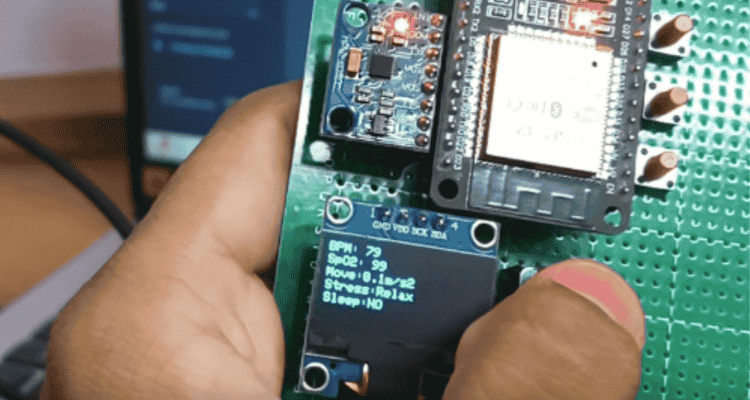
attachInterrupt(digitalPinToInterrupt(SOS_PIN), sosISR, FALLING); 5.8 OLED Display Output
The OLED displays real-time health data, ensuring standalone usability even without internet:
- Heart Rate (BPM)
- SpO₂ (%)
- Movement
- Stress Level
- Sleep State
- SOS Status
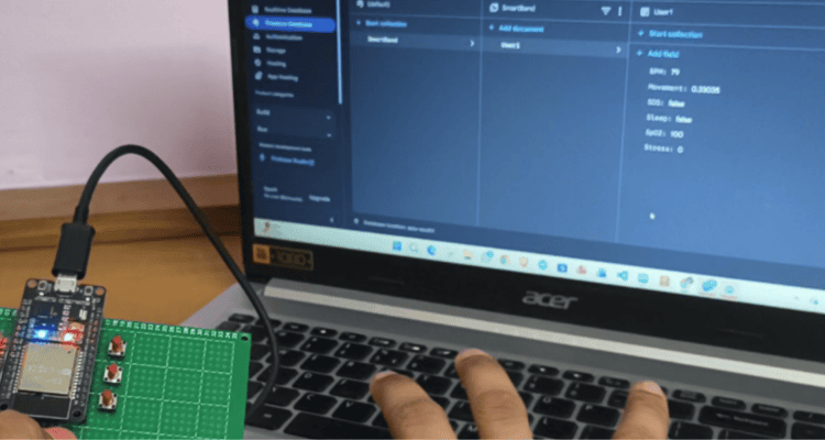
5.9 Firebase Cloud Data Upload
- Sensor data is uploaded every 2 seconds
- Data is stored in structured Firestore fields
SmartBand
└── User1
├── BPM
├── SpO2
├── Movement
├── Stress
├── Sleep
└── SOS
6. Web Dashboard & Emergency Response System
6.0 Purpose of This Code
This web application acts as the remote monitoring and emergency response interface. It:
- Displays real-time health data from ESP32
- Detects SOS automatically
- Fetches mobile phone GPS location
- Sends WhatsApp emergency alert with Google Maps link
- Stores phone location back to Firebase
6.1 System Architecture (Web Side)
ESP32 Smart Band
↓
Firebase Firestore (Cloud)
↓ (onSnapshot)
Web Dashboard (Live UI)
↓
Phone GPS + WhatsApp SOS
6.2 Firebase SDK Initialization
import { initializeApp } from "firebase-app.js"; import { getFirestore } from "firebase-firestore.js"; import { getAuth, signInAnonymously } from "firebase-auth.js"; Purpose:
- firebase-app → Initializes Firebase project
- firestore → Reads & updates health data
- auth → Enables anonymous access
6.3 Firebase Configuration
const firebaseConfig = { apiKey, authDomain, projectId }; Connects the web app to the same Firebase project used by ESP32.
6.4 Anonymous Authentication
signInAnonymously(auth); Advantages:
- No login UI required
- Secure access to Firestore
- Ideal for emergency dashboards
6.5 Real-Time Firestore Listener
const docRef = doc(db, "SmartBand", "User1"); onSnapshot(docRef, (docSnap) => { ... }); Key Feature:
- onSnapshot() enables real-time data updates
- Any ESP32 update reflects instantly on the webpage
6.6 Live Health Data Display
bpmEl.innerText = d.BPM ?? "--"; spo2El.innerText = d.SpO2 ?? "--"; moveEl.innerText = d.Movement.toFixed(2); ParameterSourceBPMMAX30102SpO₂MAX30102MovementMPU6050StressHRV AnalysisSleepMotion + BPMSOSButton Interrupt
6.7 SOS Detection Logic
if (d.SOS === true && !sosTriggered) { sosTriggered = true; triggerSOS(); } Why important:
- Prevents repeated SOS alerts
- Ensures only first press activates emergency sequence
6.8 SOS Visual Alert
- SOS text blinks every 500 ms
- Immediate attention for caretakers
setInterval(() => { ... }, 500); 6.9 Phone GPS Location Fetching
navigator.geolocation.getCurrentPosition(...) Why Phone GPS?
- ESP32 has no GPS module
- Higher accuracy
- Works indoors and outdoors
6.10 Google Maps Location Link
https://maps.google.com/?q=lat,lon - Clickable live map
- Works on all devices
6.11 Saving Phone Location to Firebase
await updateDoc(docRef, { PhoneLat, PhoneLon, PhoneMap }); Benefits:
- Permanent emergency record
- Accessible by doctors, caretakers, and admins
6.12 Automatic WhatsApp SOS Alert
window.open( `https://wa.me/number?text=message`, "_blank" ); Message Includes:
- SOS Alert
- User needs help
- Google Maps live location
- WhatsApp opens automatically
- No button click required
- Website remains active


