
By Ojas Chanakya, Aniruddh Viswananthan
We have developed a smart home energy management system prototype that divides the house into sectors and efficiently chooses which sector is powered by what energy source. The reason why we developed this project was that in India, the adoption of renewable energy is still not widespread, despite the subsidies and encouragement by the government. This is due to the unreliability of solar power, and user's preference to have an uninterrupted supply. The solution currently deployed for this is the use of net metering, i.e. sending the energy back to the power grid. While this seems good on paper, in India, where many towns still face power cuts, this system does not even allow users to use their own generated energy. A middle ground is needed, and hence we have developed this project.
This project aims to ensure that the user has an uninterrupted power supply, while smartly switching the supply of sectors from the renewable source to the power grid, depending upon the power generated by the renewable source. The system uses AC power meters to constantly monitor the power generated by the renewable source, and the power being consumed by the sectors. If all sectors can be powered by renewable energy, it prioritizes that. If both sectors cannot be powered, it prioritizes the sector that is consuming higher energy, ensuring savings for the user. The system also integrates a backup battery, which can supplement the renewable source and power the house for some time in case both sources are insufficient. The energy management system also decides when to utilize the battery and when to charge it.
To realize this, we have chosen the ESP32S3 BOX3 development board, as its onboard screen, buttons, Wi-Fi, Bluetooth and accessories provide an excellent platform to quickly build prototypes.
Components Required
| Component Name | Quantity | Datasheet/Link |
| Peacefair PZEM-004T | 4 | - |
| 7Semi UART MUX-DEMUX breakout board | 1 | - |
| 5V-3V3 Bidirectional Level Shifter | 2 | - |
| ESP32S3 BOX3 | 1 | - |
| 12V DC-AC Inverter | 1 | - |
| 3S Lithium-Ion Battery | 1 | - |
| 4 Channel relay module | 2 | - |
Circuit Diagram

Hardware Assembly
As you can see in the above circuit diagram, this system uses 2 sources: the AC Power grid and the renewable source represented by the 12V Li-Ion Battery.
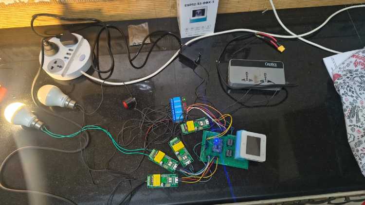
The PZEM-004T power sensors are used throughout the system to monitor the power drawn by these sources and the 2 sectors.
- To connect the AC power grid, the wires coming from the power socket are run through the power sensor, and connected to one terminal of the source switching relays.
- To connect the renewable energy source, the battery is connected to a relay, so as to control its output, and the output of the relay is connected to the Ceptics DC-AC converter module, which acts as an Inverter, converting the 12V DC to 240V 50Hz AC
- This AC supply is then fed through another power sensor and connected to the other terminal of source switching relays.
- Both the sectors, here represented by lightbulbs are connected to the outputs of the source switching relays
The signal connections of the ESP32S3 Box are as follows:
- The PZEM-004T power sensors work on 5VDC logic, while the esp32 operates on 3v3 logic, so bidirectional level shifters are used to safely interface the sensors and relays with the ESP32S3
- The UART1 port of the ESP32 is used to interface with the sensors. this is connected to the UART MUX-DEMUX board by 7semi.
- GPIO 11 and 12 are connected to the A and B pins of the MUX-DEMUX board, allowing for selection of UART slave.
| Logic of 'A' | Logic of 'B' | UART Output Selected |
| 0 | 0 | UART -1 |
| 0 | 1 | UART -2 |
| 1 | 0 | UART -3 |
| 1 | 1 | UART -4 |
- Once selected, the sensor is read and the data is used by the esp32 to switch between sources.
- GPIO 40, 41, and 13 are used to switch the 2 source switching relays, and the relay controlling the output of the battery.
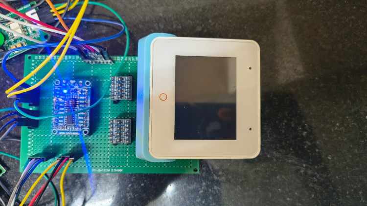
Prototype PCB:
- Because this project uses multiple level shifters and sensors, wiring them all on a breadboard would lead to a wiring mess. So all the components are soldered onto a prototype PCB
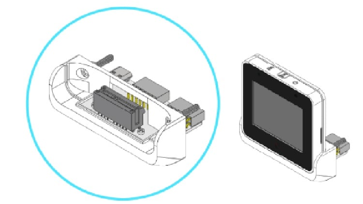
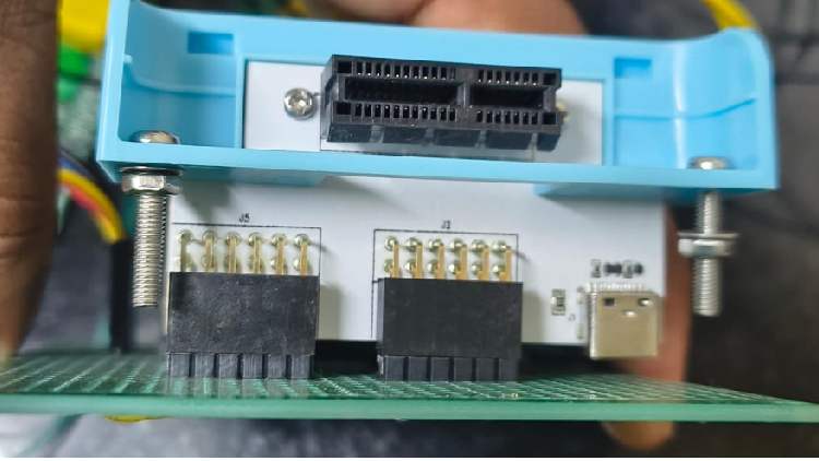
- To connect the ESP32S3 BOX board to the PCB, use the included Bracket which is intended to allow the ESP32S3 box to connect to PCBs.
- Power is provided to the level shifters, UART MUX-DEMUX board and ESP32 by using a 5V AC-DC converter, which is connected to the PCB
Code Explanation
The ESP-IDF has been used to program the ESP32S3 Box development board provided by Digikey. FreeRTOS has been used to enable multithreading and optimal use of the ESP32's computing power. The main elements of the code are:
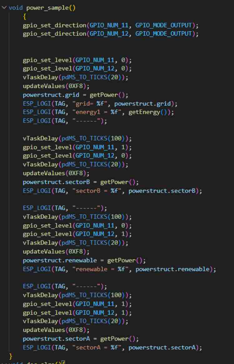
1. Power_sample function: This function is used to measure the 4 important power values: the power generated by the renewable source, the power drawn by sector A and sector B, and the power being drawn from the power grid. It also measures the energy in KWh drawn from the power grid, which can be used to determine how much energy has been saved. The function also controls the UART MUX-DEMUX module, using GPIOs to select which sensor is currently being read.
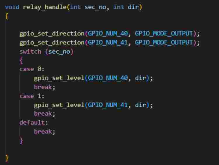
2. Relay_handle function: This function is used to control the relays, which enable switching between sources.
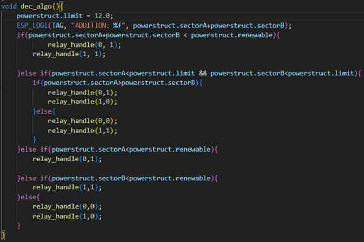
3. Dec_algo function: This function contains the decision algorithm that the system uses to decide which source powers which sector. The algorithm prioritizes renewable energy and savings, powering as many sectors as possible from renewable energy, and in case all sectors cannot be powered by renewable energy, it prioritizes the sectors drawing the most energy, so as to save money on the energy bill.
GitHub Repository


