
By Thejas A V
PROJECT OVERVIEW
Smart Home Automation using ESP32-S3-BOX3 as WiFi Access Point
I have built a local WiFi-based smart home system that works without internet.
- The ESP32-S3-BOX3 creates its own WiFi network (Access Point mode).
- my MIT App connects to that WiFi with speech recognition module.
- App sends HTTP commands.
- ESP32 receives commands and controls relays.
- Relays switch AC loads (Light + Fan).
No cloud. No router. Pure local control. Clean.
Overview
This project implements a WiFi-based Smart Home Automation System where an ESP32-S3-BOX3 operates in Access Point (AP) mode to create a private wireless network.
A mobile application developed using MIT App Inventor connects to this network and sends HTTP-based control commands to the ESP32. The ESP32 processes these commands and controls electrical appliances (light and fan) through relay modules.
The system works without internet connectivity, making it suitable for remote or local-only environments.
Main Concept
- ESP32-S3-BOX3 creates its own WiFi network
- Mobile app connects to that WiFi
- App sends control commands via HTTP
- ESP32 receives commands and switches relays
- Relays control AC loads (Light & Fan)
ESP32-S3-BOX3 Smart Home Controller
Our ESP32-S3-BOX3 is acting as:
- Main Controller
- WiFi Access Point
- Local Web Server
- Touchscreen Control Panel
- Environment Monitor
It’s basically the brain + control panel of your smart home.
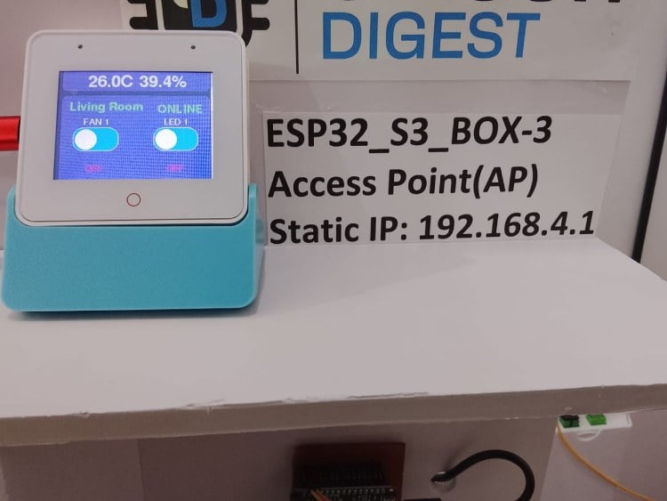
Screen 1 – Environment Monitoring
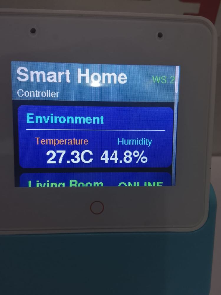
Display shows:
Temperature: 27.3°C
Humidity: 44.8%
Section name: Environment
Header: Smart Home Controller
WS: 2 (WebSocket clients connected)
That “WS: 2” is the key thing.
What is WebSocket in My Project?
WebSocket is a real-time full-duplex communication protocol.
Unlike normal HTTP:
HTTP WebSocket One request → One response Continuous two-way connection Slow for live data Instant live updates Client asks every time Server pushes automatically
we are using WebSocket so:
- ESP32 pushes sensor data live
- App receives instantly
- No page refresh required
- No delay
This means:
- ESP32 is reading data from a DHT sensor.
- Sensor values are displayed in real-time on the touchscreen.
- monitoring room climate locally.
This is are my IoT monitoring feature
Screen 2 – Living Room Control
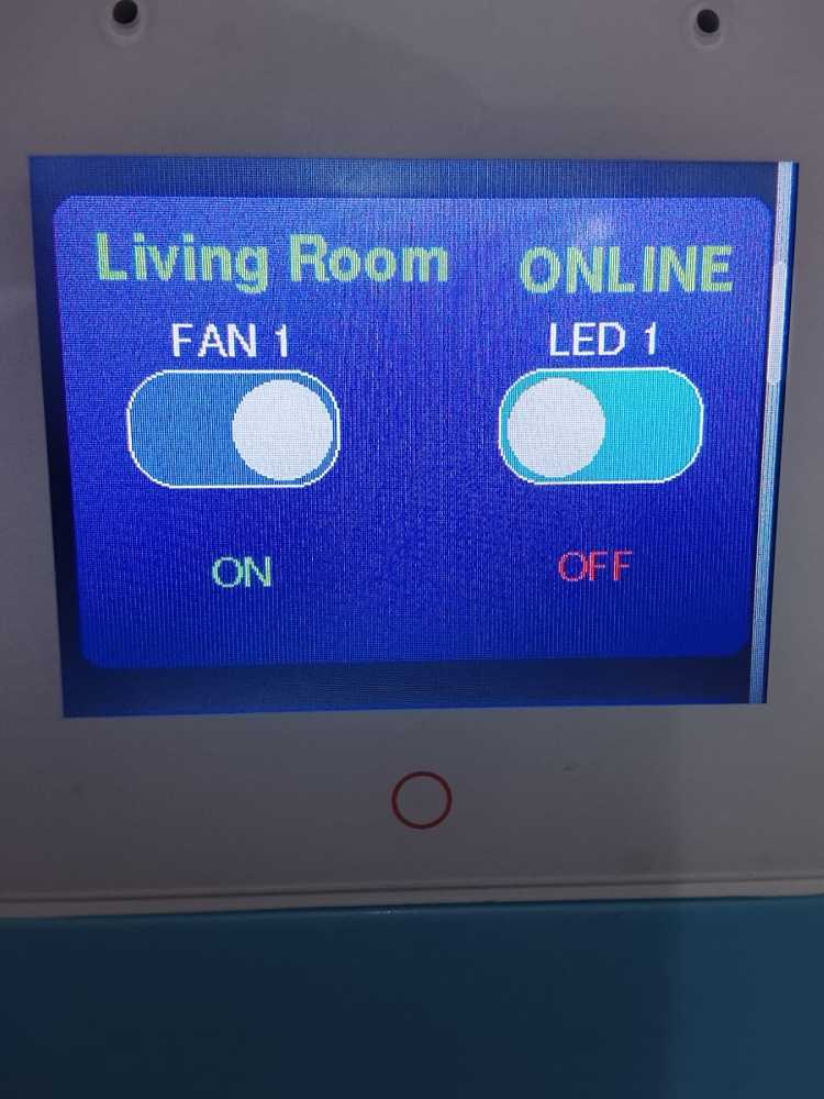
I have:
- Status: ONLINE
- FAN 1 toggle
- LED 1 toggle
- ON / OFF indicator
What this means:
- The living room node is connected to the ESP32 network.
- Relays are controlled via touch.
- Toggle switch UI updates based on device state.
So now control is possible:
- From mobile app
- From touchscreen panel
Screen 3 – Bedroom Control
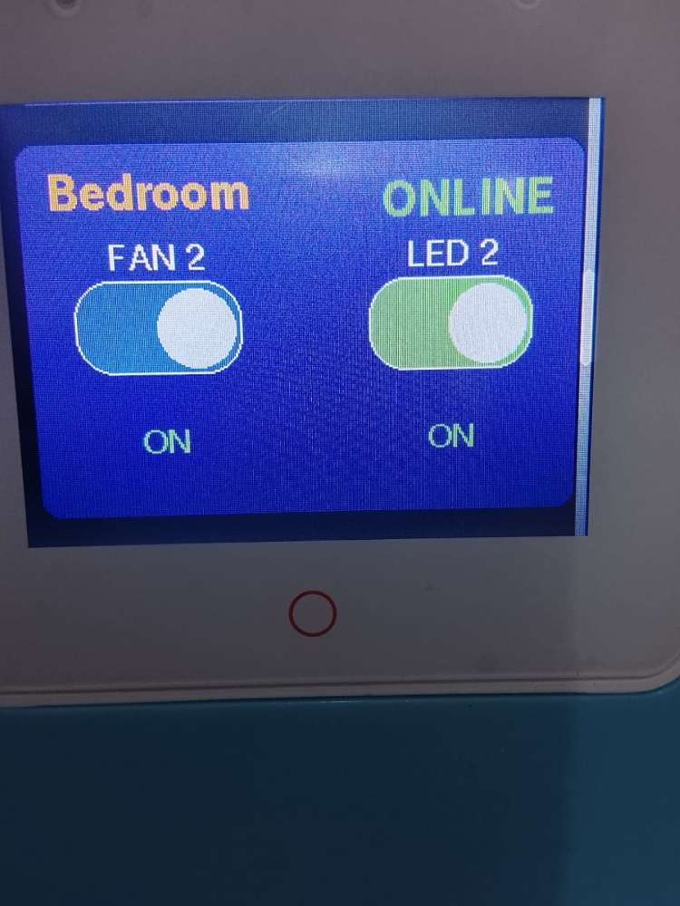
I have:
- Bedroom status: ONLINE
- FAN 2 control
- LED 2 control
- ON/OFF state indicator
This confirms:
- Multi-room architecture
- Each room has separate relay control
- System supports expansion
i have structured it properly.
Screen 4 – Network Information
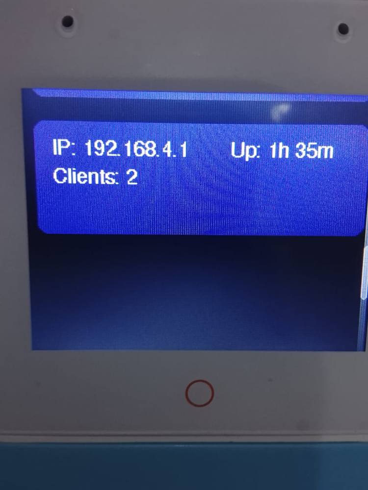
This part is very important for my project explanation:
It shows:
- IP Address: 192.168.4.1
- Clients Connected: 2
- Uptime: 1 hour 35 minutes
This confirms:
- ESP32-S3-BOX3 is running in Access Point mode.
- Mobile app + other node devices are connected.
- System is stable and running continuously.
Web Interface Explanation (PC and Mobile Access)
Overview
I developed a web-based control interface for my Smart Home Automation System. The interface is hosted on the ESP32-S3-BOX3, which operates in Access Point mode with the IP address:
192.168.4.1
This web interface allows me to monitor environmental parameters and control home appliances from both a PC and a mobile device without requiring internet connectivity.
Web Interface on PC
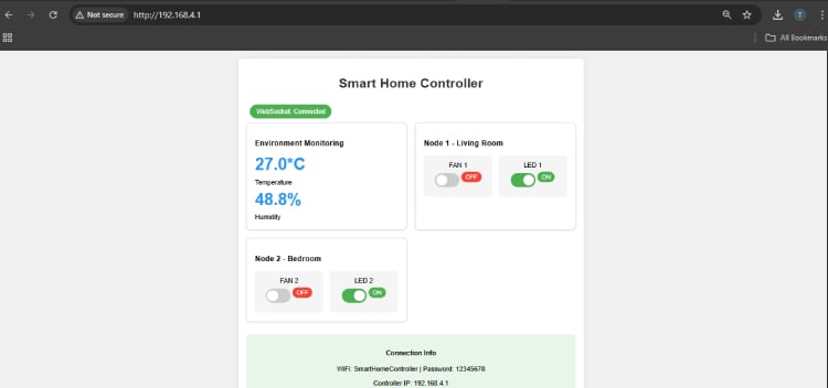
When I connect my computer to the ESP32 WiFi network and open a browser, I enter:
http://192.168.4.1
The browser loads the Smart Home Controller dashboard.
The interface displays:
1. Header Section
- Title: Smart Home Controller
- WebSocket Status: Connected
This confirms that real-time communication between the browser and ESP32 is active.
2. Environment Monitoring Section
This section shows:
- Temperature (e.g., 27.0°C)
- Humidity (e.g., 48.8%)
These values are received from the DHT sensor connected to NodeMCU and updated in real time using WebSocket communication.
3. Device Control Section
The dashboard contains control panels for:
- Node 1 – Living Room
- Fan 1
- LED 1
- Node 2 – Bedroom
- Fan 2
- LED 2
Each device has a toggle switch.
When I click a toggle:
- An HTTP request is sent to the ESP32.
- ESP32 processes the command.
- The corresponding NodeMCU activates the relay.
- The appliance turns ON or OFF.
- The interface updates instantly.
Web Interface on Mobile
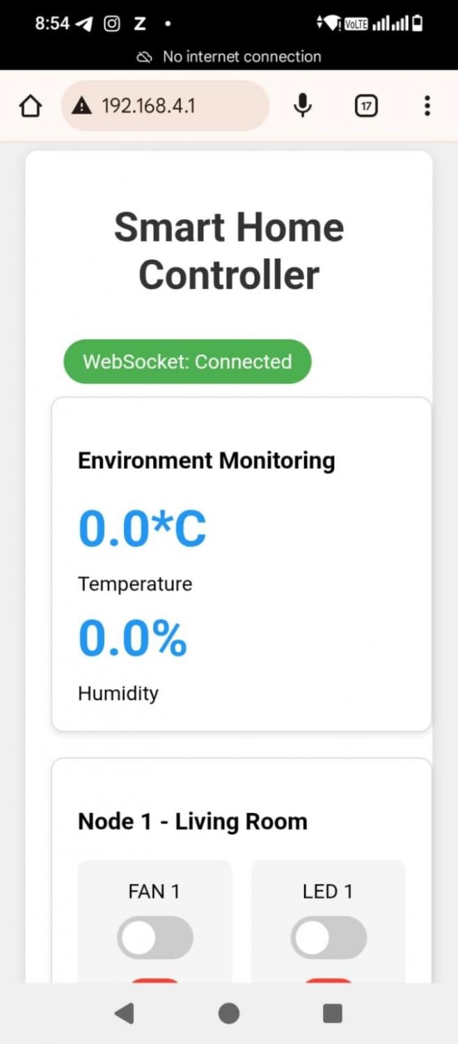
When I connect my mobile phone to the same ESP32 WiFi network and open a browser, I type:
192.168.4.1
The same web interface loads in a responsive format.
The layout automatically adjusts to mobile screen size. The elements are arranged vertically for easy interaction.
Features on Mobile:
- WebSocket connection status
- Real-time temperature and humidity
- Toggle switches for all devices
- Instant feedback on device status
Even though the phone shows “No Internet Connection,” the system works because it operates on a local WiFi network.
Communication Method Used
The web interface uses two protocols:
1.HTTP
Used when I toggle devices.
It sends control commands to the ESP32.
2.WebSocket
Used for:
- Live temperature updates
- Humidity updates
- Device status synchronization
- Connection status monitoring
This ensures real-time operation without refreshing the page.
Advantages of the Web Interface
- Works without internet
- Accessible from PC and mobile
- Real-time updates
- Responsive design
- Easy device control
- Local network security
Working Summary
When I open the web interface:
1.The browser connects to ESP32.
2.WebSocket connection is established.
3.Environmental data is displayed.
4.I control appliances using toggle switches.
5.Commands are sent instantly.
6.Devices respond in real time.
MIT App Inventor – Smart Home Automation App
Overview
I developed a mobile application using MIT App Inventor to control and monitor my Smart Home Automation System. The app connects to the ESP32-S3-BOX3 access point and allows me to:
- Control lights and fans
- Monitor temperature and humidity
- Use voice commands for automation
- Access the system without internet
The app works completely on a local WiFi network.
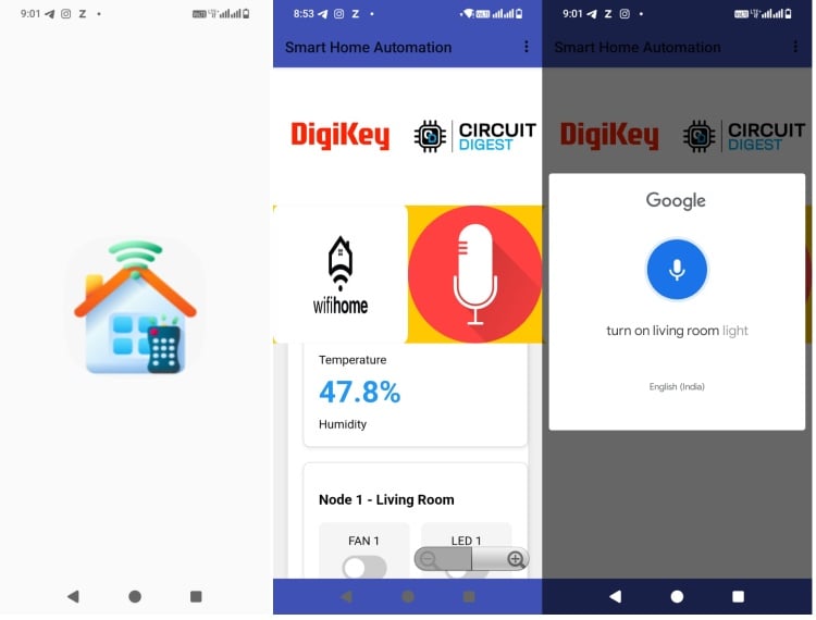
App Interface Explanation
1.Header Section
At the top of the app, I display:
“Smart Home Automation”
This represents the main control dashboard of my system.
2.Branding / Home Section
Below the header, I included:
- DigiKey and Circuit Digest logos (for project presentation)
- A WiFi Home icon
- A Microphone icon for voice control
This section provides a user-friendly and professional appearance.
3.Environment Monitoring Section
The app displays:
- Temperature
- Humidity
These values are received from the DHT sensor connected to the NodeMCU (D4 / GPIO2).When the ESP32 receives sensor data, it sends it to the app using WebSocket communication. The app updates values automatically without refreshing.
Voice Control Feature
The app includes a Speech Recognizer component.
When I press the microphone icon:
1.Google voice recognition opens.
2.I speak a command, for example:
- “Turn on living room light”
1.The app converts speech into text.
2.The text is compared using IF conditions.
3.Based on the command, the app sends an HTTP request to:
http://192.168.4.1/control?device=led1&state=on
1.The ESP32 processes the request.
2.The relay switches ON.
This allows hands-free device control.
Device Control Section
The app contains toggle buttons for:
Node 1 – Living Room
- Fan 1
- LED 1
Node 2 – Bedroom
- Fan 2
- LED 2
When I toggle a switch:
- The app sends an HTTP request to ESP32.
- ESP32 forwards the command to the respective NodeMCU.
- The relay activates.
- The device turns ON or OFF.
Communication Used in the App
The app uses two communication methods:
1. HTTP Protocol
Used for:
- Turning devices ON/OFF
- Sending control commands
2. WebSocket Protocol
Used for:
- Real-time temperature updates
- Humidity updates
- Device status synchronization
This ensures instant updates without delay.
Working Without Internet
Even if the phone shows “No Internet Connection,” the app works because:
- It connects to ESP32 WiFi (Access Point Mode)
- Communication happens locally
- No cloud server is required
This makes the system secure and independent.
Complete App Working Flow
1.connect my phone to ESP32 WiFi.
2. I open the MIT app.
3. The app connects to 192.168.4.1.
4. WebSocket connection is established.
5. Sensor data is displayed.
6. I control devices manually or via voice.
7. Commands are executed instantly.
Advantages of MIT App Inventor App
- Easy drag-and-drop development
- Voice-enabled control
- Real-time updates
- Works offline
- Simple user interface
- Expandable for more rooms/devices
Software Used for Programming
In my Smart Home Automation project, I used two main software platforms:
- Arduino IDE
- MIT App Inventor
Both software tools were used for different purposes in the system.
1. Arduino IDE
Purpose
I used Arduino IDE to program:
- ESP32-S3-BOX3 (Main Controller)
- NodeMCU (ESP8266) – Node 1 and Node 2
Why Arduino IDE?
- Easy to use
- Supports ESP32 and ESP8266 boards
- Large library support
- Simple C/C++ based programming
What I Programmed in Arduino IDE
For ESP32-S3-BOX3:
- WiFi Access Point setup
- Web Server (HTTP)
- WebSocket server
- Touchscreen GUI
- Command processing logic
For NodeMCU:
- WiFi connection to ESP32
- Relay control using GPIO
- DHT sensor reading (D4 / GPIO2)
- Sending sensor data to main controller
Libraries Used
- WiFi library
- WebServer library
- WebSockets library
- DHT sensor library
- ESP8266WiFi (for NodeMCU)
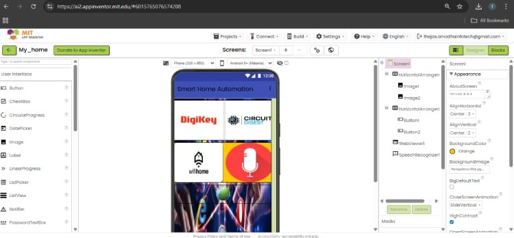
2. MIT App Inventor
.jpg)
Purpose
I used MIT App Inventor to develop the mobile application for:
- Controlling devices
- Monitoring temperature and humidity
- Voice-based control
Why MIT App Inventor?
- Drag-and-drop interface
- No complex coding required
- Easy integration of Web and Speech components
- Fast Android app development
Components Used
Designer Section:
- Buttons
- Images
- Labels
- Web component
- SpeechRecognizer component
Blocks Section:
- IF conditions for voice commands
- HTTP request blocks
- Web component to send commands
- Text comparison logic
Components Required
| Component Name | Quantity | Datasheet/Link |
| ESP32-S3-BOX-3 | 1 | View Datasheet |
| ESP8266-DEVKITC-02U-F | 2 | View Datasheet |
| TS0010D 2 CHANNEL RELAY | 2 | View Datasheet |
| ST0248 DHT11 TEMPERATURE AND HUMIDITY SENSOR | 1 | View Datasheet |
| ZW-FF-30 ZIPWIRE FEMALE-TO-FEMALE, 30CM | 1 | View Datasheet |
Circuit Explanation (Both Nodes Using NodeMCU – ESP8266)
Both Node 1 and Node 2 use:
- NodeMCU (ESP8266)
- 2-Channel Relay Module
- 5V Power Adapter
- AC Light & Fan
- Node 1 also includes DHT Sensor
1.Power Supply Section
- A 5V, 2A adapter supplies power.
- 5V is connected to:
- NodeMCU VIN (or 5V pin)
- Relay module VCC
- GND from adapter connected to:
- NodeMCU GND
- Relay GND
2. NodeMCU to Relay Connection
Two GPIO pins of NodeMCU are connected to:
- D1 → Relay IN1
- D2 → Relay IN2
(Exact pins may vary depending on your code.)
When NodeMCU outputs LOW or HIGH:
- Relay coil energizes
- Internal switch changes state
- AC load turns ON or OFF
Most relay modules for NodeMCU are active LOW.
Meaning:
- LOW → Relay ON
- HIGH → Relay OFF
Very important for viva
3. AC Load Connection
Each relay channel controls one AC appliance.
For each appliance:
- AC Phase → Relay COM
- Relay NO → Appliance
- Neutral → Direct to Appliance
When relay is ON:
- COM connects to NO
- Current flows
- Appliance turns ON
When relay is OFF:
- Circuit opens
- Appliance turns OFF
4. Node 1 – DHT Sensor Connection

Node 1 has an extra component: DHT sensor.
Connections:
- VCC → 3.3V (recommended for ESP8266)
- GND → GND
- DATA → One digital GPIO (e.g., D4)
The NodeMCU reads:
- Temperature
- Humidity
This data is:
- Sent to ESP32-S3-BOX3
- Displayed on touchscreen
- Transmitted via WebSocket
- Shown in mobile app
Complete Working Flow
1.Power supplied to NodeMCU
2.NodeMCU connects to ESP32 Access Point
3.Waits for HTTP command
4.When command received:
- Changes GPIO state
- Relay switches
- Light/Fan turns ON/OFF
- 5.Node 1 also reads DHT data and sends it to main controller
Why Relay is Used?
Relay provides:
- Electrical isolation
- Protects NodeMCU (3.3V logic)
- Safely switches 230V AC load
Never connect AC directly to NodeMCU.
1.Node 2 Circuit Diagram Explanation
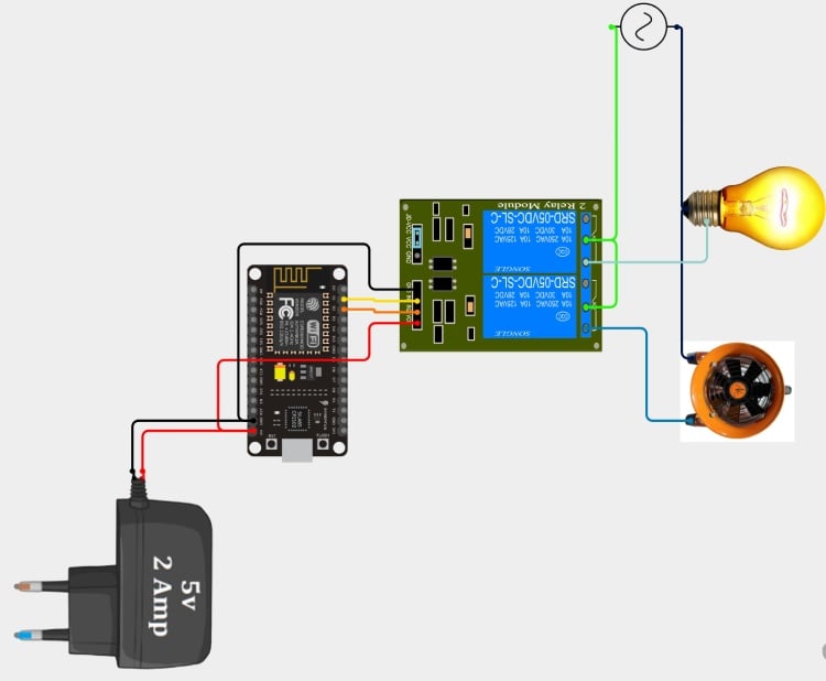
Components Used:
- ESP32 board
- 2-Channel Relay Module
- 5V 2A Power Adapter
- AC Bulb
- AC Fan
Power Supply Section
- A 5V, 2A adapter supplies power.
- 5V is connected to:
- ESP32 VIN/5V pin
- Relay module VCC
- GND of adapter connected to:
- ESP32 GND
- Relay GND
This ensures common ground for proper switching.
ESP32 to Relay Connection
Two GPIO pins from ESP32 are connected to:
- IN1 → Relay Channel 1
- IN2 → Relay Channel 2
When ESP32 outputs HIGH or LOW:
- Relay switches ON/OFF
- AC appliance is controlled
AC Load Connection
The relay module controls the AC phase line.
For each appliance:
- AC Phase → Relay COM
- Relay NO → Appliance
- Neutral → Direct to Appliance
When relay activates:
- COM connects to NO
- Circuit completes
- Light or Fan turns ON
When relay deactivates:
- Circuit opens
- Appliance turns OFF
Final Summary
Both Node 1 and Node 2 use NodeMCU (ESP8266) as control units.
They receive commands over WiFi, control relay modules through GPIO pins, and switch AC appliances like light and fan.
Node 1 additionally monitors temperature and humidity using a DHT sensor.
Hardware Assembly
AC Wiring to Relay – Explanation
Overview
In my system, each node controls two AC loads:
- Light
- Fan
For each node, I used a two-socket box.
The wiring is done such that:
- Neutral (N) is common for both sockets
- Phase (P) is controlled through relay
- Earth (E) is directly connected for safety
Image 1 – Two Socket Box Internal Wiring
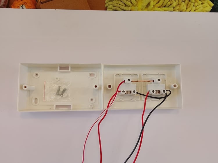
Neutral Wiring (N)
- Neutral wire is common for both sockets.
- It is directly connected using a connector block.
- Neutral does not pass through the relay.
- Both light and fan receive neutral continuously.
This means neutral is always available at the load.
Phase Wiring (P)
- Phase wire is routed to the Common (C) terminal of each relay.
- When relay is OFF → No connection to load.
- When relay is ON → Common connects to NO (Normally Open).
- Phase flows to socket.
- Device turns ON.
So relay controls only the phase line.
Earth Wiring (E)
- Earth wire is connected directly to both sockets.
- It does not pass through the relay.
- It provides safety grounding.
Very important for electrical safety.
Image 2 – Back Side Relay Wiring
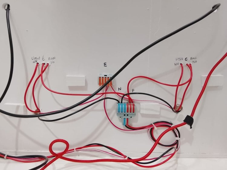
i have labeled for refrence:
- NO → Normally Open
- C → Common
- P → Phase
- N → Neutral
- E → Earth
Phase Connection
- Main phase (P) enters the relay board.
- Phase wire is connected to Common (C) of both relays.
- When relay activates:
- C connects to NO.
- Phase flows to output terminal.
- Current reaches light or fan.
Current Flow When Relay ON
Phase (P)
↓
Relay Common (C)
↓
Relay Normally Open (NO)
↓
Socket
↓
Load (Light/Fan)
↓
Neutral (N)
When relay OFF:
- C and NO are disconnected.
- No phase supply.
- Device OFF.
Why Only Phase Is Switched?
In AC systems:
- Neutral should remain common.
- Switching phase ensures safe disconnection.
- If neutral is switched instead, the appliance may remain live internally.
So controlling phase is correct and safe design practice.
Both Nodes Use Same Wiring
- Same 2-socket box structure
- Same relay wiring
- One relay for Light
- One relay for Fan
- Common neutral shared
- Phase controlled via relay
Safety Considerations
- Relay provides isolation between:
- Low voltage NodeMCU (3.3V logic)
- High voltage AC (230V)
- Earth connected directly to sockets
- Proper connectors used
- Phase separated clearly
Final Working Summary
- Neutral is common for both sockets.
- Phase is connected to Common terminal of relay.
- When relay activates, phase connects to NO terminal.
- Current flows through load.
- Light or fan turns ON.
- Earth is directly connected for protection.
NodeMCU Breakout Board Explanation
Overview
I designed and fabricated a custom breakout board using a general-purpose PCB (perfboard) to interface the NodeMCU with:
- Relay module
- DHT sensor
- Power supply
- External connections
This breakout board simplifies wiring and makes the system stable and modular for both Node 1 and Node 2.
Top Side (Component Side)
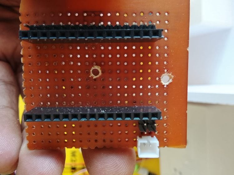
- Two long female header connectors are soldered.
- These headers allow direct mounting of the NodeMCU module.
- A 2-pin/3-pin connector is provided at the bottom for:
- Sensor connection
- Relay signal connection
- Power lines
Purpose:
- Easy plug-and-play mounting
- Secure mechanical support
- Clean wiring layout
Bottom Side (Solder Side)
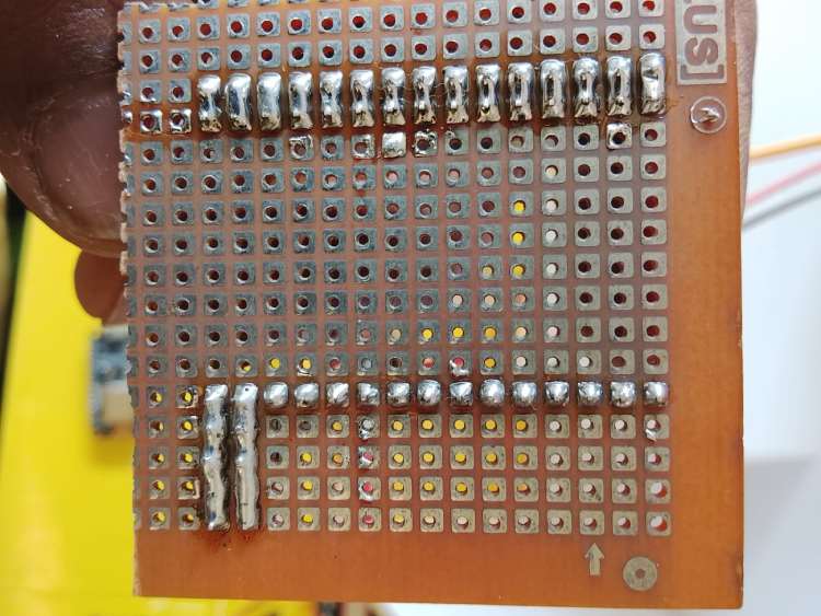
I have:
- Proper soldered header pins
- Bridged solder tracks forming power rails
- Common ground connections
- Connected GPIO breakout lines
you can see:
- Horizontal solder bridges used as power rails (5V and GND)
- Vertical solder bridges used for signal distribution
This creates a simple custom PCB routing system.
Power Distribution
You created:
- One common 5V rail]
- One common GND rail
These rails distribute power to:
- Relay module
- DHT sensor
- NodeMCU VIN
This avoids loose wires and improves reliability.
Sensor Connection (Node 1)
For Node 1:
- DHT DATA → D4 (GPIO2)
- VCC → 3.3V
- GND → GND rail
The breakout board provides stable connection points for these pins.
Relay Connections
For both nodes:
- GPIO pins (D1, D2 etc.) routed to terminal connectors
- These connect to relay IN1 and IN2
- 5V and GND also routed to relay module
This allows:
- Clean signal routing
- Reduced wiring errors
- Better troubleshooting
Access Point Node Explanation
ESP32-S3-BOX-3
In my Smart Home Automation system, I use the ESP32-S3-BOX-3 as the main Access Point (AP) node. This device acts as the central controller and communication hub for the entire system.
Access Point Configuration
I configured the ESP32 in Access Point mode, which allows it to create its own WiFi network instead of connecting to an external router.
I assigned a static IP address:
192.168.4.1
This IP address is used to access the system through:
- Web browser
- Mobile application
- Internal node communication
By using Access Point mode, I ensured that my system works without internet connectivity.
Role of the Access Point Node
The ESP32-S3-BOX-3 performs multiple functions in my system:
1. WiFi Network Creator
I use the ESP32 to:
- Create a local WiFi network
- Allow NodeMCU nodes to connect
- Allow mobile phone and PC to connect
- Provide local communication between devices
2 .Web Server
I programmed the ESP32 to host a web server.
When I open a browser and type:
http://192.168.4.1
The Smart Home dashboard loads.
When I toggle a device:
- An HTTP request is generated.
- The ESP32 processes the request.
- The corresponding node receives the command.
3.WebSocket Server
I implemented WebSocket communication to achieve real-time updates.
Using WebSocket, I:
- Receive live temperature data
- Receive humidity data
- Update device status instantly
- Avoid refreshing the webpage
This makes the system fast and responsive.
4.Touchscreen Controller
The ESP32-S3-BOX-3 includes a built-in touchscreen display.
I use it to:
- Display temperature and humidity
- Show node connection status (ONLINE/OFFLINE)
- Control lights and fans manually
- Monitor system uptime and client count
This allows local physical control without using a mobile phone.
Working Process
1. I power on the ESP32.
2. It creates a WiFi Access Point.
3. NodeMCU devices connect to it.
4. I connect my mobile or PC to the same network.
5. I send commands through app, web, or touchscreen.
6. The ESP32 processes and forwards commands.
7. Device status updates in real time.
NODE-1 – Living Room
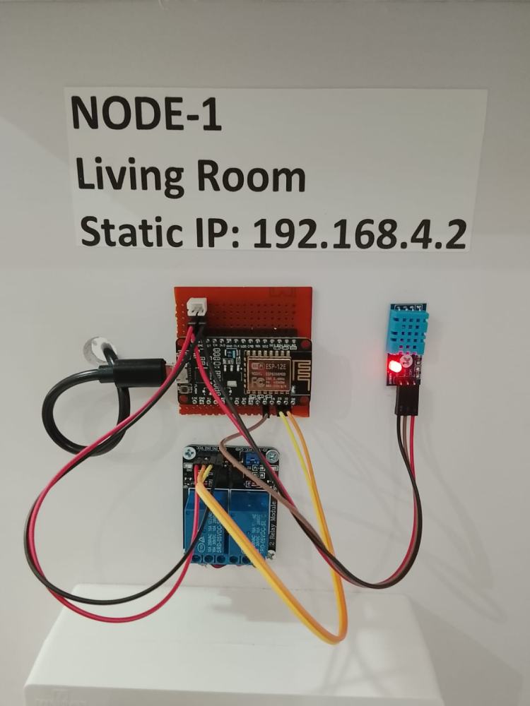
Hardware Architecture Explanation
In my Smart Home Automation system, Node-1 is installed in the Living Room and is responsible for:
- Controlling Light
- Controlling Fan
- Monitoring Temperature
- Monitoring Humidity
I assigned it a static IP address: 192.168.4.2 so that the Access Point (ESP32-S3-BOX-3) can communicate with it reliably.
1.Main Controller – NodeMCU (ESP8266)
At the core of Node-1, I use a NodeMCU (ESP8266) microcontroller.
I use it to:
- Connect to ESP32 Access Point
- Receive ON/OFF commands
- Control relay module
- Read DHT sensor data
- Send sensor data back to AP
It acts as a distributed control unit in my system.
2. DHT Sensor Module
I connected a DHT temperature and humidity sensor to Node-1.
Connections:
- VCC → 3.3V
- GND → GND
- DATA → D4 (GPIO2)
The DHT sensor measures:
- Temperature (°C)
- Humidity (%)
I read the sensor data using the DHT library and transmit the values to the ESP32 Access Point for display on:
Touchscreen panel
Web interface
Mobile app
3. Relay Module (2-Channel)
I use a 2-channel relay module to control:
Relay 1 → Living Room Light
Relay 2 → Living Room Fan
GPIO Connections:
- D1 → Relay IN1
- D2 → Relay IN2
The relay module switches the phase line (P) of the AC supply.
When I enable a relay:
- Common (C) connects to NO (Normally Open)
- Phase flows to appliance
- Light or fan turns ON
4. Power Supply Section
Node-1 is powered using:
- 5V supply to NodeMCU (via USB)
- 5V to relay module
- 3.3V from NodeMCU to DHT sensor
I created a custom breakout board to:
- Distribute power
- Provide stable connections
- Reduce loose wiring
5. Network Architecture
Node-1 works in Station (STA) mode.
I configured it to:
- Connect to ESP32 Access Point
- Use static IP: 192.168.4.2
- Wait for HTTP commands
When ESP32 sends a command:
- NodeMCU receives request
- Processes device control
- Switches relay
- Sends updated status
Working Flow of Node-1
1.I power ON Node-1.
2.It connects to ESP32 Access Point.
3.It initializes DHT sensor.
4.It waits for control commands.
5.When command is received:
- GPIO output changes.
- Relay activates.
- Appliance turns ON/OFF.
7.It periodically sends temperature and humidity data.
Hardware Architecture Summary
Node-1 consists of:
- NodeMCU (Processing + WiFi)
- DHT Sensor (Monitoring Unit)
- 2-Channel Relay (Switching Unit)
- Breakout Board (Power Distribution)
- AC Socket Box (Load Interface)
This architecture allows Node-1 to function as an intelligent distributed control and monitoring unit within the smart home network.
NODE-2 – Bedroom
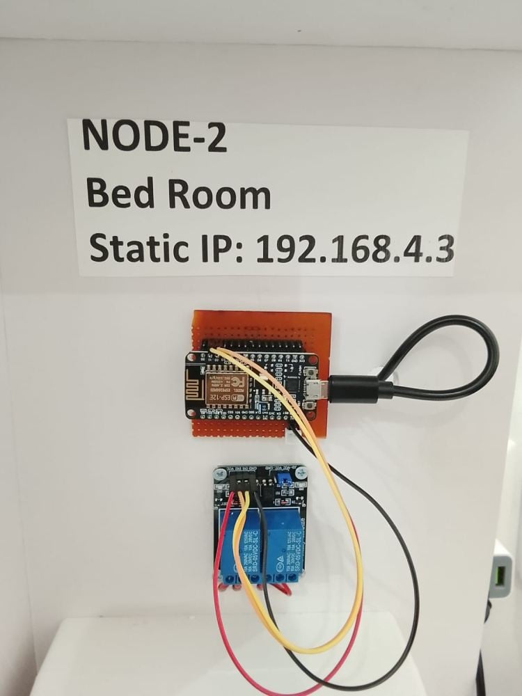
Hardware Architecture Explanation
In my Smart Home Automation system, Node-2 is installed in the bedroom and is responsible for controlling two AC loads:
- Bedroom Light
- Bedroom Fan
I assigned it a static IP address: 192.168.4.3 to ensure reliable communication with the ESP32 Access Point.
1.Main Controller – NodeMCU (ESP8266)
At the core of Node-2, I use a NodeMCU (ESP8266) mounted on a custom breakout board.
I use it to:
- Connect to the ESP32 Access Point (WiFi STA mode)
- Receive control commands
- Drive the relay module
- Send status updates back to the main controller
The NodeMCU acts as a distributed control unit within the system.
2.Custom Breakout Board
I fabricated a perfboard-based breakout board to:
- Mount the NodeMCU securely
- Provide organized GPIO routing
- Distribute 5V and GND lines
- Reduce loose wiring
This improves stability and makes the node modular and reusable.
3.2-Channel Relay Module
I connected a 2-channel 5V relay module to control:
- Relay 1 → Bedroom Light
- Relay 2 → Bedroom Fan
GPIO connections:
- D1 → IN1
- D2 → IN2
The relay switches only the phase (P) line of the AC supply.
When I activate a relay, Common (C) connects to Normally Open (NO), allowing current to flow to the appliance.
4. Power Architecture
- NodeMCU powered via Micro-USB (5V)
- Relay module powered from 5V
- Common ground shared across system
The NodeMCU internally regulates 5V to 3.3V for the ESP8266.
Working Process
1.I power on Node-2.
2.It connects to ESP32 AP (192.168.4.1).
3.It waits for HTTP commands.
4.When a command is received, it switches the corresponding relay.
5.The appliance turns ON or OFF.
Code Explanation
This is a comprehensive Smart Home Controller application for ESP32-S3-BOX3 with touch display. Let me explain it block by block:
1. Header Files & Libraries
cpp
#include <Arduino.h>        // Core Arduino framework
#include <Wire.h>          // I2C communication
#include <LGFX_AUTODETECT.hpp>  // Auto-detection for LovyanGFX
#include <LovyanGFX.hpp>   // Graphics library for display
#include <WiFi.h>          // WiFi functionality
#include <WebServer.h>     // HTTP web server
#include <HTTPClient.h>    // HTTP client for API calls
#include <ArduinoJson.h>   // JSON parsing
#include <WebSocketsServer.h>  // Real-time WebSocket communication
These libraries provide display, networking, web interface, and JSON handling capabilities.
2. Display & UI Configuration
cpp
#define SCREEN_WIDTH  320   // Display dimensions
#define SCREEN_HEIGHT 240
// UI Layout Constants - defines heights for different sections
#define TOTAL_HEIGHT 1100   // Total scrollable height
#define HEADER_HEIGHT 70    // Header section
#define SENSOR_HEIGHT 120   // Temperature/humidity panel
#define NODE1_HEIGHT 200    // First node controls
#define NODE2_HEIGHT 200    // Second node controls
#define INFO_HEIGHT 100     // Bottom info panel
Defines the UI layout with scrollable content taller than the screen.
3. Color Definitions
cpp
#define COLOR_BG      0x1082      // Background color
#define COLOR_HEADER  0x1E3A8A    // Header blue
#define COLOR_PANEL   0x1E40AF    // Panel blue
// ... other color constants
16-bit RGB565 color codes for UI elements.
4. Network Configuration
cpp
const char* AP_SSID = "SmartHomeController";  // WiFi AP name
const char* AP_PASSWORD = "12345678";         // WiFi password
String node1IP = "192.168.4.2";               // NodeMCU 1 IP
String node2IP = "192.168.4.3";               // NodeMCU 2 IP
Sets up the ESP32 as a WiFi Access Point and defines IPs for connected NodeMCUs.
5. Device State Structure
cpp
struct DeviceState {
 bool fan1 = false;       // Fan 1 status
 bool led1 = false;       // LED 1 status
 bool fan2 = false;       // Fan 2 status
 bool led2 = false;       // LED 2 status
 float temperature = 0.0; // Current temperature
 float humidity = 0.0;    // Current humidity
 bool node1Connected = false;  // Node 1 connection status
 bool node2Connected = false;  // Node 2 connection status
};
Tracks the current state of all devices and sensors.
6. Touch & Scrolling Variables
cpp
int scrollOffset = 0;            // Current scroll position
bool touchActive = false;        // Whether touch is active
uint16_t touchStartX = 0;        // Touch starting X coordinate
uint16_t touchStartY = 0;        // Touch starting Y coordinate
unsigned long touchStartTime = 0;// When touch started
bool isTap = true;              // Whether current touch is a tap
Manages touch input and scrolling functionality.
7. HTML Page (Web Interface)
A complete HTML/JavaScript web interface that:
- Displays temperature/humidity
- Shows device status with toggle switches
- Connects via WebSocket for real-time updates
- Provides mobile-responsive layout
8. setup() Function
Initialization sequence:
1.Serial Monitor - Starts debug output
2.Display - Initializes LCD with startup screen
3.WiFi AP - Sets up ESP32 as access point
4.WebSocket Server - Starts on port 81 with event handlers
5.Web Server - Sets up HTTP routes:
- GET / - Serves HTML page
- GET /control - Controls devices via HTTP
- GET /status - Returns JSON state
- GET /debug - Returns debug info
Initial UI Draw - Displays first screen
9. loop() Function
Main program loop:
1.Handles HTTP client requests
2.Processes WebSocket messages
3.Checks node connection status every 10s
4.Fetches DHT sensor data every 5s
5.Processes touch input
6.Small delay to prevent watchdog reset
10. Core Functions
drawUI() - Renders the display
- Draws all UI sections with scroll offset
- Sections: Header, Sensor Panel, Node 1 Controls, Node 2 Controls, Info Panel
- Updates WebSocket client count and connection status
- Calls drawScrollBar() for scrollable content
drawSwitch() - Draws toggle buttons
- Creates visual toggle switches with labels
- Changes color based on state (on/off)
- Only draws if visible on screen (optimization)
handleTouch() - Processes touch input
- Distinguishes between taps (button presses) and drags (scrolling)
- Updates scroll position for drag gestures
- Calls handleButtonPress() for taps
handleButtonPress() - Handles button taps
- Maps touch coordinates to button regions
- Toggles device states (fans/LEDs)
- Sends control commands to NodeMCUs
- Broadcasts updates via WebSocket
checkNodeStatus() - Monitors connections
- Pings NodeMCUs to check connectivity
- Updates connection status indicators
- Redraws UI if status changes
fetchDHTData() - Gets sensor data
- Fetches temperature/humidity from Node 1
- Updates display with new values
- Only attempts if node is connected
controlNode1/2Device() - Controls devices
- Sends HTTP requests to NodeMCUs
- Turns fans/LEDs on/off
- Includes error handling for failed requests
Key Features:
1. Dual Interface
- Touch Display: Local control with visual feedback
- Web Interface: Remote control from any device
2. Real-time Communication
- WebSocket for instant updates between web and display
- HTTP API for device control
3. Robust Error Handling
- Connection monitoring for NodeMCUs
- Timeouts for HTTP requests
- Fallback behavior when nodes disconnect
4. Efficient Display Updates
- Partial redraws based on scroll position
- Optimized touch detection
- Smooth scrolling experience
5. Scalable Architecture
- Can add more NodeMCUs easily
- Modular UI components
- JSON-based communication
This code creates a complete smart home controller with both local (touchscreen) and remote (web) control capabilities, real-time updates, and robust error handling.
Node 1: code
This is the NodeMCU 1 (Living Room) code that connects to the ESP32-S3 controller. Let me explain it block by block:
1. Header Files & Libraries
cpp
#include <ESP8266WiFi.h>      // WiFi functionality for ESP8266
#include <ESP8266WebServer.h> // Web server for ESP8266
#include <ArduinoJson.h>      // JSON parsing
#include <DHT.h>              // Temperature/humidity sensor
Libraries specific to ESP8266 with web server and sensor support.
2. WiFi Configuration
cpp
const char* ssid = "SmartHomeController";  // Same as ESP32 AP
const char* password = "12345678";         // Same password
// Static IP for this node (pre-defined in ESP32 code)
IPAddress local_IP(192, 168, 4, 2);        // Node 1 IP
IPAddress gateway(192, 168, 4, 1);         // ESP32's IP
IPAddress subnet(255, 255, 255, 0);        // Subnet mask
Configures the NodeMCU to connect to ESP32's WiFi with a static IP for reliable communication.
3. Pin Definitions
cpp
#define DHT_PIN D4      // GPIO2 - DHT11 sensor
#define FAN_PIN D1      // GPIO5 - Fan control (RELAY)
#define LED_PIN D2      // GPIO4 - LED control (RELAY)
Defines which pins control which devices. Note: LOW = ON, HIGH = OFF for relays.
4. DHT Sensor Setup
cpp
#define DHT_TYPE DHT11  // Sensor type
DHT dht(DHT_PIN, DHT_TYPE);  // Initialize sensor
Sets up the DHT11 temperature/humidity sensor.
5. Device State Variables
cpp
bool fanState = false;      // Current fan state
bool ledState = false;      // Current LED state
float temperature = 0.0;    // Last temperature reading
float humidity = 0.0;       // Last humidity reading
unsigned long lastDHTRead = 0;     // Last sensor reading time
unsigned long lastClientConnected = 0; // Last web request time
Tracks device states and timing information.
6. setup() Function
Initialization sequence:
1.Serial Monitor - Starts at 115200 baud for debugging
2.Pin Configuration - Sets fan and LED pins as outputs, turns them OFF initially
3.DHT Sensor - Initializes and waits 2 seconds for stabilization
4.WiFi Connection - Connects to ESP32's AP with static IP
5.Web Server - Sets up HTTP endpoints
6.Initial Reading - Gets first sensor data
7.Debug Info - Prints available endpoints to Serial
7. loop() Function
Main program loop:
- Handles incoming HTTP requests
- Reads DHT sensor every 3 seconds
- Small delay to prevent watchdog reset
8. Core Functions
setupWiFi() - WiFi Connection
cpp
void setupWiFi() {
 WiFi.mode(WIFI_STA);                 // Station mode (client)
 WiFi.config(local_IP, gateway, subnet); // Set static IP
 WiFi.begin(ssid, password);          // Connect to AP

 // 30 attempts (15 seconds) connection timeout
 // If fails, restart ESP8266 automatically
}
Connects to ESP32's WiFi AP with retry logic and automatic restart on failure.
setupWebServer() - HTTP API Endpoints
Sets up a complete web server with multiple endpoints:
1. GET / - Web Interface
- Serves an HTML page for direct control
- Shows temperature/humidity with auto-refresh
- Has buttons to toggle fan/LED
- Displays system info (IP, signal strength, uptime)
- Uses JavaScript for dynamic updates
2. GET /ping - Health Check
- Returns "OK" - Used by ESP32 to check if node is alive
- Simple endpoint for connection testing
3. GET /sensors - Sensor Data
json
{
 "temperature": 25.5,
 "humidity": 60.2,
 "fan": true,
 "led": false,
 "timestamp": 1234567
}
Returns current sensor readings and device states in JSON format.
4. GET /control - Device Control
Parameters:
device: "fan" or "led"
state: "on", "off", or "toggle"
Examples:
/control?device=fan&state=on - Turns fan ON
/control?device=led&state=toggle - Toggles LED state
Response:
json
{
 "success": true,
 "message": "FAN turned ON",
 "device": "fan",
 "state": true,
 "fanState": true,
 "ledState": false
}
5. GET /status - Complete Status
json
{
 "temperature": 25.5,
 "humidity": 60.2,
 "fan": true,
 "led": false,
 "uptime": 1234567,
 "rssi": -65,
 "ip": "192.168.4.2",
 "connected": true
}
Returns comprehensive status including WiFi signal strength.
6. 404 Handler
- Shows available endpoints when invalid URL accessed
- Helpful for debugging
readDHT() - Sensor Reading
cpp
void readDHT() {
 float newTemp = dht.readTemperature();
 float newHum = dht.readHumidity();

 if (isnan(newTemp) || isnan(newHum)) {
   Serial.println("Failed to read from DHT sensor!");
   return;
 }

 temperature = newTemp;
 humidity = newHum;

 // Debug output every 10 readings (~30 seconds)
}- Reads temperature and humidity from DHT11
- Validates data (checks for NaN)
- Updates global variables
- Prints debug info periodically
Key Features:
1. Relay Control Logic
cpp
digitalWrite(FAN_PIN, LOW);   // Turns relay ON (active LOW)
digitalWrite(FAN_PIN, HIGH);  // Turns relay OFF
Most relays are active LOW, meaning LOW voltage activates them.
2. Robust Error Handling
- WiFi connection retry with automatic restart
- DHT sensor read validation
- Comprehensive error responses in JSON
- 404 page with help information
3. Dual Control Methods
- HTTP API: For ESP32 controller (/control, /sensors)
- Web Interface: For direct browser access (/)
4. Efficient Timing
- Non-blocking sensor readings (every 3 seconds)
- Timestamps for all operations
- Debug output optimization (prints every 10 readings)
5. JSON Communication
All API endpoints use JSON for:
- Structured data exchange
- Easy parsing by ESP32 controller
- Extensibility for future features
Communication Flow with ESP32:
1.ESP32 → NodeMCU (Control)
2.text
ESP32: GET http://192.168.4.2/control?device=fan&state=on
NodeMCU: Turns fan ON → Returns JSON success
1.ESP32 ← NodeMCU (Status)
2.text
ESP32: GET http://192.168.4.2/sensors
NodeMCU: Returns temperature/humidity JSON
1.Health Check
2.text
ESP32: GET http://192.168.4.2/ping
NodeMCU: Returns "OK" if alive
This NodeMCU acts as a smart peripheral that:
- Manages physical devices (fan, LED)
- Reads environmental sensors
- Provides a clean HTTP API
- Can operate independently if ESP32 is offline
- Has its own web interface for direct access
This is NodeMCU 2 (Bedroom) code - a simplified version of Node 1. Let me explain it block by block and highlight the differences:
Key Differences from Node 1:
1. No DHT Sensor Library
cpp
// Node 1 had: #include <DHT.h>
// Node 2 doesn't need it - no temperature/humidity sensor
Node 2 only controls devices (fan and LED), no environmental sensors.
2. Different Static IP
cpp
// Node 1: IPAddress local_IP(192, 168, 4, 2);
// Node 2: IPAddress local_IP(192, 168, 4, 3)
Each node has a unique IP address in the same subnet.
3. No Sensor Pins
cpp
// Node 1 had: #define DHT_PIN D4
// Node 2 doesn't define DHT pin
Node 2 only needs control pins for fan and LED.
4. No Sensor Variables
cpp
// Node 1 had temperature/humidity variables
// Node 2 only has device states
bool fanState = false;
bool ledState = false;
Simpler state management without sensor data.
Detailed Breakdown:
Header Files & Configuration
cpp
#include <ESP8266WiFi.h>      // WiFi functions
#include <ESP8266WebServer.h> // Web server
#include <ArduinoJson.h>      // JSON handling
const char* ssid = "SmartHomeController";  // Same AP as Node 1
const char* password = "12345678";
// Unique IP for Node 2
IPAddress local_IP(192, 168, 4, 3);  // Different from Node 1 (192.168.4.2)
IPAddress gateway(192, 168, 4, 1);   // ESP32's IP
IPAddress subnet(255, 255, 255, 0);
Pin Definitions
cpp
#define FAN_PIN D1      // GPIO5 - Controls Fan 2 relay
#define LED_PIN D2      // GPIO4 - Controls LED 2 relay
Same pin configuration as Node 1, but controls different physical devices in the bedroom.
setup() Function
Similar to Node 1 but:
- No DHT sensor initialization
- Different title in Serial output ("Node 2 - Bedroom Controller")
- Fewer endpoints advertised (no /sensors)
Web Server Endpoints
1. GET / - Web Interface
- Simpler interface without temperature/humidity display
- Only shows fan and LED controls
- Same styling but different title ("Node 2 - Bedroom")
2. GET /ping - Health Check
- Identical to Node 1 - returns "OK"
- Used by ESP32 for connection checking
3. GET /control - Device Control
Same functionality as Node 1 but different messages:
cpp
message = "FAN 2 turned ON";  // vs Node 1: "FAN turned ON"
message = "LED 2 turned ON";  // vs Node 1: "LED turned ON"
Device numbering helps identify which node is being controlled.
4. GET /status - Status Endpoint
json
{
 "fan": false,
 "led": true,
 "uptime": 1234567,
 "rssi": -68,
 "ip": "192.168.4.3",
 "connected": true
}
No temperature/humidity fields compared to Node 1.
5. Missing /sensors Endpoint
Node 2 doesn't have this endpoint since it has no sensors.
Simplified loop() Function
cpp
void loop() {
 server.handleClient();  // Handle web requests
 delay(10);              // Small delay
}
No periodic sensor reading needed.
Communication Pattern:
From ESP32 to Node 2:
text
GET http://192.168.4.3/control?device=fan&state=on
Response:
json
{
 "success": true,
 "message": "FAN 2 turned ON",
 "device": "fan",
 "state": true,
 "fanState": true,
 "ledState": false
}
Status Check from ESP32:
text
GET http://192.168.4.3/status
Response (Node 2):
json
{
 "fan": true,
 "led": false,
 "uptime": 456789,
 "rssi": -65,
 "ip": "192.168.4.3",
 "connected": true
}
Health Check:
text
GET http://192.168.4.3/ping
Response: OK
Why Two Similar But Different Nodes?
1. Modularity
- Each node controls a specific room
- Can be independently developed/deployed
- Failure of one doesn't affect the other
2. Scalability
- Easy to add Node 3, Node 4, etc.
- Just assign new IP (192.168.4.4, 192.168.4.5...)
- ESP32 controller can discover/manage multiple nodes
3. Resource Optimization
- Node 1 has sensors → more memory/code needed
- Node 2 simpler → can use cheaper ESP8266 if needed
- Different nodes can have different capabilities
4. Maintenance
- Debugging isolated to specific node
- Updates can be rolled out room-by-room
- Clear separation of concerns
Potential Improvements for Node 2:
1. Add More Devices
cpp
#define AC_PIN D5      // Add air conditioner control
#define TV_PIN D6      // Add TV control
2. Add Sensors
cpp
#include <DHT.h>       // Add temperature sensor
#define DHT_PIN D7
3. Add Security Features
- Authentication for control endpoints
- Rate limiting
- Logging of control actions
4. Add Local Automation
cpp
// Example: Auto-turn-off fan after 1 hour
if (fanState && millis() - fanStartTime > 3600000) {
 digitalWrite(FAN_PIN, HIGH);
 fanState = false;
}
Key Takeaways:
1.Consistent API: Both nodes have identical /control, /ping, /status endpoints
2.Different Capabilities: Node 1 has sensors, Node 2 doesn't
3.Same Network: Both connect to ESP32's AP with sequential IPs
4.Independent Operation: Each can be controlled directly via browser
5.Easy Replication: Template for adding more nodes
This architecture allows for a hub-and-spoke model where:
- ESP32-S3: Central controller with display
- Node 1: Living room with environmental monitoring
- Node 2: Bedroom with basic device control
- Future Nodes: Kitchen, Bathroom, Garage, etc.
GitHub Repository


Complete Project Code
#include <Arduino.h>
#include <Wire.h>
#define LGFX_ESP32_S3_BOX_V3
#include <LGFX_AUTODETECT.hpp>
#include <LovyanGFX.hpp>
#include <WiFi.h>
#include <WebServer.h>
#include <HTTPClient.h>
#include <ArduinoJson.h>
#include <WebSocketsServer.h>
static LGFX lcd;
// Display settings
#define SCREEN_WIDTH 320
#define SCREEN_HEIGHT 240
// UI Layout Constants
#define TOTAL_HEIGHT 1100
#define HEADER_HEIGHT 70
#define SENSOR_HEIGHT 120
#define NODE1_HEIGHT 200
#define NODE2_HEIGHT 200
#define INFO_HEIGHT 100
#define SWITCH_WIDTH 90
#define SWITCH_HEIGHT 50
// Color definitions
#define COLOR_BG 0x1082
#define COLOR_HEADER 0x1E3A8A
#define COLOR_PANEL 0x1E40AF
#define COLOR_WHITE 0xFFFF
#define COLOR_BLACK 0x0000
#define COLOR_GREEN 0x07E0
#define COLOR_RED 0xF800
#define COLOR_BLUE 0x001F
#define COLOR_YELLOW 0xFFE0
#define COLOR_PURPLE 0xF81F
#define COLOR_CYAN 0x07FF
#define COLOR_ORANGE 0xFCA0
// WiFi AP Settings
const char* AP_SSID = "SmartHomeController";
const char* AP_PASSWORD = "12345678";
// Web server and WebSocket
WebServer server(80);
WebSocketsServer webSocket(81);
// NodeMCU Nodes Settings
String node1IP = "192.168.4.2";
String node2IP = "192.168.4.3";
// State variables
struct DeviceState {
bool fan1 = false;
bool led1 = false;
bool fan2 = false;
bool led2 = false;
float temperature = 0.0;
float humidity = 0.0;
bool node1Connected = false;
bool node2Connected = false;
};
DeviceState currentState;
unsigned long lastNodeCheck = 0;
unsigned long lastDHTUpdate = 0;
// Touch and scrolling variables
int scrollOffset = 0;
bool touchActive = false;
uint16_t touchStartX = 0, touchStartY = 0;
unsigned long touchStartTime = 0;
bool isTap = true;
// HTML page (same as before)
const char* htmlPage = R"rawliteral(
<!DOCTYPE html>
<html>
<head>
<title>Smart Home Controller</title>
<meta name="viewport" content="width=device-width, initial-scale=1">
<style>
body {
font-family: Arial, sans-serif;
margin: 0;
padding: 20px;
background: #f0f0f0;
}
.container {
max-width: 800px;
margin: 0 auto;
background: white;
padding: 20px;
border-radius: 10px;
box-shadow: 0 2px 10px rgba(0,0,0,0.1);
}
h1 {
color: #333;
text-align: center;
}
.dashboard {
display: grid;
grid-template-columns: repeat(auto-fit, minmax(300px, 1fr));
gap: 20px;
margin-bottom: 30px;
}
.card {
background: #fff;
border-radius: 10px;
padding: 20px;
box-shadow: 0 2px 5px rgba(0,0,0,0.1);
border: 1px solid #ddd;
}
.sensor-value {
font-size: 2.5rem;
font-weight: bold;
margin: 10px 0;
color: #2196F3;
}
.control-panel {
display: grid;
grid-template-columns: 1fr 1fr;
gap: 15px;
}
.device-card {
text-align: center;
padding: 15px;
background: #f5f5f5;
border-radius: 8px;
}
.toggle-switch {
position: relative;
display: inline-block;
width: 60px;
height: 34px;
margin: 10px 0;
}
.toggle-switch input {
opacity: 0;
width: 0;
height: 0;
}
.slider {
position: absolute;
cursor: pointer;
top: 0;
left: 0;
right: 0;
bottom: 0;
background-color: #ccc;
transition: .4s;
border-radius: 34px;
}
.slider:before {
position: absolute;
content: "";
height: 26px;
width: 26px;
left: 4px;
bottom: 4px;
background-color: white;
transition: .4s;
border-radius: 50%;
}
input:checked + .slider {
background-color: #4CAF50;
}
input:checked + .slider:before {
transform: translateX(26px);
}
.status {
display: inline-block;
padding: 5px 10px;
border-radius: 15px;
font-size: 0.9rem;
margin-top: 5px;
}
.status-on {
background: #4CAF50;
color: white;
}
.status-off {
background: #f44336;
color: white;
}
#wsStatus {
padding: 8px 15px;
border-radius: 20px;
display: inline-block;
margin: 10px;
}
.ws-connected {
background: #4CAF50;
color: white;
}
.ws-disconnected {
background: #f44336;
color: white;
}
</style>
</head>
<body>
<div class="container">
<h1>Smart Home Controller</h1>
<div id="wsStatus" class="ws-disconnected">WebSocket: Disconnected</div>
<div class="dashboard">
<div class="card">
<h3>Environment Monitoring</h3>
<div class="sensor-value" id="tempValue">--*C</div>
<div>Temperature</div>
<div class="sensor-value" id="humValue">--%</div>
<div>Humidity</div>
</div>
<div class="card">
<h3>Node 1 - Living Room</h3>
<div class="control-panel">
<div class="device-card">
<div>FAN 1</div>
<label class="toggle-switch">
<input type="checkbox" id="fan1Toggle">
<span class="slider"></span>
</label>
<div id="fan1Status" class="status status-off">OFF</div>
</div>
<div class="device-card">
<div>LED 1</div>
<label class="toggle-switch">
<input type="checkbox" id="led1Toggle">
<span class="slider"></span>
</label>
<div id="led1Status" class="status status-off">OFF</div>
</div>
</div>
</div>
<div class="card">
<h3>Node 2 - Bedroom</h3>
<div class="control-panel">
<div class="device-card">
<div>FAN 2</div>
<label class="toggle-switch">
<input type="checkbox" id="fan2Toggle">
<span class="slider"></span>
</label>
<div id="fan2Status" class="status status-off">OFF</div>
</div>
<div class="device-card">
<div>LED 2</div>
<label class="toggle-switch">
<input type="checkbox" id="led2Toggle">
<span class="slider"></span>
</label>
<div id="led2Status" class="status status-off">OFF</div>
</div>
</div>
</div>
</div>
<div style="text-align: center; margin-top: 30px; padding: 15px; background: #e8f5e9; border-radius: 10px;">
<h4>Connection Info</h4>
<p>WiFi: SmartHomeController | Password: 12345678</p>
<p>Controller IP: <span id="controllerIP">192.168.4.1</span></p>
<p>WebSocket Clients: <span id="wsClients">0</span></p>
</div>
</div>
<script>
let ws;
let reconnectTimer;
function connectWebSocket() {
if (ws) {
ws.close();
}
const hostname = window.location.hostname;
const wsUrl = 'ws://' + hostname + ':81';
console.log('Connecting to WebSocket:', wsUrl);
ws = new WebSocket(wsUrl);
ws.onopen = function() {
console.log('WebSocket connected');
updateWSStatus('connected', 'WebSocket: Connected');
if (reconnectTimer) {
clearTimeout(reconnectTimer);
reconnectTimer = null;
}
sendMessage({type: 'get_state'});
};
ws.onmessage = function(event) {
try {
const data = JSON.parse(event.data);
console.log('WebSocket message:', data);
handleWebSocketMessage(data);
} catch (e) {
console.error('Error parsing message:', e);
}
};
ws.onclose = function() {
console.log('WebSocket disconnected');
updateWSStatus('disconnected', 'WebSocket: Disconnected');
reconnectTimer = setTimeout(connectWebSocket, 3000);
};
ws.onerror = function(error) {
console.error('WebSocket error:', error);
updateWSStatus('disconnected', 'WebSocket: Error');
};
}
function sendMessage(data) {
if (ws && ws.readyState === WebSocket.OPEN) {
ws.send(JSON.stringify(data));
console.log('Sent:', data);
} else {
console.log('WebSocket not ready');
}
}
function handleWebSocketMessage(data) {
if (data.type === 'state') {
document.getElementById('tempValue').textContent = data.temperature.toFixed(1) + "*C";
document.getElementById('humValue').textContent = data.humidity.toFixed(1) + '%';
document.getElementById('fan1Toggle').checked = data.fan1;
document.getElementById('led1Toggle').checked = data.led1;
document.getElementById('fan2Toggle').checked = data.fan2;
document.getElementById('led2Toggle').checked = data.led2;
updateStatus('fan1Status', data.fan1);
updateStatus('led1Status', data.led1);
updateStatus('fan2Status', data.fan2);
updateStatus('led2Status', data.led2);
} else if (data.type === 'device_update') {
const device = data.device;
const state = data.state;
if (device === 'fan1') {
document.getElementById('fan1Toggle').checked = state;
updateStatus('fan1Status', state);
} else if (device === 'led1') {
document.getElementById('led1Toggle').checked = state;
updateStatus('led1Status', state);
} else if (device === 'fan2') {
document.getElementById('fan2Toggle').checked = state;
updateStatus('fan2Status', state);
} else if (device === 'led2') {
document.getElementById('led2Toggle').checked = state;
updateStatus('led2Status', state);
}
}
}
function updateStatus(elementId, state) {
const element = document.getElementById(elementId);
element.textContent = state ? 'ON' : 'OFF';
element.className = state ? 'status status-on' : 'status status-off';
}
function updateWSStatus(status, text) {
const element = document.getElementById('wsStatus');
element.textContent = text;
element.className = status === 'connected' ? 'ws-connected' : 'ws-disconnected';
}
document.getElementById('fan1Toggle').addEventListener('change', function() {
sendMessage({type: 'control', device: 'fan1', state: this.checked});
});
document.getElementById('led1Toggle').addEventListener('change', function() {
sendMessage({type: 'control', device: 'led1', state: this.checked});
});
document.getElementById('fan2Toggle').addEventListener('change', function() {
sendMessage({type: 'control', device: 'fan2', state: this.checked});
});
document.getElementById('led2Toggle').addEventListener('change', function() {
sendMessage({type: 'control', device: 'led2', state: this.checked});
});
window.addEventListener('load', function() {
document.getElementById('controllerIP').textContent = window.location.hostname;
connectWebSocket();
fetch('/status')
.then(response => response.json())
.then(data => {
console.log('HTTP status:', data);
document.getElementById('tempValue').textContent = data.temperature.toFixed(1) + "*C";
document.getElementById('humValue').textContent = data.humidity.toFixed(1) + '%';
document.getElementById('fan1Toggle').checked = data.fan1;
document.getElementById('led1Toggle').checked = data.led1;
document.getElementById('fan2Toggle').checked = data.fan2;
document.getElementById('led2Toggle').checked = data.led2;
updateStatus('fan1Status', data.fan1);
updateStatus('led1Status', data.led1);
updateStatus('fan2Status', data.fan2);
updateStatus('led2Status', data.led2);
})
.catch(error => console.error('HTTP error:', error));
});
</script>
</body>
</html>
)rawliteral";
void setup() {
Serial.begin(115200);
delay(1000);
Serial.println("\n========================================");
Serial.println(" SMART HOME CONTROLLER - ESP32-S3");
Serial.println("========================================");
// Initialize display
Serial.println("Initializing display...");
lcd.init();
lcd.setBrightness(128);
lcd.setRotation(1);
// Show startup screen
lcd.clear(TFT_BLACK);
lcd.setFont(&fonts::FreeSansBold18pt7b);
lcd.setTextColor(TFT_CYAN);
lcd.setTextDatum(middle_center);
lcd.drawString("Smart Home", SCREEN_WIDTH/2, SCREEN_HEIGHT/2 - 20);
lcd.drawString("Controller", SCREEN_WIDTH/2, SCREEN_HEIGHT/2 + 20);
delay(2000);
// Setup WiFi AP
Serial.println("\nSetting up WiFi AP...");
WiFi.mode(WIFI_AP);
WiFi.softAP(AP_SSID, AP_PASSWORD);
delay(2000);
Serial.print("AP SSID: ");
Serial.println(AP_SSID);
Serial.print("AP IP: ");
Serial.println(WiFi.softAPIP());
// Setup WebSocket
Serial.println("Starting WebSocket server...");
webSocket.begin();
webSocket.onEvent([](uint8_t num, WStype_t type, uint8_t * payload, size_t length) {
switch(type) {
case WStype_DISCONNECTED:
Serial.printf("[%u] Client disconnected\n", num);
break;
case WStype_CONNECTED:
{
IPAddress ip = webSocket.remoteIP(num);
Serial.printf("[%u] Client connected from %s\n", num, ip.toString().c_str());
String json = "{";
json += "\"type\":\"state\",";
json += "\"temperature\":" + String(currentState.temperature, 1) + ",";
json += "\"humidity\":" + String(currentState.humidity, 1) + ",";
json += "\"fan1\":" + String(currentState.fan1 ? "true" : "false") + ",";
json += "\"led1\":" + String(currentState.led1 ? "true" : "false") + ",";
json += "\"fan2\":" + String(currentState.fan2 ? "true" : "false") + ",";
json += "\"led2\":" + String(currentState.led2 ? "true" : "false") + ",";
json += "\"timestamp\":" + String(millis());
json += "}";
webSocket.sendTXT(num, json);
}
break;
case WStype_TEXT:
{
String message = String((char*)payload).substring(0, length);
Serial.printf("[%u] Received: %s\n", num, message.c_str());
StaticJsonDocument<200> doc;
DeserializationError error = deserializeJson(doc, payload, length);
if (!error) {
String messageType = doc["type"];
if (messageType == "get_state") {
String json = "{";
json += "\"type\":\"state\",";
json += "\"temperature\":" + String(currentState.temperature, 1) + ",";
json += "\"humidity\":" + String(currentState.humidity, 1) + ",";
json += "\"fan1\":" + String(currentState.fan1 ? "true" : "false") + ",";
json += "\"led1\":" + String(currentState.led1 ? "true" : "false") + ",";
json += "\"fan2\":" + String(currentState.fan2 ? "true" : "false") + ",";
json += "\"led2\":" + String(currentState.led2 ? "true" : "false") + ",";
json += "\"timestamp\":" + String(millis());
json += "}";
webSocket.sendTXT(num, json);
} else if (messageType == "control") {
String device = doc["device"];
bool state = doc["state"];
Serial.printf("Control: %s = %s\n", device.c_str(), state ? "ON" : "OFF");
if (device == "fan1") {
currentState.fan1 = state;
controlNode1Device("fan", state);
} else if (device == "led1") {
currentState.led1 = state;
controlNode1Device("led", state);
} else if (device == "fan2") {
currentState.fan2 = state;
controlNode2Device("fan", state);
} else if (device == "led2") {
currentState.led2 = state;
controlNode2Device("led", state);
}
drawUI();
String updateJson = "{\"type\":\"device_update\",\"device\":\"" + device + "\",\"state\":" + String(state ? "true" : "false") + "}";
webSocket.broadcastTXT(updateJson);
}
}
}
break;
}
});
// Setup web server
Serial.println("Setting up HTTP server...");
server.on("/", HTTP_GET, []() {
Serial.println("GET /");
server.send(200, "text/html", htmlPage);
});
server.on("/control", HTTP_GET, []() {
if (server.hasArg("device") && server.hasArg("state")) {
String device = server.arg("device");
String state = server.arg("state");
Serial.printf("HTTP Control: %s = %s\n", device.c_str(), state.c_str());
bool newState = (state == "on" || state == "true" || state == "1");
if (device == "fan1") {
currentState.fan1 = newState;
controlNode1Device("fan", newState);
} else if (device == "led1") {
currentState.led1 = newState;
controlNode1Device("led", newState);
} else if (device == "fan2") {
currentState.fan2 = newState;
controlNode2Device("fan", newState);
} else if (device == "led2") {
currentState.led2 = newState;
controlNode2Device("led", newState);
}
drawUI();
String updateJson = "{\"type\":\"device_update\",\"device\":\"" + device + "\",\"state\":" + String(newState ? "true" : "false") + "}";
webSocket.broadcastTXT(updateJson);
server.send(200, "application/json", "{\"success\":true}");
} else {
server.send(400, "application/json", "{\"success\":false}");
}
});
server.on("/status", HTTP_GET, []() {
String json = "{";
json += "\"temperature\":" + String(currentState.temperature, 1) + ",";
json += "\"humidity\":" + String(currentState.humidity, 1) + ",";
json += "\"fan1\":" + String(currentState.fan1 ? "true" : "false") + ",";
json += "\"led1\":" + String(currentState.led1 ? "true" : "false") + ",";
json += "\"fan2\":" + String(currentState.fan2 ? "true" : "false") + ",";
json += "\"led2\":" + String(currentState.led2 ? "true" : "false") + ",";
json += "\"node1Connected\":" + String(currentState.node1Connected ? "true" : "false") + ",";
json += "\"node2Connected\":" + String(currentState.node2Connected ? "true" : "false") + ",";
json += "\"timestamp\":" + String(millis());
json += "}";
server.send(200, "application/json", json);
});
server.on("/debug", HTTP_GET, []() {
String response = "Smart Home Controller Debug\n";
response += "=============================\n";
response += "WiFi AP: " + String(AP_SSID) + "\n";
response += "AP IP: " + WiFi.softAPIP().toString() + "\n";
response += "Connected Stations: " + String(WiFi.softAPgetStationNum()) + "\n";
response += "WebSocket Clients: " + String(webSocket.connectedClients()) + "\n";
response += "Scroll Offset: " + String(scrollOffset) + "\n";
response += "Uptime: " + String(millis() / 1000) + "s\n";
server.send(200, "text/plain", response);
});
server.begin();
// Draw initial UI
drawUI();
Serial.println("\nSetup complete!");
Serial.println("Connect to WiFi: " + String(AP_SSID));
Serial.println("Password: " + String(AP_PASSWORD));
Serial.println("Web Interface: http://" + WiFi.softAPIP().toString());
Serial.println("========================================");
}
void loop() {
server.handleClient();
webSocket.loop();
unsigned long currentMillis = millis();
// Check node status every 10 seconds
if (currentMillis - lastNodeCheck > 10000) {
checkNodeStatus();
lastNodeCheck = currentMillis;
}
// Fetch DHT data every 5 seconds
if (currentMillis - lastDHTUpdate > 5000) {
fetchDHTData();
lastDHTUpdate = currentMillis;
}
// Handle touch input
handleTouch();
delay(10);
}
void drawUI() {
lcd.clear(COLOR_BG);
// Calculate Y positions with scroll offset
int yPos = 0;
// Header (fixed position)
lcd.fillRect(0, yPos + scrollOffset, SCREEN_WIDTH, HEADER_HEIGHT, COLOR_HEADER);
lcd.setFont(&fonts::FreeSansBold18pt7b);
lcd.setTextColor(COLOR_WHITE);
lcd.setTextDatum(top_left);
lcd.drawString("Smart Home", 10, yPos + 10 + scrollOffset);
lcd.setFont(&fonts::FreeSans9pt7b);
lcd.drawString("Controller", 10, yPos + 50 + scrollOffset);
// WebSocket status
int wsClients = webSocket.connectedClients();
String wsStatus = "WS:" + String(wsClients);
lcd.setTextColor(wsClients > 0 ? COLOR_GREEN : COLOR_RED);
lcd.setTextDatum(top_right);
lcd.drawString(wsStatus, SCREEN_WIDTH - 10, yPos + 20 + scrollOffset);
yPos += HEADER_HEIGHT;
// Sensor panel
if (yPos + scrollOffset + SENSOR_HEIGHT > 0 && yPos + scrollOffset < SCREEN_HEIGHT) {
lcd.fillRoundRect(10, yPos + 10 + scrollOffset, SCREEN_WIDTH - 20, SENSOR_HEIGHT, 10, COLOR_PANEL);
lcd.setFont(&fonts::FreeSansBold12pt7b);
lcd.setTextColor(COLOR_CYAN);
lcd.setTextDatum(top_left);
lcd.drawString("Environment", 25, yPos + 25 + scrollOffset);
lcd.drawFastHLine(25, yPos + 55 + scrollOffset, SCREEN_WIDTH - 50, COLOR_WHITE);
// Temperature
lcd.setFont(&fonts::FreeSans9pt7b);
lcd.setTextColor(COLOR_ORANGE);
lcd.drawString("Temperature", 40, yPos + 70 + scrollOffset);
lcd.setFont(&fonts::FreeSansBold18pt7b);
lcd.setTextColor(COLOR_WHITE);
lcd.setTextDatum(top_center);
lcd.drawString(String(currentState.temperature, 1) + "C", SCREEN_WIDTH/3, yPos + 95 + scrollOffset);
// Humidity
lcd.setFont(&fonts::FreeSans9pt7b);
lcd.setTextColor(COLOR_CYAN);
lcd.setTextDatum(top_left);
lcd.drawString("Humidity", SCREEN_WIDTH/2 + 40, yPos + 70 + scrollOffset);
lcd.setFont(&fonts::FreeSansBold18pt7b);
lcd.setTextColor(COLOR_WHITE);
lcd.setTextDatum(top_center);
lcd.drawString(String(currentState.humidity, 1) + "%", SCREEN_WIDTH*2/3, yPos + 95 + scrollOffset);
}
yPos += SENSOR_HEIGHT + 20;
// Node 1 controls
if (yPos + scrollOffset + NODE1_HEIGHT > 0 && yPos + scrollOffset < SCREEN_HEIGHT) {
lcd.fillRoundRect(10, yPos + scrollOffset, SCREEN_WIDTH - 20, NODE1_HEIGHT, 10, COLOR_PANEL);
lcd.setFont(&fonts::FreeSansBold12pt7b);
lcd.setTextColor(COLOR_GREEN);
lcd.setTextDatum(top_left);
lcd.drawString("Living Room", 25, yPos + 15 + scrollOffset);
// Node 1 status
String node1Status = currentState.node1Connected ? "ONLINE" : "OFFLINE";
lcd.setTextColor(currentState.node1Connected ? COLOR_GREEN : COLOR_RED);
lcd.setTextDatum(top_right);
lcd.drawString(node1Status, SCREEN_WIDTH - 25, yPos + 20 + scrollOffset);
// FAN 1
drawSwitch(SCREEN_WIDTH/4 - SWITCH_WIDTH/2, yPos + 50 + scrollOffset, "FAN 1", currentState.fan1, TFT_GREEN);
// LED 1
drawSwitch(SCREEN_WIDTH*3/4 - SWITCH_WIDTH/2, yPos + 50 + scrollOffset, "LED 1", currentState.led1, TFT_YELLOW);
// Status text
lcd.setFont(&fonts::FreeSans9pt7b);
lcd.setTextColor(currentState.fan1 ? COLOR_GREEN : COLOR_RED);
lcd.setTextDatum(top_center);
lcd.drawString(currentState.fan1 ? "ON" : "OFF", SCREEN_WIDTH/4, yPos + 150 + scrollOffset);
lcd.setTextColor(currentState.led1 ? COLOR_GREEN : COLOR_RED);
lcd.drawString(currentState.led1 ? "ON" : "OFF", SCREEN_WIDTH*3/4, yPos + 150 + scrollOffset);
}
yPos += NODE1_HEIGHT + 20;
// Node 2 controls
if (yPos + scrollOffset + NODE2_HEIGHT > 0 && yPos + scrollOffset < SCREEN_HEIGHT) {
lcd.fillRoundRect(10, yPos + scrollOffset, SCREEN_WIDTH - 20, NODE2_HEIGHT, 10, COLOR_PANEL);
lcd.setFont(&fonts::FreeSansBold12pt7b);
lcd.setTextColor(COLOR_ORANGE);
lcd.setTextDatum(top_left);
lcd.drawString("Bedroom", 25, yPos + 15 + scrollOffset);
// Node 2 status
String node2Status = currentState.node2Connected ? "ONLINE" : "OFFLINE";
lcd.setTextColor(currentState.node2Connected ? COLOR_GREEN : COLOR_RED);
lcd.setTextDatum(top_right);
lcd.drawString(node2Status, SCREEN_WIDTH - 25, yPos + 20 + scrollOffset);
// FAN 2
drawSwitch(SCREEN_WIDTH/4 - SWITCH_WIDTH/2, yPos + 50 + scrollOffset, "FAN 2", currentState.fan2, TFT_CYAN);
// LED 2
drawSwitch(SCREEN_WIDTH*3/4 - SWITCH_WIDTH/2, yPos + 50 + scrollOffset, "LED 2", currentState.led2, TFT_MAGENTA);
// Status text
lcd.setTextColor(currentState.fan2 ? COLOR_GREEN : COLOR_RED);
lcd.drawString(currentState.fan2 ? "ON" : "OFF", SCREEN_WIDTH/4, yPos + 150 + scrollOffset);
lcd.setTextColor(currentState.led2 ? COLOR_GREEN : COLOR_RED);
lcd.drawString(currentState.led2 ? "ON" : "OFF", SCREEN_WIDTH*3/4, yPos + 150 + scrollOffset);
}
yPos += NODE2_HEIGHT + 20;
// Info panel
if (yPos + scrollOffset + INFO_HEIGHT > 0 && yPos + scrollOffset < SCREEN_HEIGHT) {
lcd.fillRoundRect(10, yPos + scrollOffset, SCREEN_WIDTH - 20, INFO_HEIGHT, 10, COLOR_PANEL);
lcd.setFont(&fonts::FreeSans9pt7b);
lcd.setTextColor(COLOR_WHITE);
lcd.setTextDatum(top_left);
lcd.drawString("IP: " + WiFi.softAPIP().toString(), 25, yPos + 15 + scrollOffset);
int wifiClients = WiFi.softAPgetStationNum();
lcd.drawString("Clients: " + String(wifiClients), 25, yPos + 40 + scrollOffset);
unsigned long uptime = millis() / 1000;
int hours = uptime / 3600;
int minutes = (uptime % 3600) / 60;
lcd.drawString("Up: " + String(hours) + "h " + String(minutes) + "m", SCREEN_WIDTH/2 + 25, yPos + 15 + scrollOffset);
}
// Draw scroll bar if content is taller than screen
drawScrollBar();
}
void drawSwitch(int x, int y, String label, bool state, uint32_t colorOn) {
// Only draw if visible on screen
if (y < SCREEN_HEIGHT && y + SWITCH_HEIGHT + 40 > 0) {
// Label
lcd.setFont(&fonts::FreeSans9pt7b);
lcd.setTextColor(COLOR_WHITE);
lcd.setTextDatum(top_center);
lcd.drawString(label, x + SWITCH_WIDTH/2, y);
// Switch background
uint32_t bgColor = state ? colorOn : TFT_DARKGREY;
lcd.fillRoundRect(x, y + 20, SWITCH_WIDTH, SWITCH_HEIGHT, 20, bgColor);
// Switch thumb
int thumbX = state ? x + SWITCH_WIDTH - SWITCH_HEIGHT + 4 : x + 4;
lcd.fillCircle(thumbX + SWITCH_HEIGHT/2 - 4, y + 20 + SWITCH_HEIGHT/2, SWITCH_HEIGHT/2 - 4, COLOR_WHITE);
// Border
lcd.drawRoundRect(x, y + 20, SWITCH_WIDTH, SWITCH_HEIGHT, 20, COLOR_WHITE);
}
}
void drawScrollBar() {
// Only draw scroll bar if content is taller than screen
if (TOTAL_HEIGHT > SCREEN_HEIGHT) {
int scrollBarWidth = 6;
int scrollBarX = SCREEN_WIDTH - scrollBarWidth - 2;
// Calculate scroll bar height proportional to visible area
float visibleRatio = (float)SCREEN_HEIGHT / TOTAL_HEIGHT;
int scrollBarHeight = SCREEN_HEIGHT * visibleRatio;
if (scrollBarHeight < 20) scrollBarHeight = 20;
// Calculate scroll bar position based on scroll offset
float scrollRange = TOTAL_HEIGHT - SCREEN_HEIGHT;
float scrollPercent = (float)(-scrollOffset) / scrollRange;
int scrollBarY = scrollPercent * (SCREEN_HEIGHT - scrollBarHeight);
// Draw scroll bar background
lcd.fillRect(scrollBarX, 0, scrollBarWidth, SCREEN_HEIGHT, TFT_DARKGREY);
// Draw scroll bar thumb
lcd.fillRoundRect(scrollBarX, scrollBarY, scrollBarWidth, scrollBarHeight, 3, TFT_LIGHTGREY);
// Draw scroll bar border
lcd.drawRoundRect(scrollBarX, scrollBarY, scrollBarWidth, scrollBarHeight, 3, TFT_WHITE);
}
}
void handleTouch() {
uint16_t x, y;
if (lcd.getTouch(&x, &y)) {
if (!touchActive) {
// Touch started
touchActive = true;
touchStartX = x;
touchStartY = y;
touchStartTime = millis();
isTap = true;
Serial.printf("Touch START: x=%d, y=%d\n", x, y);
} else {
// Touch is continuing
// Check if it's a drag (for scrolling)
int deltaX = abs(x - touchStartX);
int deltaY = abs(y - touchStartY);
// If movement is significant, it's not a tap
if (deltaX > 10 || deltaY > 10) {
isTap = false;
// Handle vertical scrolling
int scrollDelta = y - touchStartY;
if (abs(scrollDelta) > 5) {
scrollOffset += scrollDelta;
// Clamp scroll offset
int maxScroll = -(TOTAL_HEIGHT - SCREEN_HEIGHT);
if (scrollOffset > 0) scrollOffset = 0;
if (scrollOffset < maxScroll) scrollOffset = maxScroll;
// Update display
drawUI();
// Update touch start position for continuous scrolling
touchStartY = y;
}
}
}
} else if (touchActive) {
// Touch ended
unsigned long touchDuration = millis() - touchStartTime;
if (isTap && touchDuration < 300) {
// It's a tap - handle button press
Serial.printf("TAP DETECTED: x=%d, y=%d (duration: %d ms)\n", touchStartX, touchStartY, touchDuration);
handleButtonPress(touchStartX, touchStartY);
}
touchActive = false;
}
}
void handleButtonPress(uint16_t x, uint16_t y) {
Serial.printf("Button press check at: x=%d, y=%d (scrollOffset=%d)\n", x, y, scrollOffset);
// Adjust Y coordinate for scroll offset
int adjustedY = y - scrollOffset;
Serial.printf("Adjusted Y: %d\n", adjustedY);
// Calculate button regions (Y positions without scroll)
int node1Y = HEADER_HEIGHT + SENSOR_HEIGHT + 20;
int node2Y = HEADER_HEIGHT + SENSOR_HEIGHT + NODE1_HEIGHT + 40;
// Button dimensions
int buttonTopOffset = 50;
int buttonHeight = SWITCH_HEIGHT + 40;
Serial.printf("Node1 Y range: %d to %d\n", node1Y + buttonTopOffset, node1Y + buttonTopOffset + buttonHeight);
Serial.printf("Node2 Y range: %d to %d\n", node2Y + buttonTopOffset, node2Y + buttonTopOffset + buttonHeight);
// Check FAN 1 button (Node 1 - Left side)
int fan1X = SCREEN_WIDTH/4 - SWITCH_WIDTH/2;
int fan1Right = fan1X + SWITCH_WIDTH;
int fan1Top = node1Y + buttonTopOffset;
int fan1Bottom = fan1Top + buttonHeight;
if (adjustedY >= fan1Top && adjustedY <= fan1Bottom) {
if (x >= fan1X && x <= fan1Right) {
Serial.println("FAN 1 pressed!");
currentState.fan1 = !currentState.fan1;
controlNode1Device("fan", currentState.fan1);
drawUI();
// Send WebSocket update
String json = "{\"type\":\"device_update\",\"device\":\"fan1\",\"state\":" + String(currentState.fan1 ? "true" : "false") + "}";
webSocket.broadcastTXT(json);
return;
}
}
// Check LED 1 button (Node 1 - Right side)
int led1X = SCREEN_WIDTH*3/4 - SWITCH_WIDTH/2;
int led1Right = led1X + SWITCH_WIDTH;
if (adjustedY >= fan1Top && adjustedY <= fan1Bottom) {
if (x >= led1X && x <= led1Right) {
Serial.println("LED 1 pressed!");
currentState.led1 = !currentState.led1;
controlNode1Device("led", currentState.led1);
drawUI();
String json = "{\"type\":\"device_update\",\"device\":\"led1\",\"state\":" + String(currentState.led1 ? "true" : "false") + "}";
webSocket.broadcastTXT(json);
return;
}
}
// Check FAN 2 button (Node 2 - Left side)
int fan2Top = node2Y + buttonTopOffset;
int fan2Bottom = fan2Top + buttonHeight;
if (adjustedY >= fan2Top && adjustedY <= fan2Bottom) {
if (x >= fan1X && x <= fan1Right) {
Serial.println("FAN 2 pressed!");
currentState.fan2 = !currentState.fan2;
controlNode2Device("fan", currentState.fan2);
drawUI();
String json = "{\"type\":\"device_update\",\"device\":\"fan2\",\"state\":" + String(currentState.fan2 ? "true" : "false") + "}";
webSocket.broadcastTXT(json);
return;
}
}
// Check LED 2 button (Node 2 - Right side)
if (adjustedY >= fan2Top && adjustedY <= fan2Bottom) {
if (x >= led1X && x <= led1Right) {
Serial.println("LED 2 pressed!");
currentState.led2 = !currentState.led2;
controlNode2Device("led", currentState.led2);
drawUI();
String json = "{\"type\":\"device_update\",\"device\":\"led2\",\"state\":" + String(currentState.led2 ? "true" : "false") + "}";
webSocket.broadcastTXT(json);
return;
}
}
Serial.println("No button pressed at this location");
}
void checkNodeStatus() {
Serial.println("Checking node status...");
bool wasConnected1 = currentState.node1Connected;
currentState.node1Connected = pingNode(node1IP);
if (wasConnected1 != currentState.node1Connected) {
Serial.println("Node 1: " + String(currentState.node1Connected ? "Connected" : "Disconnected"));
drawUI();
}
bool wasConnected2 = currentState.node2Connected;
currentState.node2Connected = pingNode(node2IP);
if (wasConnected2 != currentState.node2Connected) {
Serial.println("Node 2: " + String(currentState.node2Connected ? "Connected" : "Disconnected"));
drawUI();
}
}
bool pingNode(String ip) {
HTTPClient http;
String url = "http://" + ip + "/ping";
http.begin(url);
http.setTimeout(3000);
int httpCode = http.GET();
http.end();
if (httpCode == 200) {
return true;
} else {
Serial.printf("Ping %s failed: HTTP %d\n", ip.c_str(), httpCode);
return false;
}
}
void fetchDHTData() {
if (!currentState.node1Connected) {
return;
}
HTTPClient http;
String url = "http://" + node1IP + "/sensors";
http.begin(url);
http.setTimeout(3000);
int httpCode = http.GET();
if (httpCode == 200) {
String payload = http.getString();
StaticJsonDocument<200> doc;
DeserializationError error = deserializeJson(doc, payload);
if (!error) {
float temp = doc["temperature"];
float hum = doc["humidity"];
if (!isnan(temp) && !isnan(hum)) {
currentState.temperature = temp;
currentState.humidity = hum;
drawUI();
}
}
}
http.end();
}
void controlNode1Device(String device, bool state) {
if (!currentState.node1Connected) {
Serial.println("Node 1 not connected");
return;
}
HTTPClient http;
String url = "http://" + node1IP + "/control?device=" + device + "&state=" + String(state ? "on" : "off");
http.begin(url);
http.setTimeout(3000);
int httpCode = http.GET();
if (httpCode == 200) {
Serial.printf("Node 1 %s -> %s\n", device.c_str(), state ? "ON" : "OFF");
} else {
Serial.printf("Node 1 control failed: HTTP %d\n", httpCode);
}
http.end();
}
void controlNode2Device(String device, bool state) {
if (!currentState.node2Connected) {
Serial.println("Node 2 not connected");
return;
}
HTTPClient http;
String url = "http://" + node2IP + "/control?device=" + device + "&state=" + String(state ? "on" : "off");
http.begin(url);
http.setTimeout(3000);
int httpCode = http.GET();
if (httpCode == 200) {
Serial.printf("Node 2 %s -> %s\n", device.c_str(), state ? "ON" : "OFF");
} else {
Serial.printf("Node 2 control failed: HTTP %d\n", httpCode);
}
http.end();
}
