

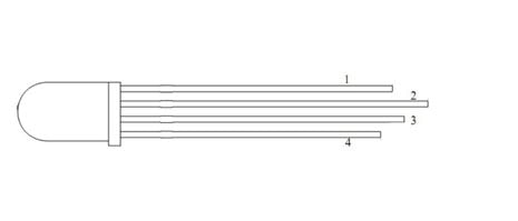
In this project we are going to interface RGB (Red Green Blue) LED with Arduino Uno. A typical RGB LED is shown in below figure:

The RGB LED will have four pins as shown in figure.
- PIN1: Color 1 negative terminal in common anode or color 1 positive terminal in common cathode
- PIN2: Common positive for all three colors in Common anode type or common negative for all three colors in common cathode type RGB LED.
- PIN3: Color 2 negative terminal or color 2 positive terminal
- PIN4: Color 3 negative terminal or color 3 positive terminal
So there are two types of RGB LEDs, one is common cathode type (common negative) and other is common anode type (common positive) type. In CC (Common Cathode or Common Negative), there will be three positive terminals each terminal representing a color and one negative terminal representing all three colors. The internal circuit of a CC RGB LED can be represented as below.

In Common Cathode type, If we want RED to be On in above, we need to power the RED LED pin and ground the common negative. The same goes for all the LEDs. In CA (Common Anode or Common Positive), there will be three negative terminals each terminal representing a color and one positive terminal representing all three colors.
The internal circuit of a CA RGB LED can be represented as shown in figure.

In Common Anode type, if we want RED to be on in above, we need to ground the RED LED pin and power the common positive. The same goes for all the LEDs.
In our circuit we are going to use CA (Common Anode or Common Positive) type. If you want to connect more RGB LEDs, say 5, then you need 5x4= 20 PINS usually, but we can reduce this PIN usage to 8 by connecting RGB LEDs in parallel and by using a technique called multiplexing.
Required Components:
- Arduino Uno
- RGB LED (Common Anode)
- Resistor – 1k
Circuit and Working Explanation
The circuit connection for RGB LED Arduino interfacing is shown in below figure.

Here we have connected Common Anode terminal of RGB LED with the 5v supply of Arduino along with a 1k Resistor.
Now Negative pins (1, 3, 4) of RGB LED is connected to Arduino Pin 2, 3 and 4. Here RGB LED is connected in reverse logic means if we make ground terminal of LED high, it will turn off. So here we are making ground terminal of RGB LED high to keep the respective LED in off state. And if we make ground terminal of RGB LED low it will glow.
So as we have already seen in above pin diagram of RGB LED that pin 2 is common anode, and pin 1, 3 and 4 are the ground terminals of Red, blue and green color respectively.
In below code, you can check that we are alternatively blinking all three colors in RGB led by making the Ground terminals of RGB high and low. Remember that LED will be off when ground terminal of respective color is high and LED will glow when ground Terminal of Respective color is Low.
Check the complete Arduino code and Video below.
This is how we program a RGB LED with Arduino, if you want use Multiple RGB LEDs with Arduino then check this one.
Complete Project Code
void setup() {
    pinMode(2, OUTPUT);
    pinMode(3, OUTPUT);
    pinMode(4, OUTPUT);

}
void loop() {
  digitalWrite(2, LOW);
  delay(500);

  digitalWrite(2, HIGH);
  delay(500);

  digitalWrite(3, LOW);
  delay(500);

  digitalWrite(3, HIGH);
  delay(500);
  digitalWrite(4, LOW);
  delay(500);

  digitalWrite(4, HIGH);
  delay(500);
}
