
By Kartik Khandelwal
Core Purpose: NeuroBand is a specialized smart safety armband engineered to provide timely assistance to elderly and high-risk individuals during emergencies. Its primary goal is to mitigate the risks associated with falls and medical crises while simultaneously addressing the industry-wide challenge of frequent false alarms.
The Global Context of Falls:
- Global Impact: Falls are a critical public health issue. According to the World Health Organization (WHO), approximately 684,000 fatal falls occur globally each year, making it the second leading cause of unintentional injury death, after road traffic injuries [1].
- Regional Burden: The impact is disproportionately high in low- and middle-income regions. In India, research indicates that approximately one-third of older adults experience a fall at some point, highlighting the urgent need for reliable safety solutions [2].
- The Critical Factor: In many fall incidents, the severity of the outcome is often dictated not by the fall itself, but by the "long lie"—the delay in receiving medical attention. NeuroBand aims to bridge this gap by ensuring rapid response.
Addressing Current Limitations:
- The False Alarm Problem: Traditional safety wearables often rely on binary triggers, such as a simple acceleration spike or a panic button. These mechanisms frequently misinterpret daily actions—like sitting down abruptly or dropping the device—as emergencies.
- Consequences: Frequent false positives lead to "alarm fatigue," causing caregivers to distrust alerts and potentially ignore genuine emergencies.
- NeuroBand’s Solution: Unlike single-trigger devices, NeuroBand employs a contextual approach. It continuously observes multiple signal streams to cross-verify data, ensuring that an alert is only triggered when a genuine threat is detected.
Architecture
NeuroBand utilizes a cohesive system design that merges advanced hardware sensing with a robust software framework.
Hardware Sensing Layer:
- Motion Sensing: The device is equipped with high-fidelity accelerometers and gyroscopes to map user activity, posture, and sudden orientation changes.
- Heart Rate Monitoring: Continuous optical sensors track cardiovascular stability, providing a baseline for the user's normal physiological state.
- ECG Integration: The inclusion of an ECG (Electrocardiogram) sensor allows the device to capture detailed electrical heart activity, offering a deeper diagnostic view than standard pulse trackers.
- Data Fusion: By combining physical movement data with physiological responses, the hardware provides a holistic view of the user's status (e.g., distinguishing a stumble from a syncopal fall caused by a heart condition).
Software Intelligence Layer:
- Real-Time Operating System (RTOS): The device runs on an RTOS, which allows for deterministic and parallel task management. This ensures that critical safety tasks are never blocked by background processes.
- Task Prioritization: The software architecture creates a hierarchy where emergency detection and user interaction are treated as high-priority tasks, while data logging and routine monitoring run in the background.
- Signal Processing: Raw sensor data is subjected to advanced filtering and smoothing algorithms. This pre-processing step eliminates sensor noise and short-term artifacts associated with normal daily movement, preventing false triggers.
- Resource Synchronization: To maintain system stability, shared resources—such as sensor communication buses and memory buffers for ECG data—are managed via strict synchronization protocols to prevent data corruption.
System Flow and Communication
The operational logic of NeuroBand is designed to transition smoothly between monitoring, evaluation, and emergency response.
Phase 1: Continuous Monitoring (Normal Operation)
- Background Operation: The device operates unobtrusively, logging motion, heart rate, and ECG signals without user intervention.
- Pattern Evaluation: Instead of reacting to instantaneous spikes, the system analyzes trends. For example, a sudden motion spike is flagged as a "potential" fall, but the system checks subsequent data (like a period of immobility or abnormal heart rate) before confirming.
- Lightweight Communication: During this phase, the device uses a low-bandwidth messaging protocol to send periodic "heartbeat" updates (activity status, battery level) to the mobile app, ensuring the system is online without draining the battery.
Phase 2: Emergency Detection
- Trigger Conditions: The system enters a high-alert state if it detects:
- A manual SOS request from the user.
- Repeated fall-like motion signatures.
- Sustained abnormal vital signs (e.g., bradycardia or tachycardia) following a motion event.
Contextual Verification: By cross-referencing the motion event with the heart rate recovery, the device filters out non-emergencies (e.g., a user tripping but recovering immediately).
Phase 3: HELP Mode (Response)
- Immediate Alerts: Upon confirming a high-risk situation, NeuroBand activates "HELP Mode."
- Audible Alarm: A loud SOS siren is played on the device to alert anyone in the immediate vicinity.
- Remote Notification: Simultaneously, critical alerts are pushed over WiFi to the caregiver's mobile app. Crucially, this packet includes a snippet of recent ECG data recorded just prior to the event, providing medical context.
- User Control: The user retains the ability to cancel the alarm if the trigger was accidental, maintaining their agency and reducing unnecessary panic.
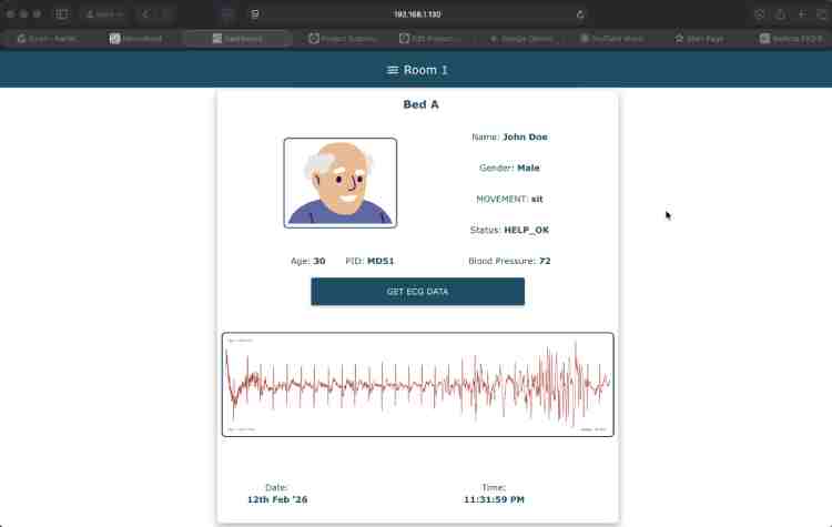
Phase 4: Caregiver Dashboard
- Live Telemetry: Caregivers access a centralized dashboard displaying live vital signs and current activity status.
- Incident Context: In the event of an alarm, the dashboard highlights the specific trigger and presents the recorded ECG data, allowing caregivers or medical professionals to assess the severity of the incident remotely before dispatching help.
References
- World Health Organization. (2021). Falls: Key Facts. Retrieved from https://www.who.int/news-room/fact-sheets/detail/falls
- Sirohi, A., et al. (2017). Epidemiology of falls and its risk factors among elders in a rural area of Coimbatore, India.International Journal of Community Medicine and Public Health. (Noting prevalence rates of falls among Indian older adults are often estimated at around 31-33%).
Components Required
| Component Name | Quantity | Datasheet/Link |
|---|---|---|
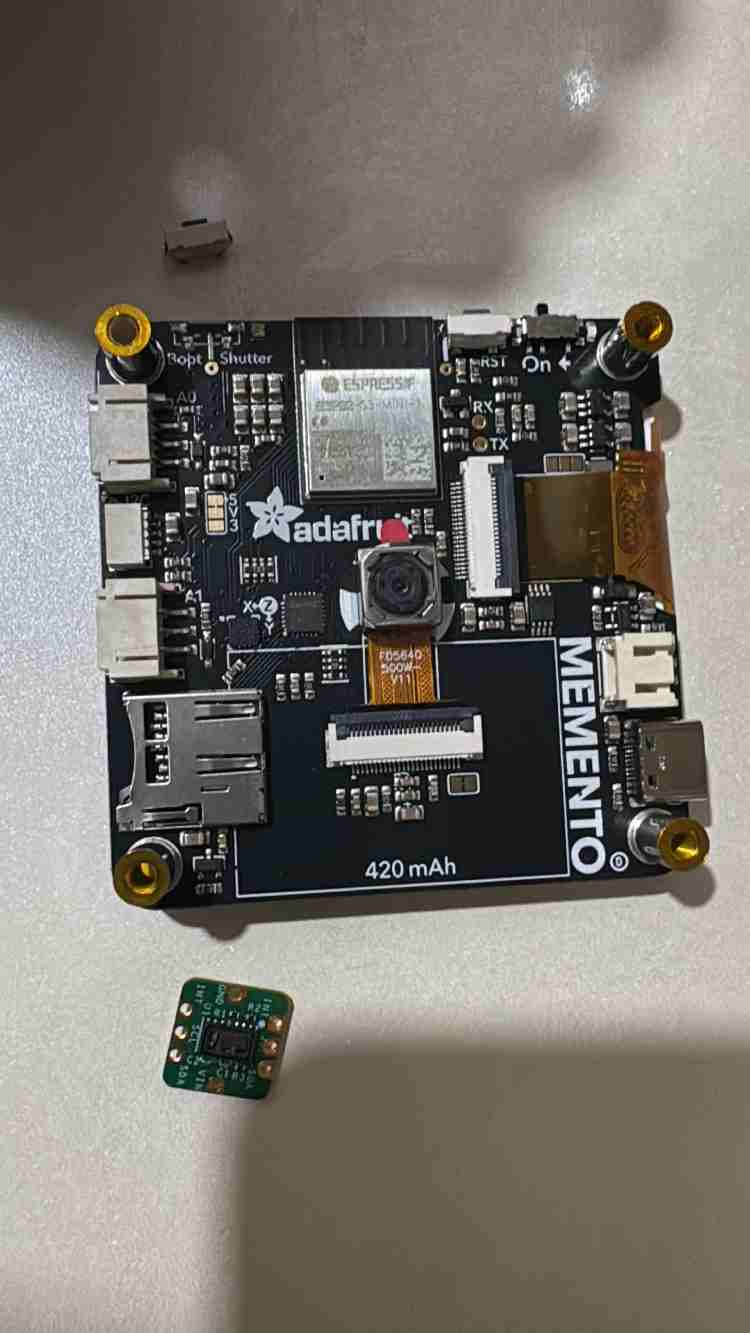
| MEMENTO Programmable Camera | 1 | View Datasheet |
| MAXREFDES117 Bio-Sensor | 1 | View Datasheet |
| Biome EXG Pill Set | 1 | View Datasheet |
| Adafruit STEMMA QT Cable | 1 | View Datasheet |
| 3 pin JST PH Cable | 1 | View Datasheet |
| Battery Bank | 1 | View Datasheet |
| Type-C Cable | 1 | View Datasheet |
| Jumper Cables (M-M, M-F) | 10 | View Datasheet |
| Zero PCB | 1 | View Datasheet |
| Digital Oximeter | 1 | View Datasheet |
| Glue Gun and stick | 1 | View Datasheet |
| Male Header Pins | 1 | View Datasheet |
| Soldering Kit | 1 | View Datasheet |
| 3D Printed Models ( 1 + 1 ) | 1 | View Datasheet |
| Spiral Cable Protector | 1 | View Datasheet |
Circuit Diagram
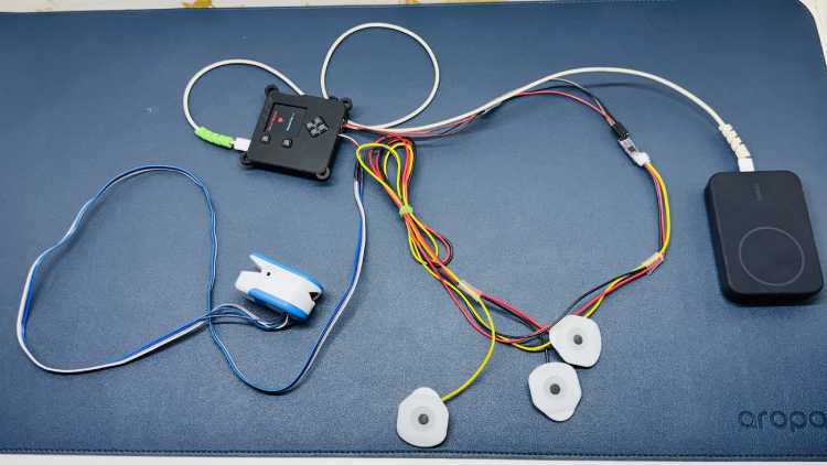
Physiological Sensing
The system utilizes two primary modalities for cardiac monitoring:
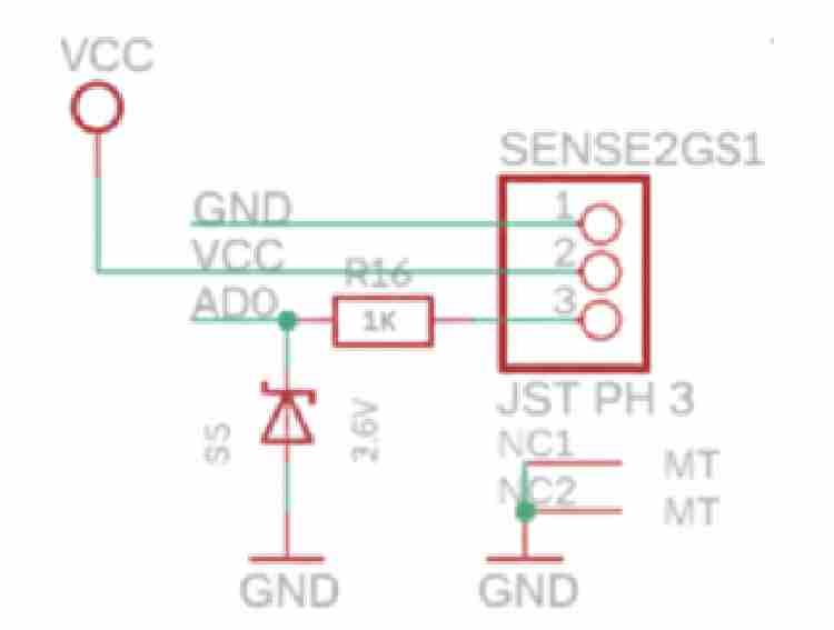
- Biopotential Acquisition: An UpsideDown Labs BioAMP-EXG Pill is interfaced via Analog Port 0 (A0) to capture raw ECG data.
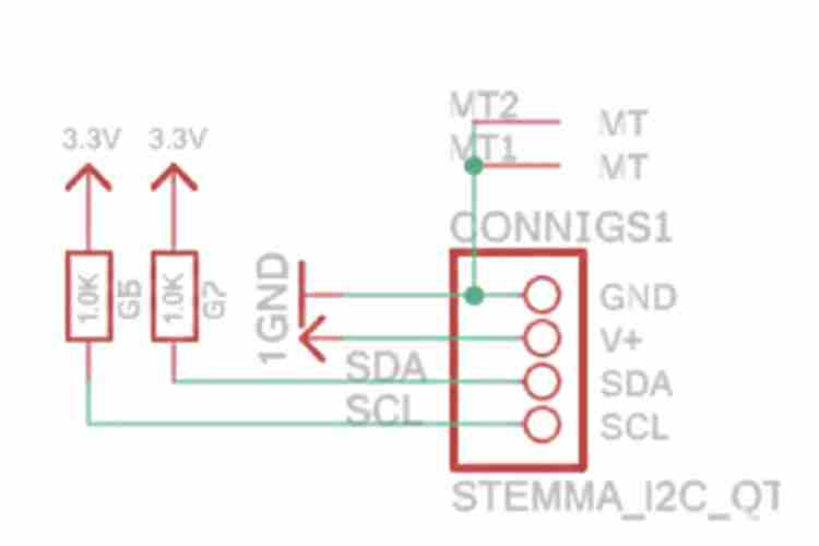
- Optical Heart Rate Monitoring: A MAXREFDES117 Bio-Sensor is connected via the I2C bus to provide heart rate measurements.
Power Management
Due to the high current demands of the system exceeding 1500mA, a standard LiPo battery was insufficient. This significant load is driven by:
- On-board Neural Network inference.
- Active Wi-Fi telemetry.
- Simultaneous operation of multiple peripherals.
- To ensure stable operation and provide sufficient current overhead, a high-capacity Battery Bank was utilized as the primary power source.
Design Documentation
The system architecture, including the full circuit schematic and component interconnects, was designed and documented using Fritzing and all the changes in existing 3D models were made using Solidworks.


Hardware Assembly
Part 1: Making the Case (3D Design)
Step 1: Creating the Design
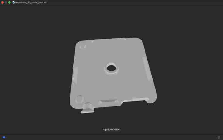
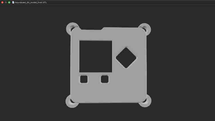
- I started with a design from Adafruit called [Design A] (see Figure 1). However, I realized it needed some changes to fit our project better:
- Better Hangers: I made the corner hangers bigger and added more so the band stays on securely (Figure 2).
- New Holes: I added specific holes (slots) for the I2C and A0 cables so everything connects easily (Figure 2).
Big thanks to my friend Utkarsh for helping with these changes!
Step 2: Printing the Parts
- I ordered the parts from Robu.in. If you are ordering yours, upload both part files and use these settings (Figure 3):
- Material: PLA - Black
- Quality: Standard (0.2 mm)
- Infill: 90%
- Unit: mm

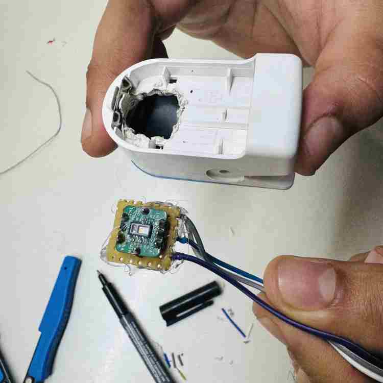
Part 2: Assembling the Heart Sensor (MAXREFDES117)
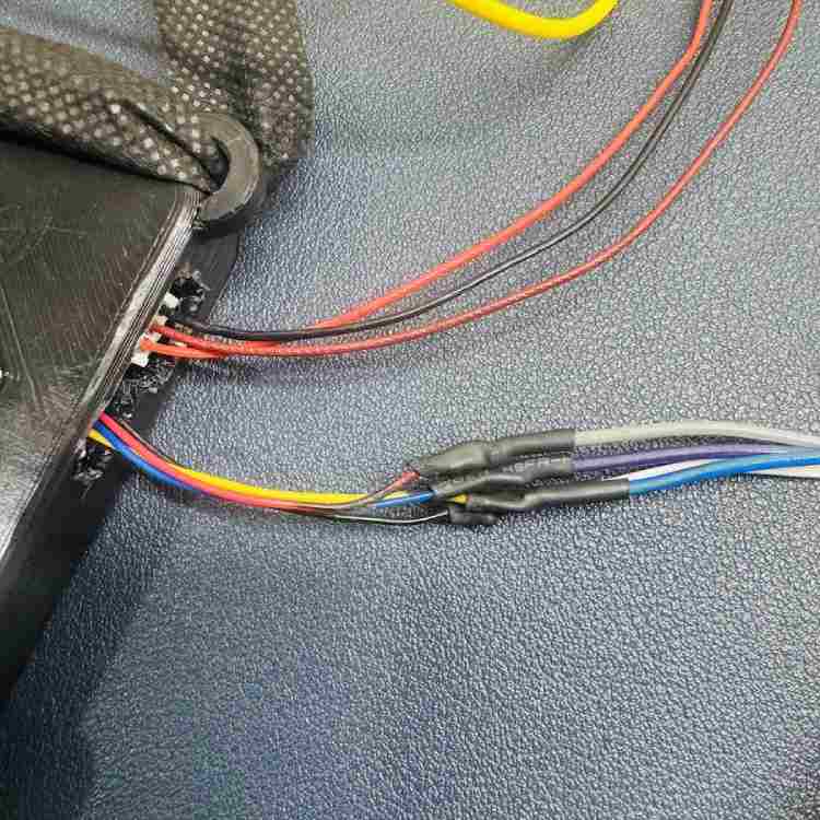
Step 1: Preparing the Wires
- The Cable: The Adafruit cable comes with plugs on both ends. Cut one plug off.
- Soldering: Strip the plastic off the cut wires and solder them to female jumper wires.
- Protection: Cover the soldered joints with heat shrink tubes so the wires don't touch each other (Figure 4).
- The Board: Cut a small piece of Zero PCB. It should be the same size as the sensor, plus two extra holes on each side. Solder pins onto this board (Figure 5).
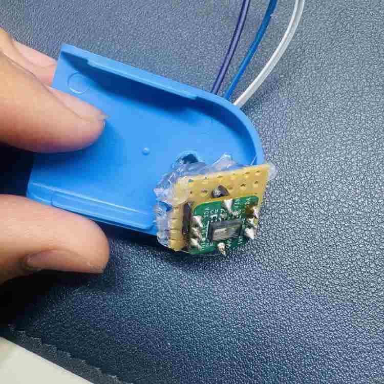
Step 2: Modifying the Case
- Cutting: Cut a hole in the plastic oximeter case. Be very careful not to cut the spring inside! (Figure 6).
- Gluing: Put the sensor inside the hole you just made. Use a glue gun to hold it tight so it doesn't move (Figure 7).

Step 3: Connecting It
- Plug the cable into the I2C port on the main board.
- Check This: Make sure the Power (VCC) and Ground (GND) wires match the diagram before turning it on (Figure 8).
Part 3: Assembling the EXG Sensor
Step 1: Preparing the Cable
- Take the 3-pin cable. Just like before, cut one end off.
- Solder the cut wires to female jumper wires and cover them with heat shrink tubes (Figure 9).
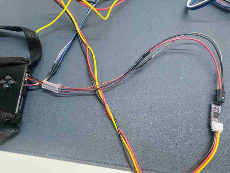
Step 2: Connecting It
- Plug the uncut end into the BioAmp EXG board.
- Plug the soldered end into the A0 port on the main board.
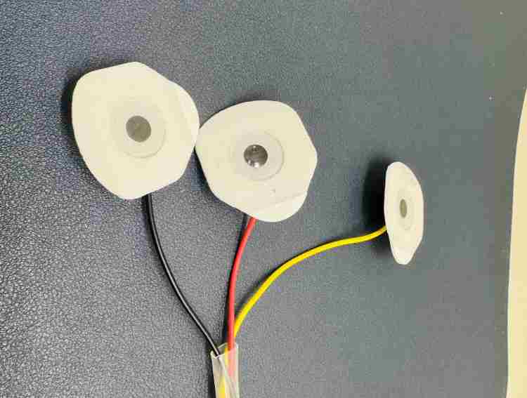
Part 4: Attaching the ECG Pads
Step 1: Connect the Cable
- Plug the long BioAmp Cable v3 into the sensor board.
Step 2: Add the Pads
- Snap the sticky gel pads onto the ends of the cable (Figure 10)
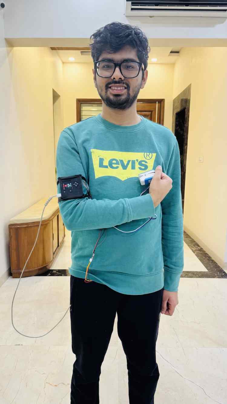
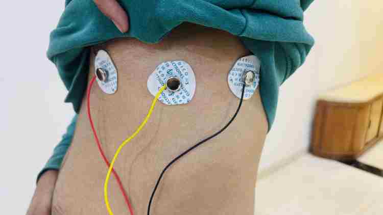
Step 3: Stick Them on Your Body
- Based on doctor recommendations, place the pads on your chest in these spots (Figure 11):
- V4: In the space between your ribs, directly down from the center of your collarbone.
- V5: In a straight line from V4, near the front of your armpit.
- V6: In a straight line from V5, directly in the middle of your armpit.
Code Explanation
NeuroBand Device Code
1. Executive Summary
Neuroband is a wearable health monitoring system designed to track vital signs (Heart Rate, ECG) and detect falls in real-time. The system utilizes an ESP32-S3 microcontroller running FreeRTOS to manage concurrent sensor acquisition, data processing, display updates, and cloud communication via MQTT.
The codebase is structured into modular components separating hardware abstraction (HAL), signal processing, and application logic. This document details the function and logic of each core file pair (.cpp and .h).
2. Software Architecture Overview
The system operates on a dual-core architecture using FreeRTOS tasks to ensure deterministic behavior for critical health monitoring.
- Core 0 (Connectivity & Sensing): Handles high-frequency analog sampling (ECG), I2C sensor polling (Oximeter), and network communication (WiFi/MQTT).
- Core 1 (Compute & UI): Dedicated to computationally intensive Edge ML inference (Fall Detection), user interface updates (OLED), and button input management.
3. Detailed Function Analysis
3.1 Main Application Entry
Files: src/main.cpp
This file serves as the orchestrator of the system. It initializes the hardware, creates FreeRTOS tasks, and defines global synchronization objects (mutexes/semaphores).
Functions
void setup()
- Purpose: Initializes the ESP32 hardware and FreeRTOS kernel.
- Logic:
- Initializes UART for debug output (115200 baud).
- Configures I2C buses (Standard and Fast modes).
- Initializes subsystems: OLED, AW9523 (IO Expander), WiFi, and Sensors.
- Creates synchronization primitives: i2cMutex (protects I2C bus), ecgBufferMutex (protects data rings), helpStateMutex.
- Task Creation: Spawns all application tasks pinned to specific cores as defined in the architecture.
- Context: Runs once on boot.
void loop()
- Purpose: Standard Arduino loop, typically unused in FreeRTOS implementations or used as a low-priority idle hook.
- Logic: Executes vTaskDelete(NULL) or yields to allow the RTOS scheduler to manage priority tasks defined in setup().
void ECG_Analog_Task(void *pvParameters)
- Purpose: High-priority task for acquiring ECG signal data.
- Logic: Runs at 125 Hz (8ms interval). Reads the analog value from the ECG pin, applies a high-pass filter to remove DC wander, and pushes the sample into the circular ECG buffer protected by ecgBufferMutex.
void Oximeter_I2C_Task(void *pvParameters)
- Purpose: Polls the MAX30105 sensor for heart rate data.
- Logic: Runs every 20ms. Acquires the i2cMutex, reads the IR/Red values, and computes BPM. It implements a median filter and Exponential Moving Average (EMA) to smooth the BPM output before updating the global state.
void Accelerometer_Task(void *pvParameters)
- Purpose: Feeds motion data into the Edge ML classifier.
- Logic: Polls the LIS3DH accelerometer at 50 Hz. Buffers data and runs the fall_detection inference engine. If a fall is detected (class index match), it increments a fall counter. Triggers an SOS if the CONSECUTIVE_FALL_THRESHOLD is met.
void MQTT_Send_Task(void *pvParameters)
- Purpose: Publishes telemetry to the cloud.
- Logic: Runs every 1 second. Formats a JSON payload containing BPM, Fall Status, and SOS state. Publishes to the configured MQTT topic. Handles automatic reconnection if WiFi drops.
void SOS_Task(void *pvParameters)
- Purpose: Manages the emergency alert outputs.
- Logic: Blocked on a semaphore until triggered by Fall Detection or Button Press. When active, it drives the speaker (via AW9523 or PWM) in a specific SOS pattern and forces the display to an alert screen.
3.2 IO Expansion & Control
Files: src/aw9523.cpp, include/aw9523.h
This module interfaces with the AW9523 GPIO expander, used to expand the limited pins of the ESP32-S3 for button inputs and LED/Speaker control.
Functions
AW9523::AW9523(uint8_t addr)
- Purpose: Constructor.
- Parameters: addr - The I2C address of the expander (default 0x58).
- Logic: Stores the address for future bus transactions.
bool AW9523::begin(TwoWire *wire)
- Purpose: Initializes the driver.
- Parameters: wire - Pointer to the I2C bus instance.
- Logic:
- Resets the chip via software reset (if supported) or power cycle delay.
- Verifies chip ID to ensure hardware presence.
- Configures default port directions (Input for buttons, Output for Speaker/LEDs).
Return: true if chip detected, false otherwise.
void AW9523::pinMode(uint8_t pin, uint8_t mode)
- Purpose: Sets the direction of a specific virtual pin.
- Logic: Writes to the configuration register (Port 0 or Port 1) to set the bit corresponding to pin as input or output.
void AW9523::digitalWrite(uint8_t pin, uint8_t val)
- Purpose: Sets the state of an output pin.
- Logic: Calculates the register offset (Output Port 0 vs 1) and bitmask. Sends an I2C write command to update the specific bit without affecting others.
uint8_t AW9523::digitalRead(uint8_t pin)
- Purpose: Reads the state of an input pin.
- Logic: Reads the Input Port register via I2C. Masks the result to return the boolean state of the requested pin.
3.3 ECG Signal Processing
Files: src/ecg.cpp, include/ecg.h
This module handles the raw analog interfacing and signal conditioning for the ECG sensor.
Functions
void ECG_Init()
- Purpose: Configures the ADC and Lead-Off detection pins.
- Logic: Sets LO+ and LO- pins as inputs to detect if the pads are disconnected. Configures the ADC resolution (12-bit) and attenuation.
int16_t ECG_ReadRaw()
- Purpose: Captures a single raw sample.
- Logic: Checks Lead-Off pins first. If leads are off, returns a specific error code or flatline value. Otherwise, performs analogRead() on the sensor pin.
float ECG_Filter(int16_t rawValue)
- Purpose: Cleans the signal for visualization or processing.
- Logic: Implements a digital Infinite Impulse Response (IIR) high-pass filter to remove baseline wander (breathing artifacts) and potentially a notch filter (50/60Hz) to remove power line noise.
bool ECG_GetLeadsOff()
- Purpose: Safety check for electrode connection.
- Logic: Reads the digital state of the LO+ and LO- pins. Returns true if either is High (indicating a disconnect).
3.4 Fall Detection (Edge AI)
Files: src/fall_detection.cpp, include/fall_detection.h
This file wraps the Edge Impulse SDK to provide high-level inference capabilities.
Functions
void FallDetection_Init()
Purpose: Allocates memory for the neural network model.
Logic: Calls run_classifier_init() from the Edge Impulse SDK. Verifies that the model fits in RAM and that the DSP blocks are initialized.
int FallDetection_RunInference(float *accelData, size_t length)
Purpose: Classification of movement data.
Parameters: accelData - An array of (x, y, z) tuples representing the time window (e.g., 2-3 seconds).
Logic:
- Converts the raw accelerometer array into the signal format required by the SDK.
- Calls run_classifier().
- Parses the result vector (Probability for "Idle", "Walking", "Fall").
Return: The index of the class with the highest confidence score.
bool FallDetection_IsFallDetected(int classIndex)
- Purpose: Helper to interpret the result.
- Logic: Compares classIndex against the known ID for the "Fall" label. Returns true if it matches and confidence > 0.8.
3.5 Display Management
Files: src/oled.cpp, include/oled.h
Manages the visual feedback on the OLED screen, drawing vital signs, status icons, and emergency alerts.
Functions
void OLED_Init()
- Purpose: Starts the display driver.
- Logic: Initializes the SPI interface and the SSD1306/ST7735 controller. Clears the screen and sets the default font size and rotation.
void OLED_UpdateStatus(int bpm, bool wifiConnected, bool mqttConnected)
- Purpose: Routine UI update.
- Logic:
- Draws the "Top Bar" with WiFi/MQTT icons (filled or crossed out based on booleans).
- Clears the BPM area to prevent ghosting.
- Prints the bpm value in large font.
- Draws a dynamic heart icon (toggles size to simulate beating).
void OLED_ShowSOS()
- Purpose: Emergency override screen.
- Logic: Inverts the display colors (white background, black text) for maximum visibility. Displays "SOS" and "HELP" in the largest available font.
void OLED_DrawGraph(float value)
- Purpose: Real-time plotting of ECG/Pulse.
- Logic: Shifts the internal pixel buffer to the left by 1 pixel. Plots the new value mapped to the screen height at the rightmost column.
3.6 Pulse Oximetry
Files: src/oximeter.cpp, include/oximeter.h
Driver interface for the Maxim Integrated MAX30105/MAX30102 sensor.
Functions
bool Oximeter_Init()
- Purpose: Configures the sensor.
- Logic: Sets LED pulse amplitude, sample rate (usually 100Hz or 400Hz), and pulse width. Initializes the particle sensing mode.
void Oximeter_Update()
- Purpose: State machine for beat detection.
- Logic:
- Reads the FIFO buffer from the sensor.
- Passes the IR signal to the beat detector algorithm (checkForBeat()).
- If a beat is found, calculates the time delta since the last beat to derive instantaneous BPM.
- Updates the moving average to filter out noise.
int32_t Oximeter_GetHeartRate()
- Purpose: Getter for other modules.
- Return: The current smoothed BPM value.
3.7 Connectivity
Files: src/wifi_helper.cpp, include/wifi_helper.h
Wraps the standard Arduino WiFi and MQTT libraries to provide robust connection handling.
Functions
void WiFi_Connect(const char* ssid, const char* pass)
- Purpose: Establishes network link.
- Logic: Sets WiFi mode to STATION. Calls WiFi.begin(). Enters a blocking loop (or task delay loop) blinking an LED until WiFi.status() == WL_CONNECTED.
void MQTT_Reconnect()
- Purpose: Ensures cloud link is active.
- Logic: Checks client.connected(). If false, generates a random Client ID (to avoid broker conflicts) and attempts connection. Resubscribes to control topics (e.g., remote SOS trigger) upon success.
4. Helper Utilities
Files: src/uart.cpp, include/uart.h
void UART_Log(const char* format, ...)
- Purpose: Thread-safe logging.
- Logic: Uses a mutex to prevent interleaved serial output from multiple tasks. Formats the string (printf style) and sends it to Serial.
5. System Interdependency & Data Flow
- Sensor Input: The Oximeter_I2C_Task and ECG_Analog_Task collect raw data on Core 0.
- Shared Memory: Data is written to global variables/buffers protected by i2cMutex and ecgBufferMutex.
- Processing:
- Accelerometer_Task (Core 1) reads motion data and runs inference.
- Help_Monitor_Task checks if BPM < Threshold OR Fall_Counter > 5.
- Decision: If a threshold is crossed, the sosState flag is raised.
- Output:
- SOS_Task sees the flag and activates the Speaker/OLED.
- MQTT_Send_Task sees the flag and sends an "Emergency" JSON packet to the backend.
6. Conclusion
The Neuroband codebase demonstrates a robust implementation of a safety critical wearable. By isolating data acquisition from heavy processing via dual-core separation, it ensures that heart monitoring is not interrupted by the heavy math of fall detection or network latency.
Neuroband App Code
1. Executive Summary
The NeuroBand iOS Application serves as a visual dashboard for the NeuroBand wearable system. It is designed as a "thin client" wrapper that embeds a web interface (Node-RED Dashboard) into a native iOS application context. This allows users to monitor real-time vital signs (ECG, Heart Rate) and alerts directly on their iPhone without navigating through a browser. The application is built using SwiftUI for the lifecycle and UI layout, and utilizes WebKit to render the heavy data visualizations provided by the backend.
2. System Architecture
The app follows a View-Model pattern where the "Model" is effectively the remote Node-RED server.
- Native Layer (Swift): Handles application lifecycle, window management, and the container for the web content.
- Web Layer (HTML/JS via WebKit): Renders the graphs, gauges, and status indicators transmitted by the ESP32 via MQTT to the Node-RED server.
Communication Flow
[ESP32] --(MQTT)--> [Node-RED] --(HTTP/WebSocket)--> [iOS App (WKWebView)]
3. Detailed File Analysis
3.1 Application Entry Point
File: NeuroBandApp/NeuroBandAppApp.swift
This file is the standard entry point for a SwiftUI application. It defines the App protocol implementation which manages the app's lifecycle events (launch, backgrounding, termination).
- Struct: NeuroBandAppApp
- Purpose: Initializes the application window.
- Key Logic:
- @main Attribute: Marks this struct as the entry point for execution.
- WindowGroup: A scene container that manages the hierarchy of views. It instantiates ContentView() as the root view of the application.
- Current State: In the provided version, the functional code block is currently commented out, likely for debugging or during a transition between UIKit (AppDelegate) and SwiftUI lifecycles.
3.2 Main User Interface
File: NeuroBandApp/ContentView.swift
This file contains the UI definition and the bridge between SwiftUI and the underlying WebKit engine.
Component: extension Color
- Purpose: Defines the application's visual theme.
- Definition: themeBlueDarker
- Value: Custom RGB (0, 76, 100) matching the NeuroBand branding.
Component: struct WebView
- Type: UIViewRepresentable
- Purpose: Acts as a wrapper to expose UIKit's WKWebView to the SwiftUI declarative hierarchy.
- Function: makeUIView(context: Context) -> WKWebView
- Logic:
- Instantiates a WKWebView object.
- Creates a URLRequest targeting the Node-RED Dashboard URL (Hardcoded: http://192.168.1.130:1880/ui/).
- Calls webview.load(request) to begin fetching the dashboard.
- Returns the view instance to SwiftUI.
Function: updateUIView(_:context:)
- Logic: Empty implementation. No dynamic updates from SwiftUI to the Web Page are required for this iteration.
Component: struct ContentView
- Type: View
- Purpose: The primary screen layout.
- Logic:
- Wraps the WebView() component inside the body.
- Applying ignoresSafeArea() ensures the dashboard stretches edge-to-edge, utilizing the full notch/dynamic island area for an immersive experience.
4. Configuration & Setup
Hardcoded Configuration
The application currently targets a static IP address for the backend server:
Recommendation for Deployment: For a production environment, this should be refactored to:
- Use mDNS/Bonjour (e.g., http://neuroband.local:1880/ui/) to automatically discover the server without hardcoded IPs.
- Implement a Settings Bundle allowing the user to input their specific broker IP address.
5. Deployment Requirements
- Minimum iOS Version: iOS 14.0 (Required for App protocol and WindowGroup).
- Network: The iOS device must be on the same Local Area Network (WiFi) as the Node-RED server, or the server must be exposed via Port Forwarding/VPN.
- Permissions: The Info.plist must include NSAppTransportSecurity exceptions to allow insecure HTTP loads (http://) since the local Node-RED instance typically lacks SSL/TLS encryption.
GitHub Repository


Complete Project Code
#include <Arduino.h>
#include <WiFi.h>
#include <Wire.h>
#include <PubSubClient.h>
#include <Adafruit_LIS3DH.h>
#include <Adafruit_Sensor.h>
#include <MAX30105.h>
#include "fall_detection.h"
#include "uart.h"
#include "oled.h"
#include "oximeter.h"
#include "ecg.h"
#include "wifi_helper.h"
#include "aw9523.h"
// ==================== WiFi & MQTT Configuration ====================
const char* ssid = "TP-Link_6391";
const char* password = "AKMR@159";
const char* mqtt_server = "192.168.1.130";  // Your MQTT broker IP
// MQTT Topics
const char* TOPIC_MOVEMENT_STATUS = "esp32/movement_status";
const char* TOPIC_BLOOD_PRESSURE = "esp32/blood_pressure_value";
const char* TOPIC_ASK_ECG = "esp32/ask_ecg_data";
const char* TOPIC_RECEIVE_ECG = "esp32/recieve_ecg_data";
const char* TOPIC_HELP_STATUS = "esp32/help_status";
WiFiClient espClient;
PubSubClient mqttClient(espClient);
// ==================== AW9523 Button & Speaker Pin Definitions ====================
// CONFIRMED button mappings from hardware testing:
// Port0: SELECT = bit 1 (P0_1)
// Port1: UP=bit5, DOWN=bit7, LEFT=bit6, RIGHT=bit4, OK=bit3
#define AW9523_PIN_SPEAKER_EN   0   // P0_0 - Speaker enable
#define AW9523_PIN_BTN_UP       13  // P1_5 (bit 5 of Port1)
#define AW9523_PIN_BTN_DOWN     15  // P1_7 (bit 7 of Port1)
#define AW9523_PIN_BTN_LEFT     14  // P1_6 (bit 6 of Port1)
#define AW9523_PIN_BTN_RIGHT    12  // P1_4 (bit 4 of Port1)
#define AW9523_PIN_BTN_SELECT   1   // P0_1 (bit 1 of Port0)
#define AW9523_PIN_BTN_OK       11  // P1_3 (bit 3 of Port1)
#define OK_BUTTON_PIN           11  // ESP32 GPIO for OK button (stops SOS)
#define SPEAKER_PIN             46  // ESP32 GPIO for speaker PWM
// Speaker PWM settings
const int PWM_CHANNEL = 0;
const int PWM_RES = 8;
const int TONE_FREQ = 1000;
// SOS timing (in ms)
const int DOT_DURATION = 150;
const int DASH_DURATION = 450;
const int SYMBOL_GAP = 150;
const int LETTER_GAP = 450;
AW9523 gpioExpander(AW9523_DEFAULT_ADDR);
bool aw9523Available = false;
// ==================== ECG Circular Buffer ====================
// 20 seconds of data at 125 Hz = 2500 samples
#define ECG_BUFFER_SIZE 2500
float ecgBuffer[ECG_BUFFER_SIZE];
volatile int ecgBufferHead = 0;
volatile int ecgBufferCount = 0;
volatile bool ecgDataRequested = false;
SemaphoreHandle_t ecgBufferMutex;
// ==================== Help Detection State ====================
// Thresholds and timing
#define LOW_BPM_THRESHOLD 60
#define LOW_BPM_DURATION_MS 20000  // 20 seconds
#define CONSECUTIVE_FALL_THRESHOLD 5
// State variables (protected by helpStateMutex)
volatile bool helpActive = false;
volatile bool sosPlaying = false;
volatile unsigned long lowBpmStartTime = 0;
volatile bool lowBpmConditionMet = false;
volatile int consecutiveFallCount = 0;
volatile bool okButtonPressed = false;
// Synchronization primitives
SemaphoreHandle_t helpStateMutex;         // Mutex for help state variables
SemaphoreHandle_t sosStopSemaphore;       // Binary semaphore to stop SOS
SemaphoreHandle_t i2cMutex;               // Mutex for I2C bus access
// FreeRTOS Software Timers
TimerHandle_t lowBpmTimer;                // 20-second one-shot timer for low BPM condition
TimerHandle_t mqttReconnectTimer;         // 5-second periodic timer for MQTT reconnection
TimerHandle_t fallResetTimer;             // Timer to reset fall counter after inactivity
#define I2C_SDA 34
#define I2C_SCL 33
Adafruit_LIS3DH lis = Adafruit_LIS3DH();
MAX30105 particleSensor;
FallDetection fallDetector(&lis);
Oximeter oximeter(&particleSensor);
ECG ecg;
UART uart;
OLED oled;
WiFiHelper wifi(ssid, password);
volatile float g_beatsPerMinute = 0.0;
volatile int g_beatAvg = 0;
volatile float g_ecgFiltered = 0.0;
TaskHandle_t ECG_Task_Handle;
TaskHandle_t Oximeter_Task_Handle;
TaskHandle_t Accelerometer_Task_Handle;
TaskHandle_t Display_Task_Handle;
TaskHandle_t UART_Debug_Task_Handle;
TaskHandle_t MQTT_Send_Task_Handle;
TaskHandle_t MQTT_ECG_Task_Handle;
TaskHandle_t Button_Task_Handle;
TaskHandle_t SOS_Task_Handle;
TaskHandle_t Help_Monitor_Task_Handle;
void ECG_Analog_Task(void *pvParameters);
void Oximeter_I2C_Task(void *pvParameters);
void Accelerometer_Task(void *pvParameters);
void Display_Task(void *pvParameters);
void UART_Debug_Task(void *pvParameters);
void Send_To_NodeRed_Task(void *pvParameters);
void Receive_And_Send_ECG_Task(void *pvParameters);
void Button_Task(void *pvParameters);
void SOS_Task(void *pvParameters);
void Help_Monitor_Task(void *pvParameters);
void initSensors();
void initDisplay();
void initMQTT();
void initButtons();
void initSpeaker();
void mqttCallback(char* topic, byte* payload, unsigned int length);
void pushECGSample(float value);
String getECGBufferAsString();
void triggerHelp(const char* reason);
void stopHelp();
bool checkHelpButton();
void playSOS();
// Timer callback declarations
void lowBpmTimerCallback(TimerHandle_t xTimer);
void mqttReconnectTimerCallback(TimerHandle_t xTimer);
void fallResetTimerCallback(TimerHandle_t xTimer);
void setup() {
 uart.begin(115200);
 delay(1000);
 uart.printHeader("Neuroband ESP32-S3 FreeRTOS Project");
 Wire.begin(I2C_SDA, I2C_SCL);
 // Create synchronization primitives
 ecgBufferMutex = xSemaphoreCreateMutex();
 helpStateMutex = xSemaphoreCreateMutex();
 sosStopSemaphore = xSemaphoreCreateBinary();
 i2cMutex = xSemaphoreCreateMutex();

 // Create software timers
 lowBpmTimer = xTimerCreate(
   "LowBpmTimer",
   pdMS_TO_TICKS(LOW_BPM_DURATION_MS),  // 20 seconds
   pdFALSE,                              // One-shot
   NULL,
   lowBpmTimerCallback
 );

 mqttReconnectTimer = xTimerCreate(
   "MqttReconnect",
   pdMS_TO_TICKS(5000),                  // 5 seconds
   pdTRUE,                               // Auto-reload (periodic)
   NULL,
   mqttReconnectTimerCallback
 );

 fallResetTimer = xTimerCreate(
   "FallReset",
   pdMS_TO_TICKS(3000),                  // 3 seconds to reset fall counter
   pdFALSE,                              // One-shot
   NULL,
   fallResetTimerCallback
 );

 // Initialize ECG buffer with zeros
 memset(ecgBuffer, 0, sizeof(ecgBuffer));
 initDisplay();
 initButtons();
 initSpeaker();
 wifi.begin();
 initMQTT();
 initSensors();
 xTaskCreatePinnedToCore(
   ECG_Analog_Task,
   "ECG_Analog",
   4096,
   NULL,
   2,
   &ECG_Task_Handle,
   0
 );
 xTaskCreatePinnedToCore(
   Oximeter_I2C_Task,
   "Oximeter_I2C",
   4096,
   NULL,
   2,
   &Oximeter_Task_Handle,
   0
 );
 xTaskCreatePinnedToCore(
   Accelerometer_Task,
   "Accelerometer",
   8192,  // Increased stack for Fall Detecton
   NULL,
   1,
   &Accelerometer_Task_Handle,
   1
 );
 xTaskCreatePinnedToCore(
   Display_Task,
   "Display",
   4096,
   NULL,
   1,
   &Display_Task_Handle,
   0
 );
 xTaskCreatePinnedToCore(
   UART_Debug_Task,
   "UART_Debug",
   4096,
   NULL,
   1,
   &UART_Debug_Task_Handle,
   0
 );
 xTaskCreatePinnedToCore(
   Send_To_NodeRed_Task,
   "MQTT_Send",
   4096,
   NULL,
   1,
   &MQTT_Send_Task_Handle,
   0
 );
 xTaskCreatePinnedToCore(
   Receive_And_Send_ECG_Task,
   "MQTT_ECG",
   8192,  // Larger stack for ECG string building
   NULL,
   1,
   &MQTT_ECG_Task_Handle,
   0
 );
 xTaskCreatePinnedToCore(
   Button_Task,
   "Button",
   4096,
   NULL,
   2,  // Higher priority for responsive button handling
   &Button_Task_Handle,
   1
 );
 xTaskCreatePinnedToCore(
   SOS_Task,
   "SOS",
   4096,
   NULL,
   1,
   &SOS_Task_Handle,
   1
 );
 xTaskCreatePinnedToCore(
   Help_Monitor_Task,
   "HelpMonitor",
   4096,
   NULL,
   1,
   &Help_Monitor_Task_Handle,
   0
 );
 Serial.println("All FreeRTOS tasks created successfully");
 Serial.println("Task scheduling started...");
}
void loop() {
 // Keep MQTT connection alive
 if (mqttClient.connected()) {
   mqttClient.loop();
 }

 // Yield to other tasks and prevent watchdog issues
 vTaskDelay(pdMS_TO_TICKS(50));
}
// ==================== MQTT Functions ====================
void mqttCallback(char* topic, byte* payload, unsigned int length) {
 Serial.print("MQTT received [");
 Serial.print(topic);
 Serial.print("]: ");

 // Convert payload to string
 char message[length + 1];
 memcpy(message, payload, length);
 message[length] = '\0';
 Serial.println(message);

 // Check if it's the ECG data request
 if (strcmp(topic, TOPIC_ASK_ECG) == 0) {
   if (message[0] == '1') {
     Serial.println("ECG data requested!");
     ecgDataRequested = true;
   }
 }
}
void initMQTT() {
 mqttClient.setServer(mqtt_server, 1883);
 mqttClient.setCallback(mqttCallback);
 mqttClient.setBufferSize(25000);  // Large buffer for ECG data (2500 samples * ~8 chars + commas)
 Serial.println("MQTT initialized");
}
void reconnectMQTT() {
 if (!mqttClient.connected() && WiFi.status() == WL_CONNECTED) {
   Serial.print("Attempting MQTT connection...");
   if (mqttClient.connect("NeurobandESP32")) {
     Serial.println("connected");
     // Subscribe to ECG request topic
     mqttClient.subscribe(TOPIC_ASK_ECG);
     Serial.println("Subscribed to: esp32/ask_ecg_data");
   } else {
     Serial.print("failed, rc=");
     Serial.println(mqttClient.state());
   }
 }
}
// ==================== ECG Buffer Functions ====================
void pushECGSample(float value) {
 if (xSemaphoreTake(ecgBufferMutex, portMAX_DELAY) == pdTRUE) {
   ecgBuffer[ecgBufferHead] = value;
   ecgBufferHead = (ecgBufferHead + 1) % ECG_BUFFER_SIZE;
   if (ecgBufferCount < ECG_BUFFER_SIZE) {
     ecgBufferCount++;
   }
   xSemaphoreGive(ecgBufferMutex);
 }
}
String getECGBufferAsString() {
 String result = "";

 if (xSemaphoreTake(ecgBufferMutex, portMAX_DELAY) == pdTRUE) {
   int count = ecgBufferCount;
   int startIdx = (ecgBufferHead - count + ECG_BUFFER_SIZE) % ECG_BUFFER_SIZE;

   for (int i = 0; i < count; i++) {
     int idx = (startIdx + i) % ECG_BUFFER_SIZE;
     if (i > 0) {
       result += ",";
     }
     result += String(ecgBuffer[idx], 4);  // 4 decimal places
   }
   xSemaphoreGive(ecgBufferMutex);
 }

 return result;
}
// ==================== Timer Callbacks ====================
void lowBpmTimerCallback(TimerHandle_t xTimer) {
 // Timer fired - 20 seconds of low BPM has passed
 if (xSemaphoreTake(helpStateMutex, pdMS_TO_TICKS(100)) == pdTRUE) {
   if (!lowBpmConditionMet) {
     lowBpmConditionMet = true;
     Serial.println("[Timer] Low BPM condition met - waiting for button press");
   }
   xSemaphoreGive(helpStateMutex);
 }
}
void mqttReconnectTimerCallback(TimerHandle_t xTimer) {
 // Attempt MQTT reconnection if disconnected
 if (!mqttClient.connected() && WiFi.status() == WL_CONNECTED) {
   Serial.println("[Timer] Attempting MQTT reconnection...");
   reconnectMQTT();
 }
}
void fallResetTimerCallback(TimerHandle_t xTimer) {
 // Reset fall counter after timeout
 if (xSemaphoreTake(helpStateMutex, pdMS_TO_TICKS(100)) == pdTRUE) {
   if (consecutiveFallCount > 0) {
     Serial.printf("[Timer] Fall counter reset (was %d)\n", consecutiveFallCount);
     consecutiveFallCount = 0;
   }
   xSemaphoreGive(helpStateMutex);
 }
}

void initSensors() {
 Serial.println("\nInitializing sensors...");
 if (!lis.begin(0x19)) {
   Serial.println("ERROR: LIS3DH accelerometer not found!");
   Serial.println("Check wiring and I2C address");
 } else {
   Serial.println("LIS3DH accelerometer initialized");
   lis.setRange(LIS3DH_RANGE_4_G);
   lis.setDataRate(LIS3DH_DATARATE_50_HZ);
 }
 if (!particleSensor.begin(Wire, I2C_SPEED_FAST)) {
   Serial.println("ERROR: MAX30105 sensor not found!");
   Serial.println("Check wiring and I2C connection");
 } else {
   Serial.println("MAX30105 sensor initialized");
   oximeter.begin();
 }
 ecg.begin();
 Serial.println("All sensors initialized\n");

 // Initialize fall detection
 fallDetector.begin();
}
void initDisplay()
{
 oled.begin();
 oled.showInitScreen("Neuroband");
}
void ECG_Analog_Task(void *pvParameters) {
 Serial.println("ECG_Analog Task started on Core 0 (125 Hz sampling)");
 while(1) {
   // update() returns true when a new sample is ready (at 125 Hz)
   if (ecg.update()) {
     g_ecgFiltered = ecg.getFilteredValue();

     // Push to circular buffer for MQTT transmission
     pushECGSample(g_ecgFiltered);
   }

   // Small delay to prevent watchdog issues, actual timing controlled by ECG class
   vTaskDelay(pdMS_TO_TICKS(1));
 }
}
void Oximeter_I2C_Task(void *pvParameters) {
 Serial.println("Oximeter_I2C Task started on Core 0");
 const TickType_t xDelay = pdMS_TO_TICKS(20);
 while(1) {
   // Protect I2C access
   if (xSemaphoreTake(i2cMutex, pdMS_TO_TICKS(100)) == pdTRUE) {
     oximeter.update();
     xSemaphoreGive(i2cMutex);
   }

   g_beatsPerMinute = oximeter.getBPM();
   g_beatAvg = oximeter.getAvgBPM();

   // Trigger heart animation on beat detection
   if (oximeter.wasBeatDetected()) {
     oled.triggerHeartBeat();
   }
   vTaskDelay(xDelay);
 }
}
void Display_Task(void *pvParameters)
{
 const TickType_t delayTicks = pdMS_TO_TICKS(100);  // Check every 100ms

 // Debounce state for finger detection
 static bool displayFingerDetected = false;
 static unsigned long lastFingerTime = 0;
 static unsigned long noFingerStartTime = 0;
 const unsigned long NO_FINGER_DELAY_MS = 500;  // Wait 500ms before showing "no finger"

 while (1) {
   long irValue = oximeter.getIR();
   bool currentFingerDetected = (irValue > 50000);

   if (currentFingerDetected) {
     // Finger detected - update immediately
     displayFingerDetected = true;
     lastFingerTime = millis();
     noFingerStartTime = 0;
   } else {
     // No finger - only update display after delay
     if (displayFingerDetected) {
       // Was showing finger, start timeout
       if (noFingerStartTime == 0) {
         noFingerStartTime = millis();
       } else if ((millis() - noFingerStartTime) >= NO_FINGER_DELAY_MS) {
         // Timeout expired, now show "no finger"
         displayFingerDetected = false;
       }
       // Keep showing last reading while waiting
     }
   }

   oled.updateStatus(g_beatsPerMinute, g_beatAvg, irValue, displayFingerDetected);
   vTaskDelay(delayTicks);
 }
}
void UART_Debug_Task(void *pvParameters)
{
 const TickType_t delayTicks = pdMS_TO_TICKS(1000);
 while (1) {
   uart.printTelemetry(g_beatsPerMinute, g_beatAvg);
   vTaskDelay(delayTicks);
 }
}
void Accelerometer_Task(void *pvParameters) {
 Serial.println("Accelerometer Task started on Core 1");
 while(1) {
   // Protect I2C access
   if (xSemaphoreTake(i2cMutex, pdMS_TO_TICKS(100)) == pdTRUE) {
     if (fallDetector.update()) {
       fallDetector.runInference();
     }
     xSemaphoreGive(i2cMutex);
   }

   vTaskDelay(pdMS_TO_TICKS(10));
 }
}
// ==================== MQTT Tasks ====================
void Send_To_NodeRed_Task(void *pvParameters) {
 Serial.println("Send_To_NodeRed Task started");

 const TickType_t delayTicks = pdMS_TO_TICKS(1000);  // Send every 1 second

 while(1) {
   // Reconnect MQTT if needed (once per loop, not spamming)
   if (!mqttClient.connected() && WiFi.status() == WL_CONNECTED) {
     reconnectMQTT();
   }

   if (mqttClient.connected()) {
     // Publish movement status (fall detection)
     const char* movementStatus = fallDetector.getLastActivity();
     mqttClient.publish(TOPIC_MOVEMENT_STATUS, movementStatus);

     // Publish blood pressure / BPM value
     char bpmString[16];
     snprintf(bpmString, sizeof(bpmString), "%.1f", g_beatsPerMinute);
     mqttClient.publish(TOPIC_BLOOD_PRESSURE, bpmString);

     // Publish help status
     if (helpActive) {
       mqttClient.publish(TOPIC_HELP_STATUS, "HELP_ACTIVE");
     } else {
       mqttClient.publish(TOPIC_HELP_STATUS, "HELP_OK");
     }

     Serial.printf("MQTT Published - Movement: %s, BPM: %s\n", movementStatus, bpmString);
   }

   vTaskDelay(delayTicks);
 }
}
void Receive_And_Send_ECG_Task(void *pvParameters) {
 Serial.println("Receive_And_Send_ECG Task started");

 const TickType_t delayTicks = pdMS_TO_TICKS(50);  // Check every 50ms for faster response

 while(1) {
   // Check if ECG data was requested
   if (ecgDataRequested) {
     // Clear flag immediately
     ecgDataRequested = false;

     Serial.println("[ECG] Data request received, waiting for MQTT connection...");

     // Wait for MQTT connection (with timeout)
     int waitCount = 0;
     while (!mqttClient.connected() && waitCount < 50) {  // 2.5 second timeout
       vTaskDelay(pdMS_TO_TICKS(50));
       waitCount++;
     }

     if (mqttClient.connected()) {
       Serial.println("[ECG] Building ECG data string...");

       // Get ECG buffer as comma-separated string
       String ecgData = getECGBufferAsString();

       if (ecgData.length() > 0) {
         Serial.printf("[ECG] Sending %d bytes of ECG data (%d samples)\n",
                       ecgData.length(), ecgBufferCount);

         // Ensure MQTT loop is run before publishing
         mqttClient.loop();
         vTaskDelay(pdMS_TO_TICKS(10));

         // Publish ECG data
         if (mqttClient.publish(TOPIC_RECEIVE_ECG, ecgData.c_str(), true)) {
           Serial.println("[ECG] Data sent successfully");
         } else {
           Serial.println("[ECG] Failed to send data - buffer may be too small");
           // Try sending a shorter message
           mqttClient.publish(TOPIC_RECEIVE_ECG, "ERROR:DATA_TOO_LARGE");
         }
       } else {
         mqttClient.publish(TOPIC_RECEIVE_ECG, "NO_DATA");
         Serial.println("[ECG] No ECG data available");
       }
     } else {
       Serial.println("[ECG] MQTT not connected, cannot send data");
     }
   }

   vTaskDelay(delayTicks);
 }
}
// ==================== Button & Speaker Initialization ====================
void initButtons() {
 // Small delay to let I2C bus settle after sensor initialization
 delay(100);

 // Initialize AW9523 for buttons with retry
 bool aw9523Found = false;
 for (int attempt = 0; attempt < 3 && !aw9523Found; attempt++) {
   if (attempt > 0) {
     Serial.printf("AW9523: Retry attempt %d...\n", attempt + 1);
     delay(100);
   }
   aw9523Found = gpioExpander.begin(&Wire);
 }

 if (aw9523Found) {
   aw9523Available = true;

   // Set GCR register for push-pull output on Port 0
   gpioExpander.writeRegister(0x11, 0x10);

   // Configure speaker enable as output
   gpioExpander.pinMode(AW9523_PIN_SPEAKER_EN, OUTPUT);
   gpioExpander.setGPIOMode(AW9523_PIN_SPEAKER_EN);

   // Configure buttons as inputs (they have external pull-ups)
   gpioExpander.pinMode(AW9523_PIN_BTN_UP, INPUT);
   gpioExpander.pinMode(AW9523_PIN_BTN_DOWN, INPUT);
   gpioExpander.pinMode(AW9523_PIN_BTN_LEFT, INPUT);
   gpioExpander.pinMode(AW9523_PIN_BTN_RIGHT, INPUT);
   gpioExpander.pinMode(AW9523_PIN_BTN_SELECT, INPUT);
   gpioExpander.setGPIOMode(AW9523_PIN_BTN_UP);
   gpioExpander.setGPIOMode(AW9523_PIN_BTN_DOWN);
   gpioExpander.setGPIOMode(AW9523_PIN_BTN_LEFT);
   gpioExpander.setGPIOMode(AW9523_PIN_BTN_RIGHT);
   gpioExpander.setGPIOMode(AW9523_PIN_BTN_SELECT);

   Serial.println("AW9523 initialized - buttons and speaker control available");
 } else {
   aw9523Available = false;
   Serial.println("WARNING: AW9523 not found - button/speaker control unavailable");
   Serial.println("         (SOS will still work via OK button on GPIO 11)");
 }

 // OK button on ESP32 GPIO
 pinMode(OK_BUTTON_PIN, INPUT_PULLUP);
}
void initSpeaker() {
 ledcSetup(PWM_CHANNEL, TONE_FREQ, PWM_RES);
 ledcAttachPin(SPEAKER_PIN, PWM_CHANNEL);
 ledcWrite(PWM_CHANNEL, 0);  // Start silent

 // Keep speaker disabled until needed (SOS)
 if (aw9523Available) {
   gpioExpander.digitalWrite(AW9523_PIN_SPEAKER_EN, LOW);
 }
 Serial.println("Speaker initialized (disabled until SOS)");
}
// ==================== Help Detection Functions ====================
// Check if any help button (up, down, left, right) is pressed
bool checkHelpButton() {
 if (!aw9523Available) return false;

 uint8_t up = HIGH, down = HIGH, left = HIGH, right = HIGH;

 // Protect I2C access with mutex
 if (xSemaphoreTake(i2cMutex, pdMS_TO_TICKS(50)) == pdTRUE) {
   up = gpioExpander.digitalRead(AW9523_PIN_BTN_UP);
   down = gpioExpander.digitalRead(AW9523_PIN_BTN_DOWN);
   left = gpioExpander.digitalRead(AW9523_PIN_BTN_LEFT);
   right = gpioExpander.digitalRead(AW9523_PIN_BTN_RIGHT);
   xSemaphoreGive(i2cMutex);
 } else {
   return false;  // Couldn't get mutex, skip this read
 }

 // Debug: print button states every 2 seconds, or immediately if any pressed
 static unsigned long lastDebug = 0;
 bool anyPressed = (up == LOW || down == LOW || left == LOW || right == LOW);

 if (anyPressed || (millis() - lastDebug > 2000)) {
   lastDebug = millis();
   Serial.printf("[BTN] UP=%d DOWN=%d LEFT=%d RIGHT=%d (0=pressed)%s\n",
                 up, down, left, right,
                 anyPressed ? " <-- PRESSED" : "");
 }

 return anyPressed;
}
// Check if Select button is pressed (to stop SOS)
bool checkSelectButton() {
 if (!aw9523Available) return false;

 uint8_t select = HIGH;

 // Protect I2C access with mutex
 if (xSemaphoreTake(i2cMutex, pdMS_TO_TICKS(50)) == pdTRUE) {
   select = gpioExpander.digitalRead(AW9523_PIN_BTN_SELECT);
   xSemaphoreGive(i2cMutex);
 } else {
   return false;  // Couldn't get mutex, skip this read
 }

 // Debug: print select state periodically
 static unsigned long lastDebug = 0;
 if (millis() - lastDebug > 2000) {
   lastDebug = millis();
   Serial.printf("[BTN] SELECT=%d (0=pressed)\n", select);
 }

 // Select button is active LOW
 return (select == LOW);
}
// Trigger help mode
void triggerHelp(const char* reason) {
 if (xSemaphoreTake(helpStateMutex, pdMS_TO_TICKS(100)) == pdTRUE) {
   if (!helpActive) {
     helpActive = true;
     sosPlaying = true;

     Serial.printf("!!! HELP TRIGGERED: %s !!!\n", reason);

     // Publish help status to MQTT
     if (mqttClient.connected()) {
       char helpMsg[64];
       snprintf(helpMsg, sizeof(helpMsg), "HELP:%s", reason);
       mqttClient.publish(TOPIC_HELP_STATUS, helpMsg);
     }

     // Auto-send ECG data
     ecgDataRequested = true;
   }
   xSemaphoreGive(helpStateMutex);
 }
}
// Stop help mode (when OK or Select is pressed)
void stopHelp() {
 if (xSemaphoreTake(helpStateMutex, pdMS_TO_TICKS(100)) == pdTRUE) {
   if (helpActive) {
     helpActive = false;
     sosPlaying = false;

     // Signal SOS task to stop
     xSemaphoreGive(sosStopSemaphore);

     // Disable speaker
     if (aw9523Available) {
       gpioExpander.digitalWrite(AW9523_PIN_SPEAKER_EN, LOW);
     }
     ledcWrite(PWM_CHANNEL, 0);  // Ensure PWM is off

     // Stop timers and reset counters
     xTimerStop(lowBpmTimer, 0);
     xTimerStop(fallResetTimer, 0);
     consecutiveFallCount = 0;
     lowBpmConditionMet = false;
     lowBpmStartTime = 0;

     Serial.println("Help mode deactivated - OK/Select button pressed");

     if (mqttClient.connected()) {
       mqttClient.publish(TOPIC_HELP_STATUS, "HELP_CANCELLED");
     }
   }
   xSemaphoreGive(helpStateMutex);
 }
}
// Play SOS pattern (blocking, but checks for stop signal)
void playSOS() {
 if (aw9523Available) {
   gpioExpander.digitalWrite(AW9523_PIN_SPEAKER_EN, HIGH);
 }

 // S: . . .
 for (int i = 0; i < 3 && sosPlaying; i++) {
   ledcSetup(PWM_CHANNEL, TONE_FREQ, PWM_RES);
   ledcWrite(PWM_CHANNEL, 128);
   vTaskDelay(pdMS_TO_TICKS(DOT_DURATION));
   ledcWrite(PWM_CHANNEL, 0);
   if (i < 2) vTaskDelay(pdMS_TO_TICKS(SYMBOL_GAP));
 }

 if (!sosPlaying) return;
 vTaskDelay(pdMS_TO_TICKS(LETTER_GAP));

 // O: - - -
 for (int i = 0; i < 3 && sosPlaying; i++) {
   ledcSetup(PWM_CHANNEL, TONE_FREQ, PWM_RES);
   ledcWrite(PWM_CHANNEL, 128);
   vTaskDelay(pdMS_TO_TICKS(DASH_DURATION));
   ledcWrite(PWM_CHANNEL, 0);
   if (i < 2) vTaskDelay(pdMS_TO_TICKS(SYMBOL_GAP));
 }

 if (!sosPlaying) return;
 vTaskDelay(pdMS_TO_TICKS(LETTER_GAP));

 // S: . . .
 for (int i = 0; i < 3 && sosPlaying; i++) {
   ledcSetup(PWM_CHANNEL, TONE_FREQ, PWM_RES);
   ledcWrite(PWM_CHANNEL, 128);
   vTaskDelay(pdMS_TO_TICKS(DOT_DURATION));
   ledcWrite(PWM_CHANNEL, 0);
   if (i < 2) vTaskDelay(pdMS_TO_TICKS(SYMBOL_GAP));
 }
}
// ==================== New Tasks ====================
void Button_Task(void *pvParameters) {
 Serial.println("Button Task started");

 // Wait for system and AW9523 to fully stabilize
 vTaskDelay(pdMS_TO_TICKS(3000));

 // Read and discard initial button states to avoid startup glitches
 if (aw9523Available) {
   for (int i = 0; i < 10; i++) {
     gpioExpander.digitalRead(AW9523_PIN_BTN_UP);
     gpioExpander.digitalRead(AW9523_PIN_BTN_DOWN);
     gpioExpander.digitalRead(AW9523_PIN_BTN_LEFT);
     gpioExpander.digitalRead(AW9523_PIN_BTN_RIGHT);
     gpioExpander.digitalRead(AW9523_PIN_BTN_SELECT);
     vTaskDelay(pdMS_TO_TICKS(50));
   }
 }

 Serial.println("Button Task active - buttons now monitored");

 const TickType_t delayTicks = pdMS_TO_TICKS(50);  // 50ms polling

 static uint8_t lastOkState = HIGH;
 static unsigned long okPressStartTime = 0;
 static bool okLongPressTriggered = false;
 static uint8_t lastSelectState = HIGH;
 static unsigned long lastSelectDebounce = 0;
 static unsigned long lastHelpButtonPress = 0;
 static bool helpButtonWasPressed = false;
 static int helpButtonDebounceCount = 0;  // Require multiple consecutive reads

 const unsigned long OK_LONG_PRESS_MS = 3000;  // 3 seconds to trigger SOS via OK button

 while(1) {
   // Check OK button - short press stops SOS, long press (3s) starts SOS
   int okReading = digitalRead(OK_BUTTON_PIN);

   if (okReading == LOW) {
     // Button is pressed
     if (lastOkState == HIGH) {
       // Just pressed
       okPressStartTime = millis();
       okLongPressTriggered = false;
     } else {
       // Still held - check for long press
       if (!okLongPressTriggered && (millis() - okPressStartTime) >= OK_LONG_PRESS_MS) {
         okLongPressTriggered = true;
         // Long press - trigger SOS if not already active
         if (!helpActive) {
           Serial.println("OK Button long press (3s) - triggering SOS!");
           triggerHelp("OK_LONG_PRESS");
         }
       }
     }
   } else {
     // Button released
     if (lastOkState == LOW && !okLongPressTriggered) {
       // Short press - stop SOS if active
       if (helpActive) {
         Serial.println("OK Button short press - stopping SOS");
         stopHelp();
       }
     }
     okLongPressTriggered = false;
   }
   lastOkState = okReading;

   // Check Select button for stopping help/SOS
   bool selectReading = checkSelectButton();
   uint8_t selectState = selectReading ? LOW : HIGH;
   if (selectState != lastSelectState) {
     lastSelectDebounce = millis();
   }
   if ((millis() - lastSelectDebounce) > 50) {
     static uint8_t stableSelectState = HIGH;
     if (selectState != stableSelectState) {
       stableSelectState = selectState;
       if (stableSelectState == LOW) {
         Serial.println("Select Button pressed - stopping SOS");
         if (helpActive) {
           stopHelp();
         }
       }
     }
   }
   lastSelectState = selectState;

   // Check help buttons (up, down, left, right) - trigger SOS directly
   // Require 3 consecutive LOW reads to confirm button press (debounce)
   bool helpButtonPressed = checkHelpButton();

   if (helpButtonPressed) {
     helpButtonDebounceCount++;
     if (helpButtonDebounceCount >= 3 && !helpButtonWasPressed) {
       // Confirmed button press (3 consecutive reads)
       unsigned long now = millis();
       if ((now - lastHelpButtonPress) > 1000) {  // 1 second debounce between presses
         lastHelpButtonPress = now;
         helpButtonWasPressed = true;

         // Trigger help directly when any help button is pressed
         if (!helpActive) {
           Serial.println("Help button (UP/DOWN/LEFT/RIGHT) pressed - triggering SOS!");
           triggerHelp("BUTTON_PRESSED");
         }
       }
     }
   } else {
     helpButtonDebounceCount = 0;
     helpButtonWasPressed = false;
   }

   vTaskDelay(delayTicks);
 }
}
void SOS_Task(void *pvParameters) {
 Serial.println("SOS Task started");

 const TickType_t delayTicks = pdMS_TO_TICKS(100);

 while(1) {
   // Check if SOS should be playing
   bool shouldPlay = false;
   if (xSemaphoreTake(helpStateMutex, pdMS_TO_TICKS(10)) == pdTRUE) {
     shouldPlay = sosPlaying;
     xSemaphoreGive(helpStateMutex);
   }

   if (shouldPlay) {
     playSOS();

     // Check if stop signal received
     if (xSemaphoreTake(sosStopSemaphore, 0) == pdTRUE) {
       ledcWrite(PWM_CHANNEL, 0);  // Stop sound
       Serial.println("SOS stopped");
     } else {
       // Gap between SOS patterns
       vTaskDelay(pdMS_TO_TICKS(1000));
     }
   } else {
     vTaskDelay(delayTicks);
   }
 }
}
void Help_Monitor_Task(void *pvParameters) {
 Serial.println("Help Monitor Task started");

 const TickType_t delayTicks = pdMS_TO_TICKS(1000);  // Check every second
 static bool lowBpmTimerRunning = false;
 static const char* lastActivity = "idle";

 while(1) {
   // Monitor BPM for low heart rate condition
   float currentBpm = g_beatsPerMinute;

   if (xSemaphoreTake(helpStateMutex, pdMS_TO_TICKS(100)) == pdTRUE) {
     if (currentBpm > 0 && currentBpm < LOW_BPM_THRESHOLD) {
       // BPM is low - start timer if not already running
       if (!lowBpmTimerRunning) {
         xTimerStart(lowBpmTimer, 0);
         lowBpmTimerRunning = true;
         Serial.printf("Low BPM detected: %.1f (timer started)\n", currentBpm);
       }
     } else {
       // BPM normal or no reading - stop timer and reset
       if (lowBpmTimerRunning) {
         xTimerStop(lowBpmTimer, 0);
         lowBpmTimerRunning = false;
         lowBpmConditionMet = false;
         Serial.printf("BPM normalized: %.1f (timer stopped)\n", currentBpm);
       }
     }
     xSemaphoreGive(helpStateMutex);
   }

   // Monitor fall detection count
   const char* activity = fallDetector.getLastActivity();
   if (xSemaphoreTake(helpStateMutex, pdMS_TO_TICKS(100)) == pdTRUE) {
     if (strcmp(activity, "fall") == 0) {
       // Restart the fall reset timer on each fall detection
       xTimerReset(fallResetTimer, 0);
       consecutiveFallCount++;
       Serial.printf("Fall detected! Count: %d/%d\n", consecutiveFallCount, CONSECUTIVE_FALL_THRESHOLD);

       if (consecutiveFallCount >= CONSECUTIVE_FALL_THRESHOLD && !helpActive) {
         xSemaphoreGive(helpStateMutex);
         triggerHelp("FALL_DETECTED");
       } else {
         xSemaphoreGive(helpStateMutex);
       }
     } else {
       // Activity changed - timer will handle reset after timeout
       if (strcmp(activity, lastActivity) != 0 && consecutiveFallCount > 0) {
         Serial.printf("Activity changed to '%s' - fall reset timer running\n", activity);
       }
       xSemaphoreGive(helpStateMutex);
     }
     lastActivity = activity;
   }

   vTaskDelay(delayTicks);
 }
}
