

When it comes to liquids, turbidity is an important term. It plays an important role in liquid dynamics and is also used to measure water quality. Monitoring the quality of water is becoming increasingly necessary these days. So in this tutorial, let's discuss what turbidity is, and how to build the turbidity sensor Arduino. If you want to take this project further, you can also consider interfacing a pH meter with Arduino and also read the pH value of water to better assess the quality of water. Previously, we have also built an IoT-based Water quality monitoring device using ESP8266; you can also check that out if interested. Whether you are a beginner or an experienced maker, the following water turbidity sensor Arduino tutorial provides everything needed to construct a water turbidity measurement system that gives you a fair representation of turbidity. That being said, let's get started.
Turbidity Sensor using Arduino - Quick Overview
Build Time: 2-4 hours | Cost: $20-40 | Difficulty: Beginner-Intermediate
What You'll Learn: Analog sensor interfacing, I2C LCD display, Arduino programming, Signal mapping
Applications: Water quality monitoring, Environmental testing, Industrial process control, Aquarium maintenance
Table of Contents
What is Turbidity in Water and Why Measure It?
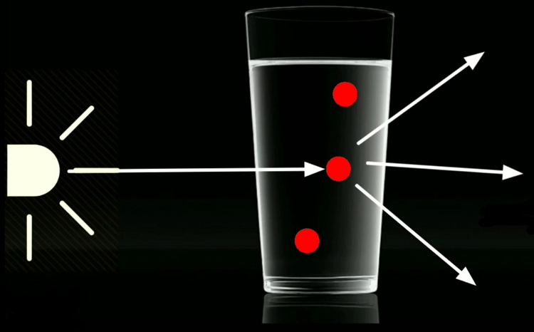
Turbidity is the degree or level of cloudiness or haziness of a liquid. This happens due to the presence of large numbers of invisible particles (which the naked eye), similar to white smoke in the air. When light passes through liquids, light waves get scattered due to the presence of these tiny particles. The turbidity of a liquid is directly proportional to the free suspended particles; that is, if the number of particles increases, turbidity will also increase.
Understanding turbidity is crucial for:
- Water quality measurement - An increase in turbidity means the water is contaminated
- Health monitoring - Turbid water has the potential for harmful microorganisms
- Industrial purposes - Process control and quality assurance
- Environmental monitoring - Detection of pollution in water systems
Measuring Turbidity using Arduino
As I mentioned earlier, turbidity happens due to the scattering of light waves. In order to measure the turbidity, we should measure the scattering of light. Turbidity is usually measured in nephelometric turbidity units (NTU) or Jackson turbidity units (JTLJ), depending on the method used for measurement. The two units are roughly equal. The turbidity sensor module measures this scattering to determine water clarity.
Key units of measurement include:
- NTU (Nephelometric Turbidity Units) - Standard Unit of measurement
- JTU (Jackson Turbidity Units) - Analogous scale of measurement
- General turbidity levels: 0-4000 NTU for most of what we do.
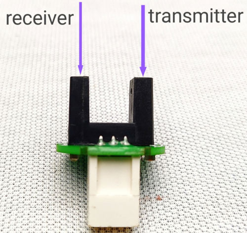
Now let's see how a turbidity sensor works. It has two parts: a transmitter and a Receiver. The transmitter consists of a light source, typically an LED and a driver circuit. On the receiver end, there is a light detector, like a photodiode or an LDR. We place the solution between the transmitter and receiver.
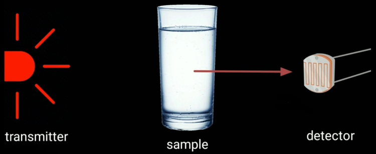
Transmitter simply transmits the light, that light waves pass through the solution, and the receiver receives the light. Normally (without the presence of a solution), the transmitted light is completely received on the receiver side. But in the presence of a turbid solution, the amount of transmitted light is very low. That is, on the receiver side, we get only a low-intensity light, and this intensity is inversely proportional to turbidity. So we can measure the turbidity by measuring the light intensity. If the light intensity is high, the solution is less turbid, and if the light intensity is very low, that means the solution is more turbid.
Components Needed for a Water Turbidity Sensor Arduino
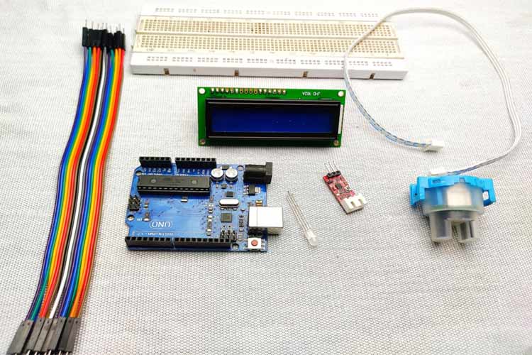
| Component | Quantity | Purpose |
|---|---|---|
| Turbidity sensor module | 1 | Main sensing element |
| Arduino Uno/Nano | 1 | Microcontroller |
| 16×2 I2C LCD Display | 1 | Data visualization |
| RGB LED (Common Cathode) | 1 | Status indication |
| Breadboard | 1 | Circuit prototyping |
| Jumper Wires | 10-15 | Connections |
| Resistors (220Ω) | 3 | LED current limiting |
Turbidity Sensor Module Overview
The turbidity sensor used in this project is shown below.
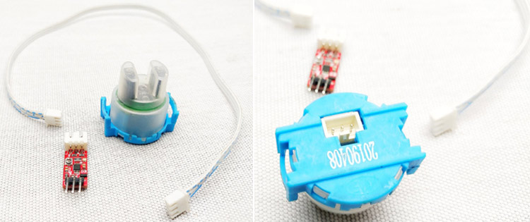
As you can see, this turbidity sensor module comes with 3 parts. A waterproof lead, a driver circuit, and a connecting wire. The testing probe consists of both the transmitter and receiver.
The above image shows, this type of module uses an IR diode as a light source and an IR receiver as a detector. But the working principle is the same as before. The driver part (shown below) consists of an op-amp and some components which amplify the detected light signal.
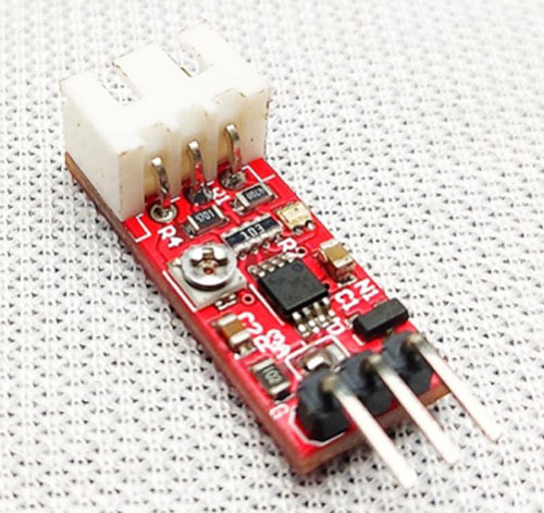
The actual sensor can be connected to this module by using a JST XH connector. It has three pins: VCC, ground, and output. Vcc connects to the 5V and ground to ground. The output of this module is an analog value that is it changes according to the light intensity.
Turbidity Sensor Module Specifications
| Parameter | Value | Notes |
|---|---|---|
| Operating Voltage | 5V DC | Arduino compatible |
| Current Consumption | 30mA (MAX) | Low power operation |
| Operating Temperature | -30°C to 80°C | Wide temperature range |
| Output Type | Analog (0-5V) | Direct Arduino connection |
| Detection Range | 0-4000 NTU | Suitable for most applications |
| Response Time | <500ms | Fast measurement |
Complete Turbidity Sensor Arduino Circuit Diagram
The complete schematic to connect the Turbidity sensor to Arduino is shown below. The circuit was designed using EasyEDA.

This is a very simple circuit diagram. The output of the turbidity sensor is analog, so that connected to Arduino's A0 pin. The I2C LCD is connected to the I2C pins of Arduino, that is SCL to A5 and SDA to A4. Then the RGB LED is connected to digital pins D2, D3, and D4. After the connections are done, my hardware setup looks like this.
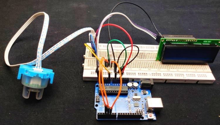
Connect the VCC of the sensor to Arduino 5V, then connect the ground to the ground. The output pin of the sensor is connected to analog 0 of the Arduino. Next, connect the VCC and ground of the LCD module to 5V and the ground of the Arduino. Then SDA to A4 and SCL to A5; these two pins are the I2C pins of Arduino. Finally, connect the ground of the RGB LED to the ground of Arduino and connect green to D3, blue to D4, and red to D5.
Turbidity Sensor Arduino Code: Complete Programming Guide
The plan is to display the turbidity values from 0 to 100. That is, the meter should display 0 for pure liquid and 100 for highly turbid ones. This Arduino code is also very simple, and the complete code can be found at the bottom of this page.
First, I included the I2C liquid crystal library because we are using an I2C LCD to minimise the connections.
#include <LiquidCrystal_I2C.h>Then I set an integer for sensor input.
int sensorPin = A0;In the setup section, I defined the pins.
pinMode(3,OUTPUT);
pinMode(4,OUTPUT);
pinMode(5,OUTPUT);
In the loop section, as I mentioned earlier, the output of the sensor is an analog value. So we need to read those values. With the help of the Arduino AnalogRead function, we can read the output values in the loop section.
int sensorValue =analogRead(sensorPin);First, we need to understand the behaviour of our sensor, which means we need to read the minimum value and maximum value of the turbidity sensor. We can read that value on the serial monitor using serial.println function.
To get these values, first, read the sensor freely, that is, without any solution. I got a value around 640, and after that, I placed a black substance between the transmitter and receiver, and we got a value that is the minimum value; usually, that value is zero. So we got 640 as the maximum and zero as the minimum. Now we need to convert these values to 0-100
For that, I used the map function of Arduino.
int turbidity = map(sensorValue, 0,640, 100, 0);Then I displayed that values in the LCD.
  lcd.setCursor(0, 0);
  lcd.print("turbidity:");
  lcd.print("   ");
  lcd.setCursor(10, 0);
  lcd.print(turbidity);
After that, with the help of if conditions, I gave different conditions.
if (turbidity < 20)
 {
    digitalWrite(2, HIGH);
    digitalWrite(3, LOW);
    digitalWrite(4, LOW);
    lcd.setCursor(0, 1);
    lcd.print(" its CLEAR ");
}
This will activate the green LED and display "it's clear" on the LCD if the turbidity value is below 20.
if ((turbidity > 20) && (turbidity < 50))
{
    digitalWrite(2, LOW);
    digitalWrite(3, HIGH);
    digitalWrite(4, LOW);
    lcd.setCursor(0, 1);
    lcd.print(" its CLOUDY ");
  }
This will activate the blue LED and display "it's cloudy" on the LCD if the turbidity value is between 20 and 50.
if ((turbidity > 50)
{
    digitalWrite(2, LOW);
    digitalWrite(3, HIGH);
    digitalWrite(4, LOW);
    lcd.setCursor(0, 1);
    lcd.print(" its DIRTY ");
  }
This will activate the red LED and display "it's dirty" on the LCD if the turbidity value is greater than 50, as shown below.
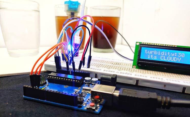
Just follow the circuit diagram and upload the code. If everything goes correctly, you should be able to measure the turbidity of water, and the LCD should display the quality of the water as shown above.
Advanced Applications and Improvements
Some IoT Integration Models
- WiFi connectivity by ESP8266 or ESP32.
- Log data on SD card or cloud storage.
- Remote monitoring on a smartphone app.
- Alert configurations for any change in water quality.
Additional Sensors Integration
| Sensor Type | Purpose | Arduino Pin |
|---|---|---|
| pH Sensor | Acidity measurement | A1 |
| TDS Sensor | Dissolved solids | A2 |
| Temperature | Water temperature | A3 |
| Flow Sensor | Water flow rate | D7 |
Technical Summary And GitHub Repository
Our Technical Summary provides a concise overview of a project’s objectives, design, and implementation details, making it easier to understand the core functionality. The GitHub Repository serves as a centralised platform to host source code, documentation, and version control for collaborative development on access to the project’s resources.


Commonly Asked Questions on the Turbidity Sensor Arduino
⇥ 1. What is the precision of a turbidity sensor Arduino setup?
Arduino turbidity sensors will return results that approximate a quantifiable value that can be claimed to have accuracy of ±5-10% when calibrated with reference standards, but primarily for comparative purposes rather than laboratory quality.
⇥ 2. How do I calibrate my water turbidity sensor Arduino for different types of water?
Calibrate with distilled water as the clear reference (0% turbidity) and the completely blocked sensor as maximum turbidity (100%). Then change your calibration constants in the code based on your sensor's readings.
⇥ 3. Can I use this turbidity sensor module to test drinking water?
The turbidity sensor Arduino circuit will give you a general indication of water quality. But if your interest is in drinking water safety, you will need to add to that with professional tests and other parameters, like pH, TDS, and bacterial content.
⇥ 4. What's the difference between NTU and percentage when measuring turbidity?
NTU (Nephelometric Turbidity Units) is the scientific standard, and percentage is a simplification. Our code produces both readings to share with friends and for scientific use.
⇥ 5. How often should I clean the turbidity sensor module?
Clean the sensor probe with distilled water and a soft cloth once a week if you use the bulb and are doing an actual turbidity measurement. If you are using it for continuous sensing, you should use a cleaning cycle automatically or use a self-cleaning version of the sensor.
⇥ 6. Will the Arduino turbidity sensor work outdoors?
Yes. You just need to make sure to use a weatherproof enclosure for the electronics, and the sensor probes are rated IP68. Note, you would want to consider a temperature compensation to get accurate outdoor turbidity readings, depending on the temperature of the season.
Do note that this turbidity meter displays the percentage of turbidity, and it might not be an accurate industrial value, but still, it can be used to compare the water quality of two waters. The complete working of this project can be found in the video below. Hope you enjoyed the tutorial and learn something useful. If you have any questions, you can leave them in the comment section below or use the CircuitDigest forums for posting your technical questions or starting a relevant discussion.
Related Arduino Water Monitoring Projects
Take on more practical builds that expand your understanding of environmental sensing with Arduino. These projects show how to log data, track rainfall, and detect water levels, giving you a broader toolkit for analyzing and managing water quality in real-world scenarios.

Log Temperature, Humidity and Time on SD Card and Computer using Arduino
Here is the Arduino Data Logger Project covered with circuit diagram and code to learn how we can log temperature and humidity to SD card at a specific interval of time.

Rain Sensor Interfacing with Arduino
Rain Drop Sensor acts as a switch when raindrops fall to the sensor, other than that with slight tweaks in the code it can also measure the intensity of the rainfall. We Interfaced the Rain sensor with Arduino to get the analog and digital output.

Interfacing Water Level Sensor with Arduino
In this tutorial, we are going to interface a water level sensor with an Arduino to measure the water level and in the process, we will let you know the details about this sensor and its working.
Complete Project Code
#include <LiquidCrystal_I2C.h>
LiquidCrystal_I2C lcd(0x27, 2, 16);
int sensorPin = A0;
void setup()
{
  Serial.begin(9600);
  lcd.begin();
  pinMode(2, OUTPUT);
  pinMode(3, OUTPUT);
  pinMode(4, OUTPUT);
}
void loop() {
  int sensorValue = analogRead(sensorPin);
  Serial.println(sensorValue);
  int turbidity = map(sensorValue, 0, 750, 100, 0);
  delay(100);
  lcd.setCursor(0, 0);
  lcd.print("turbidity:");
  lcd.print("   ");
  lcd.setCursor(10, 0);
  lcd.print(turbidity);
  delay(100);
  if (turbidity < 20) {
    digitalWrite(2, HIGH);
    digitalWrite(3, LOW);
    digitalWrite(4, LOW);
    lcd.setCursor(0, 1);
    lcd.print(" its CLEAR ");
  }
  if ((turbidity > 20) && (turbidity < 50)) {
    digitalWrite(2, LOW);
    digitalWrite(3, HIGH);
    digitalWrite(4, LOW);
    lcd.setCursor(0, 1);
    lcd.print(" its CLOUDY ");
  }
  if (turbidity > 50) {
    digitalWrite(2, LOW);
    digitalWrite(3, LOW);
    digitalWrite(4, HIGH);
    lcd.setCursor(0, 1);
    lcd.print(" its DIRTY ");
  }
}Comments
Hello, i got the exact same sensor but it is giving out 540 while not in any solution. and if its blocked the values are not changing

code not working if you use DFRobot analog turbidity sensor.