

Agriculture is the backbone of our country and it is very important to know the parameter of soil and water for efficient harvesting. The various parameters that can be monitored are Soil moisture, pH of water, Temperature, etc. We previously measured these parameters in different tutorials but today we will not only combining them but also display them on a webpage so that they can be monitored from anywhere in the world.
So before starting with this smart water quality monitoring system using Arduino project, you can also check our previous projects to get a better understanding:
- IoT based Smart Irrigation System using Soil Moisture Sensor and ESP8266
- Arduino based Automatic Plant Irrigation System
- pH Meter using Arduino Uno
Materials Used
- Arduino UNO
- NodeMCU
- Gravity Analog pH sensor
- DS18B20 temperature sensor
- Soil moisture sensor
- Power supply
- Jumpers
- Breadboard
Working of DS18B20 Temperature Sensor
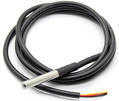
DS18B20 is a single wire temperature sensor, as this can be interfaced with microcontroller or Arduino using single data wire. This is available in a waterproof and Non-waterproof format.
Technical Specifications:
- Temperature range: -55 to 125°C
- bit selectable resolution: 9-12 bit
- 1-Wire interface
- Unique 64-bit address enables multiplexing
- Accuracy: ±0.5°C
- Operating Voltage: 3-5 VDC
- Conversion time: 750ms at 12-bit
Pinout of DS18B20:
- VCC: Power input: (3.3 – 5) V DC
- Ground: Ground pin of the circuit
- Data: 1 Wire temperature value data output pin
Other temperature sensors like LM35 or DHT11 can also be used to measure the temperature but DS18B20 is available in a waterproof casing so it is a perfect choice to monitor the temperature of the water. To learn more about DS18B20, check our previous project where DS18B20 is used with Raspberry Pi and PIC microcontroller to build a digital thermometer.
What is PH Value?
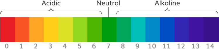
The unit that we use to measure the acidity of a substance is called pH. The term “H” is defined as the negative log of the hydrogen ion concentration. The range of pH can have values from 0 to 14. A pH value of 7 is neutral, as pure water has a pH value of exactly 7. Values lower than 7 are acidic and values greater than 7 are basic or alkaline.
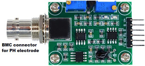
How Does Gravity Analog pH Sensor work?
Analog pH sensor is designed to measure the pH value of a solution and show the acidity or alkalinity of the substance. It is commonly used in various applications such as agriculture, wastewater treatment, industries, environmental monitoring, etc. The module has an on-board voltage regulator chip which supports the wide voltage supply of 3.3-5.5V DC, which is compatible with 5V and 3.3V of any control board like Arduino. The output signal is being filtered by hardware low jitter. We previously used a PH sensor with Arduino to measure the pH value of liquid solution.
Technical Features:
Signal Conversion Module:
- Supply Voltage: 3.3~5.5V
- BNC Probe Connector
- High Accuracy: ±0.1@25°C
- Detection Range: 0~14
PH Electrode:

- Operating Temperature Range: 5~60°C
- Zero(Neutral) Point: 7±0.5
- Easy calibration
- Internal Resistance: <250MΩ
PH Signal Conversion Board:
Pin Description:
V+: 5V DC input
G: Ground pin
Po: pH analog output
Do: 3.3V DC output
To: Temperature output
PH Electrode Construction:
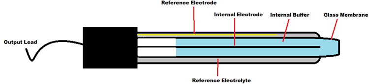
The construction of a pH sensor is shown above. The pH Sensor looks like a rod usually made of a glass material having a tip called “Glass membrane”. This membrane is filled with a buffer solution of known pH (typically pH = 7). This electrode design ensures an environment with the constant binding of H+ ions on the inside of the glass membrane. When the probe is dipped into the solution to be tested, hydrogen ions in the test solution start exchanging with other positively charged ions on the glass membrane, which creates an electrochemical potential across the membrane which is fed to the electronic amplifier module which measures the potential between both electrodes and converts it to pH units. The difference between these potentials, the voltage displayed on the pH sensor, determines the pH value based on the Nernst equation.
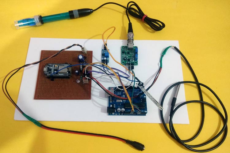
Circuit Diagram
Circuit diagram for this Arduino based Smart Water Quality Monitoring System is given below:

Connection of PH Signal Conversion Board with Arduino:
The connection between Arduino and PH signal conversion board is shown in the table below.
|
Arduino |
PH Sensor board |
|
5V |
V+ |
|
GND |
G |
|
A0 |
Po |
Programming for Soil Monitoring using IoT
There are two parts of programming in this Smart Water Monitoring System using IoT. In the first part, Arduino is programmed and in the second part, NodeMCU will be programmed. Complete code for both Arduino and NodeMCU along with the video is given at the end of this tutorial. The stepwise description of the code is given below.
Arduino Programming:
First of all, include all the header files, which will be required throughout the code. Here we are using onwire.h and DallasTemperature.h library for a DS18B20 temperature sensor. This can be downloaded from the links given and included in the Arduino library. Similarly, we are using ArduinoJson.h library for sending JSON data from the transmitter to the receiver side.
#include <OneWire.h>
#include <DallasTemperature.h>
#include <ArduinoJson.h>
Next, define the connection pin of Arduino, where the output pin of the DS18B20 sensor will be connected, which is digital pin 2 in my case. Then, objects for onewire class and DallasTemperature class are defined which will be required in the coding for temperature measurement.
OneWire oneWire(2);
DallasTemperature temp_sensor(&oneWire);
Next, the calibration value is defined, which can be modified as required to get an accurate pH value of solutions.
float calibration_value = 21.34;
Then a JSON Object is defined which will be required for sending parameters from the Transmitter part to the Receiver part.
StaticJsonBuffer<1000> jsonBuffer;
JsonObject& root = jsonBuffer.createObject();
Inside loop(), read 10 sample Analog values and store them in an array. This is required to smooth the output value.
for(int i=0;i<10;i++)
 {
 buffer_arr[i]=analogRead(A0);
 delay(30);
 }
Then, we have to sort the Analog values received in ascending order. This is required because we need to calculate the running average of samples in the later stage.
 for(int i=0;i<9;i++)
 {
 for(int j=i+1;j<10;j++)
 {
 if(buffer_arr[i]>buffer_arr[j])
 {
 temp=buffer_arr[i];
 buffer_arr[i]=buffer_arr[j];
 buffer_arr[j]=temp;
 }
 }
 }
Finally, calculate the average of a 6 centre sample Analog values. Then this average value is converted into actual pH value and stored in a variable.
 for(int i=2;i<8;i++)
 avgval+=buffer_arr[i];
 float volt=(float)avgval*5.0/1024/6;
 float ph_act = -5.70 * volt + calibration_value;
To send a command to get the temperature values from the sensor, requestTemperatures() function is used.
temp_sensor.requestTemperatures();
Now, analog values from the soil moisture sensor are read and this is mapped to percentage using map() function as shown below:
int moisture_analog=analogRead(A1);
int moist_act=map(moisture_analog,0,1023,100,0);
Finally, the parameters which are to be sent to NodeMCU, are inserted into JSON objects and they are sent via serial communication using root.printTo(Serial) command.
root["a1"] = ph_act;
root["a2"] = temp_sensor.getTempCByIndex(0);
root["a3"] = moist_act;
root.printTo(Serial);
Serial.println("");
Programming NodeMCU
After the successful completion of the hardware setup and Arduino programming, now it’s time to program the NodeMCU.
Note: Remove the Transmitter and Receiver connections between Arduino and NodeMCU before uploading the code.
To upload code in NodeMCU, follow the steps below:
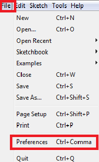
1. Open Arduino IDE, then go to File–>Preferences–>Settings.
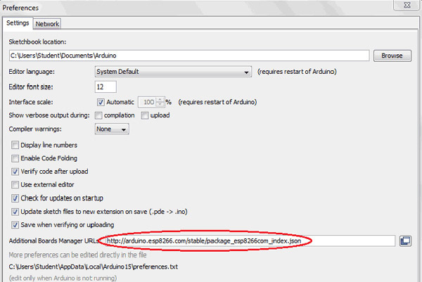
2. Type https:// arduino.esp8266.com/stable/package_esp8266com_index.json in the ‘Additional Board Manager URL’ field and click ‘Ok’.
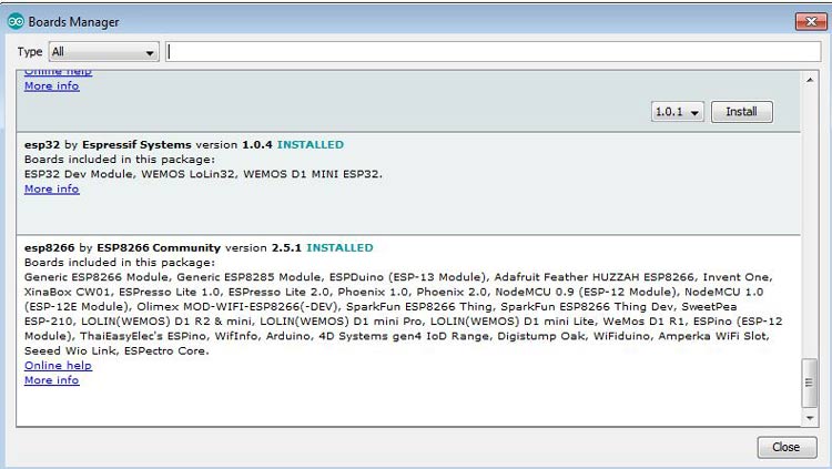
3. Now go to Tools > Board > Boards Manager. In the Boards Manager window, Type ESP8266 in the search box, select the latest version of the board, and click on install.
4. After installation is complete, go to Tools ->Board -> and select NodeMCU 1.0(ESP-12E Module). Now you can program NodeMCU with Arduino IDE.
First, we have to include all the required library files in our code. ESP8266 library is included for both client and server configurations and Arduinojson.h for receiving the JSON data.
#include<ESP8266WiFi.h>
#include<WiFiClient.h>
#include<ESP8266WebServer.h>
#include <ArduinoJson.h>
Then create the ESP8266WebServer class object with the name server and default port number 80.
ESP8266WebServer server (80);
Now, declare network credentials i.e SSID and password. It is required to connect our NodeMCU to the internet.
const char* ssid = "admin";
const char* password = "12345678";
Then, to connect NodeMCU to the internet, call WiFi.begin and pass network SSID and password as its arguments. Check for the successful network connection using WiFi.status() and after a successful connection, print a message in Serial Monitor with IP address.
Serial.begin(115200);
WiFi.begin(ssid, password);
while (WiFi.status() != WL_CONNECTED)
  {
  delay(500);
  Serial.print(".");
  }
  Serial.print(WiFi.localIP());
In the next step, an HTML page for this Water Monitoring System using IOT is created as shown below, which has an HTML table to show pH value, Temperature, and soil moisture. The HTML page is stored in a string variable so that it can be sent back on client request using the server.send() function.
page = "<html><head><title>IoT Design Pro</title></head><style type=\"text/css\">";
page += "table{border-collapse: collapse;}th {background-color: green ;color: white;}table,td {border: 4px solid black;font-size: x-large;";
page += "text-align:center;border-style: groove;border-color: rgb(255,0,0);}</style><body><center>";
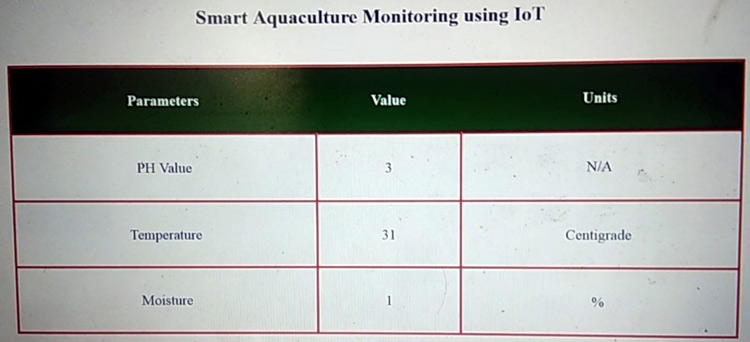
page += "<h1>Smart Aquaculture Monitoring using IoT</h1><br><br><table style=\"width: 1200px;height: 450px;\"><tr>";
page += "<th>Parameters</th><th>Value</th><th>Units</th></tr><tr><td>PH Value</td><td>"+String(data1)+"</td><td>N/A</td></tr>";
page += "<tr><td>Temperature</td><td>"+String(data2)+"</td><td>Centigrade</td></tr><tr><td>Moisture</td><td>"+String(data3)+"</td><td>%</td>";
page += "<meta http-equiv=\"refresh\" content=\"3\">";
server.send(200, "text/html", page);
Now, check for valid JSON data reception, from the Transmitter side. If no valid data is found, a message will be displayed on the serial monitor.
if (root == JsonObject::invalid())
  {
    return;
    Serial.println("invalid");
  }
Otherwise, data received are assigned to individual variables and appended in the HTML webpage for real-time display.
root["a1"] = ph_act;
root["a2"] = temp_sensor.getTempCByIndex(0);
root["a3"] = moist_act;
At the end of the loop, to handle the client request, we have to call server.handleClient(). It will handle new requests and check them.
server.handleClient();
Below is the HTML page will be shown in a web browser:
So this is how a smart water quality monitoring system can be built easily with few components. Complete code and video are given below.
Complete Project Code
# Arduino Code
#include <OneWire.h>
#include <DallasTemperature.h>
#include <ArduinoJson.h>
OneWire oneWire(2);
DallasTemperature temp_sensor(&oneWire);
float calibration_value = 21.34;
int phval = 0;
unsigned long int avgval;
int buffer_arr[10], temp;
void setup()
{
  Serial.begin(9600);
  temp_sensor.begin();
}
StaticJsonBuffer<1000> jsonBuffer;
JsonObject& root = jsonBuffer.createObject();
void loop() {
  for (int i = 0; i < 10; i++)
  {
    buffer_arr[i] = analogRead(A0);
    delay(30);
  }
  for (int i = 0; i < 9; i++)
  {
    for (int j = i + 1; j < 10; j++)
    {
      if (buffer_arr[i] > buffer_arr[j])
      {
        temp = buffer_arr[i];
        buffer_arr[i] = buffer_arr[j];
        buffer_arr[j] = temp;
      }
    }
  }
  avgval = 0;
  for (int i = 2; i < 8; i++)
    avgval += buffer_arr[i];
  float volt = (float)avgval * 5.0 / 1024 / 6;
  float ph_act = -5.70 * volt + calibration_value;
  temp_sensor.requestTemperatures();
  int moisture_analog=analogRead(A1);
  int moist_act=map(moisture_analog,0,1023,100,0);
  root["a1"] = ph_act;
  root["a2"] = temp_sensor.getTempCByIndex(0);
  root["a3"] = moist_act;
  root.printTo(Serial);
  Serial.println("");
}


NodeMCU Code:
#include<ESP8266WiFi.h>
#include<WiFiClient.h>
#include<ESP8266WebServer.h>
#include <ArduinoJson.h>
const char* ssid = "admin";//Replace with your network SSID
const char* password = "12345678";//Replace with your network password
ESP8266WebServer server(80);
String page = "";
int data1, data2, data3;
void setup()
{
  Serial.begin(9600);
  WiFi.begin(ssid, password);
while (WiFi.status() != WL_CONNECTED)
  {
  delay(500);
  Serial.print(".");
  }
  Serial.println(WiFi.localIP());
  server.on("/", []()
  {
    page = "<html><head><title>IoT Design</title></head><style type=\"text/css\">";
    page += "table{border-collapse: collapse;}th {background-color:  green ;color: white;}table,td {border: 4px solid black;font-size: x-large;";
    page += "text-align:center;border-style: groove;border-color: rgb(255,0,0);}</style><body><center>";
    page += "<h1>Smart Aquaculture Monitoring using IoT</h1><br><br><table style=\"width: 1200px;height: 450px;\"><tr>";
    page += "<th>Parameters</th><th>Value</th><th>Units</th></tr><tr><td>PH Value</td><td>"+String(data1)+"</td><td>N/A</td></tr>";
    page += "<tr><td>Temperature</td><td>"+String(data2)+"</td><td>Centigrade</td></tr><tr><td>Moisture</td><td>"+String(data3)+"</td><td>%</td>";
    page += "<meta http-equiv=\"refresh\" content=\"3\">";
    server.send(200, "text/html", page);
  });
  server.begin();
}
void loop()
{
  StaticJsonBuffer<1000> jsonBuffer;
  JsonObject& root = jsonBuffer.parseObject(Serial);
  if (root == JsonObject::invalid())
  {
    return;
    Serial.println("invalid");
  }
  data1 = root["a1"];
  data2 = root["a2"];
  data3 = root["a3"];
  Serial.println(data1);
  Serial.println(data2);
  Serial.println(data3);
  server.handleClient();
}Comments
if i want to send the ph sensor data to thingspeak using nodemcu and arduino means.what will be the changes in the code?
how to connect to html
Good day! We are a group of beginner electronics and programming enthusiasts who are currently working on a project based on your amazing work titled "Arduino & NodeMCU Based Smart Water Quality Monitoring System using IoT" that we found on CircuitDigest.
We found the project very inspiring and helpful. However, we noticed that the complete code and some of the connection details—especially how and where to connect the temperature sensor (DS18B20)—were not clearly mentioned on the page. We would also appreciate some guidance on how to connect the temperature readings to the HTML web interface you presented in the project.
We hope you could kindly share the complete code and a detailed wiring diagram for the sensors, particularly the temperature sensor. We are still learning, and your guidance would be a huge help for us to understand and complete the project properly.
Thank you very much for your time and for sharing such a great project with the community!
Hi, the complete code is already there in the code section (Scroll through the cod tag). There are two codes in it. One is for the Arduino and the other is for the ESP8266. Copy the relatvent section into the Arduinom IDE and compile and flash it to the corresponding development board. The transistor like symbol in the schematics represents the DS18B20. The data pin from it is connected to the D2 pin of the Arduino Uno. The HTML page is already embedded in the given code for ESP8266.

#include <OneWire.h>
^~~~~~~~~~~
compilation terminated.
Compilation error: exit status 1
how to rectify the error?