Published February 24, 2022
0

This is a two-channel touch & two-channel wifi home automation project. This project can control four appliances via two touch sensors and a smartphone(wifi). We have built many such project, here are some example
- RF Controlled Home Appliances
- Smart Phone controlled Home Appliances with Energy Meter using NodeMCU
- Temperature Controlled AC Home Appliances using Arduino and Thermistor
- Home Automation: Bluetooth controlled Electrical Appliances using Smart Phone
Component Required for Home Automation
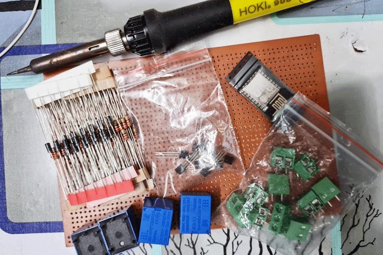
Project Used Hardware
- Blank PCB,
- BC547 Transistor,
- Resistor(220ohm),
- Diode(1N4007),
- Relay(5volt),
- 3pin Terminal,
- SMPS(5volt),
- Touch Sensor(ttp223),
- ESP8266 12E,
- AMS11179(3.3v.),
- 10k resistor
Project Used Software
- arduino ide,
- blynk(legacy)
Project Hardware Software Selection
To set-up the Blynk app, add switches and then first switch-V1 & second switch-V2. To set-up the code, change wifi ssid, password & change auth token given by blynk.
Home Automation Circuit Diagram

To program the ESP8266 12E module, you can use different types of programmers like witty cloud development board, nodemcu, and CP2102 USB to TTL converter.
Complete Project Code
//write the wifi name,password and auth token given by the blynk.
#define BLYNK_PRINT Serial
#include <ESP8266WiFi.h>
#include <BlynkSimpleEsp8266.h>
int relay1 = D1;
int relay2 = D2;
char auth[] = "xxxxxxxxxxxxxxxx";
char ssid[] = "xxxxxxxx";
char pass[] = "xxxxxx";
BLYNK_WRITE(V1) {
  int pinValue = param.asInt();
  digitalWrite(relay1, pinValue);
}
BLYNK_WRITE(V2) {
  int pinValue = param.asInt();
  digitalWrite(relay2, pinValue);
}
void setup() {
  pinMode(relay1, OUTPUT);
  pinMode(relay2, OUTPUT);
  Serial.begin(9600);
  Blynk.begin(auth, ssid, pass);
}
void loop() {
  Blynk.run();
}
