
The Raspberry Pi Pico W is a versatile microcontroller board based on the RP2040 chip, featuring built-in Wi-Fi connectivity. It offers a cost-effective and powerful solution for various IoT projects and prototyping. When combined with sensors like the ultrasonic sensor (e.g., HC-SR04), the Pico W becomes an ideal platform to measure distances, detect objects, and create smart automation applications. In this blog, we will learn how you can interface a Raspberry Pi Pico W to an ultrasonic sensor. We will also take a look on how you can display these ultrasonic values on an OLED screen. So, If you are excited to learn how. Stay tuned. Also check interfacing ultrasonic sensor with Raspberry Pi 2.
The main components which we will require for this project are:-
Breadboard
Raspberry Pi Pico W
Ultrasonic Sensor
Jumper wires
OLED screen(not mandatory)
Ultrasonic Sensor Pinout

The Pinout of Ultrasonic Sensors are as follows:-
VCC This pin is used to supply power to the sensor. It typically requires 5V DC power supply.
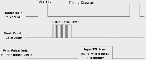
Trig (Trigger) This pin is used to send a trigger signal to the sensor. When a HIGH signal (usually 5V) is applied to this pin, the sensor starts emitting ultrasonic waves.
Echo This pin is used to receive the echo signal from the sensor. When the ultrasonic waves emitted by the sensor hit an object and bounce back, the sensor generates a pulse on this pin.
GND This pin is the ground connection of the sensor and should be connected to the ground (0V) of your circuit.
Ultrasonic Sensor Working
The Ultrasonic Sensor has two transducers one is the transmitter side and the other is the receiver side.
It operates on the principle of sound waves and their reflection. It emits high-frequency ultrasonic waves (usually above 20 kHz) from its transmitter, which then travel through the air. When these waves encounter an obstacle or a surface, they bounce back as echoes. The sensor's receiver detects these returning echoes and measures the time it takes for the waves to travel back.
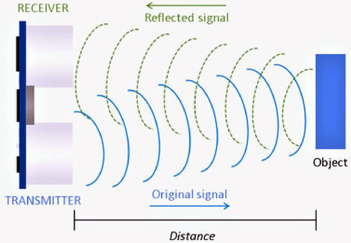
By knowing the speed of sound in the medium (usually air at a given temperature), the sensor can calculate the distance to the object using the formula:
Distance = (Speed of Sound * Time taken for Echo) / 2
The entire process happens rapidly, and the sensor can measure distances in real-time.
Commonly asked Questions about Ultrasonic Sensor
What is the typical range of an ultrasonic sensor?
The range of ultrasonic sensors can vary, but common HC-SR04 sensors have a range of approximately 2 to 400 centimeters. Some specialized sensors can have longer ranges, reaching several meters.
Can ultrasonic sensors detect multiple objects simultaneously?
Yes, ultrasonic sensors can detect multiple objects within their range. However, they may not be able to distinguish between individual objects in close proximity, as the returning sound waves can overlap. Advanced signal processing techniques can be used to overcome this limitation.
How do ultrasonic sensors compare to other proximity sensors like infrared (IR) sensors?
Ultrasonic sensors offer advantages in longer range and non-contact detection compared to IR sensors. IR sensors can be affected by ambient light and surfaces, while ultrasonic sensors work well in various lighting conditions and can detect transparent objects as well.
Circuit Diagram - Raspberry Pi Pico W Interfacing with an Ultrasonic Sensor

Connect the VCC pin of the HC-SR04 to the Vbus pin on the Pico W.
Connect the GND pin of the HC-SR04 to the GND pin on the Pico W.
Connect the TRIG pin of the HC-SR04 to any GPIO pin on the Pico W (e.g., GPIO 0 - Pin 1 on the board).
Connect the ECHO pin of the HC-SR04 to another GPIO pin on the Pico W (e.g., GPIO 1 - Pin 2 on the board).
Now let’s move on to the software setup for programming it.
First open the thonny ide.
Download micropython firmware for raspberry pi pico W from official website.
Go to tools> options>interpreter and select raspberry pi pico as interpreter.
Copy paste the below code in thonny ide and save it as ssd1306.py in your board.
Raspberry Pi Pico W and Ultrasonic programming using MicroPython
The below code explains interfacing of Ultrasonic sensor interface with raspberry pi pico w and display the distance on the screen. The complete code is given at the bottom of this blog
from machine import Pin
import utime
These lines import the necessary modules for working with the microcontroller's hardware pins (using machine.Pin) and for managing time (using utime).
trigger = Pin(20, Pin.OUT)
echo = Pin(21, Pin.IN)
Here, the code defines two pins: trigger and echo. The trigger pin (connected to GPIO pin 20) will be used to send out ultrasonic waves, and it's configured as an output pin. The echo pin (connected to GPIO pin 21) will receive the reflected ultrasonic waves, and it's configured as an input pin.
def ultra():
    trigger.low()
    utime.sleep_us(2)
    trigger.high()
    utime.sleep_us(5)
    trigger.low()
This is a function named ultra() that is responsible for sending out the ultrasonic waves. It starts by setting the trigger pin to a low state, then sleeps for 2 microseconds. After that, it sets the trigger pin to a high state for 5 microseconds and immediately sets it back to a low state.
    while echo.value() == 0:
        signaloff = utime.ticks_us()
This loop waits until the echo pin reads a low value, indicating that the ultrasonic wave has been sent and is yet to return. When the echo pin reads a low value, the current timestamp in microseconds is stored in the signaloff variable.
    while echo.value() == 1:
        signalon = utime.ticks_us()
This loop waits until the echo pin reads a high value, indicating that the ultrasonic wave has been reflected back and received. When the echo pin reads a high value, the current timestamp in microseconds is stored in the signalon variable.
    timepassed = signalon - signaloff
    distance = (timepassed * 0.0343) / 2
    print("The distance from object is ", distance, "cm")
Here, the time difference between the signalon and signaloff timestamps is calculated. This time difference represents the round-trip time for the ultrasonic wave. The formula (timepassed * 0.0343) / 2 is used to convert this time difference into distance in centimeters, assuming the speed of sound is approximately 343 meters per second. The calculated distance is then printed out.
while True:
    ultra()
    utime.sleep(1)
In this loop, the ultra() function is repeatedly called to measure the distance using ultrasonic waves. After each distance measurement, the program waits for 1 second using utime.sleep(1) before measuring the distance again. This loop runs indefinitely, continuously measuring and printing distances.
Circuit Diagram - Raspberry Pi Pico W and Ultrasonic Sensor Interfacing with OLED Screen Display

The below code explains interfacing of Ultrasonic sensor and raspberry pi pico w and then displaying the distance value on the OLED screen.
Note: you need to first save the ssd1306.py driver code given below and save it as ssd1306.py in your raspberry pi pico W board
import machine
from machine import Pin, SoftI2C
import ssd1306
import utime
Here, the code imports necessary modules: machine module for hardware control, Pin and SoftI2C classes from machine for controlling pins and I2C communication, ssd1306 for working with an OLED display, and utime for time-related functions.
i2c = machine.SoftI2C(scl=machine.Pin(5), sda=machine.Pin(4))
This line initializes a software-based I2C communication using the SoftI2C class. It specifies the scl (clock) and sda (data) pins connected to GPIO pins 5 and 4, respectively.
pin = machine.Pin(16, machine.Pin.OUT)
pin.value(0)  # set GPIO16 low to reset OLED
pin.value(1)  # while OLED is running, must set GPIO16 in high
These lines set up a GPIO pin (pin 16) to control the OLED display. It first sets the pin low to reset the OLED module, then sets it high to indicate that the OLED is operational.
oled_width = 128
oled_height = 64
oled = ssd1306.SSD1306_I2C(oled_width, oled_height, i2c)
This initializes the OLED display using the ssd1306.SSD1306_I2C class. It specifies the display's width and height (128x64 pixels) and the previously initialized I2C communication.
trigger = Pin(20, Pin.OUT)
echo = Pin(21, Pin.IN)
Similar to the previous code, these lines define the trigger and echo pins for ultrasonic distance measurement.
def ultra():
    # ... (ultrasonic distance measurement code)
    return distance
The ultra() function remains unchanged from the previous explanation. It measures the distance using ultrasonic waves and returns the calculated distance in centimeters.
while True:
    distance_cm = ultra()
    oled.fill(0)
    oled.text("Distance:", 0, 10)
    oled.text("{:.2f} cm".format(distance_cm), 0, 20)
    oled.show()
    utime.sleep(0.2)
This is the main loop of the program. Inside the loop, the ultra() function is called to measure the distance in centimeters. The OLED display is then updated with the distance information, displaying it on the screen. The display is cleared using oled.fill(0) to ensure only the new distance is shown. The oled.text() function is used to render text on the display. Finally, the OLED display is updated with oled.show() and the program waits for 0.2 seconds using utime.sleep(0.2) before taking the next distance measurement. This loop continues indefinitely, constantly updating the displayed distance on the OLED screen.
Projects using Ultrasonic Sensor

Building a Smart Blind Stick using Arduino - Inspired by Shark Tank Torchit
Navigate the world innovatively! Discover how to create a Smart Blind Stick using Arduino, inspired by the Shark Tank Torchit. Our guide takes you through the process step by step, empowering you to build a device that enhances mobility for visually impaired individuals. Whether you're a tech enthusiast or a compassionate maker, this project combines cutting-edge technology with social impact. Join us in crafting a tool that truly makes a difference and learn how Arduino can create meaningful solutions.

Smart Dustbin using Arduino and Ultrasonic Sensor
Revolutionize waste management! Our guide showcases how to craft a Smart Dustbin using Arduino and an Ultrasonic Sensor. Dive into the world of IoT as we lead you through each step, helping you build a sensor-equipped bin that opens up hands-free. Whether you're an eco-conscious individual or a tech enthusiast, this project merges innovation and practicality. Join us in creating a cleaner future with this smart solution that simplifies waste disposal.

Water Level Monitoring of House Overhead Tank from Anywhere in the World
Stay connected to your resources! Our guide demonstrates how to monitor the water level of your house overhead tank from anywhere in the world. With step-by-step instructions, we'll help you set up a remote monitoring system using IoT technology. Whether you're a homeowner or a tech enthusiast, this project combines convenience and innovation. Join us in creating a smarter home and enjoy peace of mind with real-time water level updates at your fingertips.
Complete Project Code
//Complete code of Ultrasonic Raspberry Pi Pico Interfacing
from machine import Pin
import utime
trigger = Pin(20, Pin.OUT)
echo = Pin(21, Pin.IN)
def ultra():
   trigger.low()
   utime.sleep_us(2)
   trigger.high()
   utime.sleep_us(5)
   trigger.low()
   while echo.value() == 0:
       signaloff = utime.ticks_us()
   while echo.value() == 1:
       signalon = utime.ticks_us()
   timepassed = signalon - signaloff
   distance = (timepassed * 0.0343) / 2
   print("The distance from object is ",distance,"cm")
while True:
   ultra()
   utime.sleep(1)

//Complete code of Ultrasonic, raspberry pi Pico and OLED interfacing
import machine
from machine import Pin, SoftI2C
import ssd1306
import utime
i2c = machine.SoftI2C(scl=machine.Pin(5), sda=machine.Pin(4))
pin = machine.Pin(16, machine.Pin.OUT)
pin.value(0)  # set GPIO16 low to reset OLED
pin.value(1)  # while OLED is running, must set GPIO16 in high
oled_width = 128
oled_height = 64
oled = ssd1306.SSD1306_I2C(oled_width, oled_height, i2c)
trigger = Pin(20, Pin.OUT)
echo = Pin(21, Pin.IN)
def ultra():
    trigger.low()
    utime.sleep_us(2)
    trigger.high()
    utime.sleep_us(5)
    trigger.low()
    while echo.value() == 0:
        signaloff = utime.ticks_us()
    while echo.value() == 1:
        signalon = utime.ticks_us()
    timepassed = signalon - signaloff
    distance = (timepassed * 0.0343) / 2
    return distance
while True:
    # Measure the distance
    distance_cm = ultra()
    # Update the OLED display
    oled.fill(0)
    oled.text("Distance:", 0, 10)
    oled.text("{:.2f} cm".format(distance_cm), 0, 20)
    oled.show()
    # Wait for a short interval before taking the next measurement
    utime.sleep(0.2)

// ssd1306.py driver code
# MicroPython SSD1306 OLED driver, I2C and SPI interfaces
from micropython import const
import framebuf
# register definitions
SET_CONTRAST = const(0x81)
SET_ENTIRE_ON = const(0xA4)
SET_NORM_INV = const(0xA6)
SET_DISP = const(0xAE)
SET_MEM_ADDR = const(0x20)
SET_COL_ADDR = const(0x21)
SET_PAGE_ADDR = const(0x22)
SET_DISP_START_LINE = const(0x40)
SET_SEG_REMAP = const(0xA0)
SET_MUX_RATIO = const(0xA8)
SET_COM_OUT_DIR = const(0xC0)
SET_DISP_OFFSET = const(0xD3)
SET_COM_PIN_CFG = const(0xDA)
SET_DISP_CLK_DIV = const(0xD5)
SET_PRECHARGE = const(0xD9)
SET_VCOM_DESEL = const(0xDB)
SET_CHARGE_PUMP = const(0x8D)
# Subclassing FrameBuffer provides support for graphics primitives
# https://docs.micropython.org/en/latest/pyboard/library/framebuf.html
class SSD1306(framebuf.FrameBuffer):
    def __init__(self, width, height, external_vcc):
        self.width = width
        self.height = height
        self.external_vcc = external_vcc
        self.pages = self.height // 8
        self.buffer = bytearray(self.pages * self.width)
        super().__init__(self.buffer, self.width, self.height, framebuf.MONO_VLSB)
        self.init_display()
    def init_display(self):
        for cmd in (
            SET_DISP | 0x00,  # off
            # address setting
            SET_MEM_ADDR,
            0x00,  # horizontal
            # resolution and layout
            SET_DISP_START_LINE | 0x00,
            SET_SEG_REMAP | 0x01,  # column addr 127 mapped to SEG0
            SET_MUX_RATIO,
            self.height - 1,
            SET_COM_OUT_DIR | 0x08,  # scan from COM[N] to COM0
            SET_DISP_OFFSET,
            0x00,
            SET_COM_PIN_CFG,
            0x02 if self.width > 2 * self.height else 0x12,
            # timing and driving scheme
            SET_DISP_CLK_DIV,
            0x80,
            SET_PRECHARGE,
            0x22 if self.external_vcc else 0xF1,
            SET_VCOM_DESEL,
            0x30,  # 0.83*Vcc
            # display
            SET_CONTRAST,
            0xFF,  # maximum
            SET_ENTIRE_ON,  # output follows RAM contents
            SET_NORM_INV,  # not inverted
            # charge pump
            SET_CHARGE_PUMP,