

In this article, let us discuss how to interface WIFI module ESP8266 with a PIC microcontroller. So far you might have been using the ESP8266 module as a standalone microcontroller or might have been using it with the Arduino library. But, when it comes to hardcore embedded system projects we should know how to use it with PIC microcontrollers as well. This will help you to customize your projects in design perspective and at the same time also making it cheap.
The ESP8266 modules comes with a default firmware loaded into it, hence we can program the module using AT commands. These commands have to be sent through a serial communication channel. This channel is established between the PIC and the ESP8266 module by using the USART module in the PIC microcontroller. The whole working will be monitored and reported to the user by using a 16x2 LCD display. Hence, this tutorial assumes that you have some basic knowledge about the USART module in PIC, Interfacing LCD with PIC and using AT commands in ESP8266. If you do not then you can fall back to the linked tutorials to learn them beforehand.
Materials Required:
You would need the following hardware to complete this tutorial
- PIC16F877A
- 20MHz crystal oscillator
- 7805
- LM317
- ESP8266
- 16*2 LCD display
- PicKit3 programmer
- Resistors (1K,220ohm,360ohm)
- Capacitors (1uF, 0.1uF, 33pF)
- Jumper wires
- 12V Adapter to power the PIC and ESP module
Hardware:
The complete schematic of the project is shown here below

The schematics consists of two voltage regulator circuits, one is a +5V regulator which is used to power the PIC microcontroller and the other is a 3.3V regulator which powers the ESP8266 module. The +5V is regulated by using a 7805(Linear Voltage Regulator IC). The 3.3V is regulated by using LM317 (Variable Voltage Regulator). The ESP8266 module consumes a lot of current (~800mA) hence if you are designing your own power supply make sure it can source such high current. Also make sure that the ground pins of the PIC and the ESP8266 module is connected together.
So now we know that the PIC operates on +5V and the ESP8266 operates at 3.3V volts. In order to establish a USART communication between these two modules we need have a 5V - 3.3V logic converter circuit as shown in the above figure. This circuit is nothing but a potential divider which simply converts the incoming +5V to 3.3V. This will prevent the 3.3V tolerable RX pin of ESP8266 from getting +5V.
I have made the PIC and ESP modules on two separate perf boards, as shown in these tutorials. This way I can use them universally for more similar projects
You can follow the same, or build your own board in your style or simply connect the above circuit to a breadboard.
Programming the PIC microcontroller:
In order to program the PIC microcontroller to send “AT commands” serially using USART to the ESP8266 module we have to use a library. This library will save you a lot of hassle, like using the ESP8266 instruction modules to check for each and every AT command and then find a way to transmit them to the ESP module. This library is free software originally developed by Camil Staps and later it was improved and modified by Circuit Digest so that it can be used with our PIC16F877A Microcontroller. You can download it here
The library is still under development, but you can use most of the important AT commands in the ESP8266 firmware. If you find any of the command you need is missing, then let me know it in the comment section and I will try to add it for you. This tutorial will explain you all the commands(so far) that can be used by through this library. Further will also guide you to add your own functions to the library.
Functions in ESP8266 Library:
- Initialize_ESP8266(): This function will Initialize the USART module of the PIC to communicate with the ESP8266 module. It sets the baud rate at 115200 and prepares the Rx and Tx pin of PIC for USART communication.
- _esp8266_putch(): This function is used to send a single character serially to the ESP8266 module. For example, _esp8266_putch(‘a’) will send the character a serially to the ESPmodule.
- _esp8266_getch(): This function is used to get a single character from the ESP module. For example if the ESP is printing “OK” and we use char a =_esp8266_getch(). Then the char ‘o’ will be stored in the variable a.
- ESP8266_send_string(): This function is the string version of _esp8266_putch(). It can send one complete string to the ESP8266 module. For example, ESP8266_send_string(“AT/r/n”) will send the command “AT” to the ESP8266 module.
- esp8266_isStarted(): It is used to check if the PIC can communicate with the ESP module. It send the command “AT” and waits for “OK” if received it returns true else it returns false.
- esp8266_restart(): Resets the ESP8266 module and returns true is reset successful and returns false if not successful.
- esp8266_mode(): Used to set the working mode of the ESP8266 module. As we know it can work in three different modes.
|
esp8266_mode(1): |
Station mode |
|
esp8266_mode(2): |
Soft AP mode |
|
esp8266_mode(3): |
Both Station and AP mode |
- esp8266_connect(): Allows you to connect to a wifi signal. For example esp8266_connect(“home”,”12345678”), will allow your module to connect to the wifi signal named home whose password is 12345678.
- esp8266_disconnect(): This function disconnects you module from any wifi connection that was previously connected
- esp8266_ip(): Gets the IP address and returns it. Use this function if you wanna know the IP address of the ESP8266 module.
- esp8266_start(): This function is used to start a TCP or UDP communication. For example esp8266_start("TCP", "192.168.101.110", 80). Will start a TCP network in that IP and port 80.
- esp8266_send(): This function is used to send information to the TCP/UDP network. The HTML script will be sent using this command. Then this script will appear in the IP address in which the communication was established in prior.
- esp8266_config_softAP(): This function is used to configure the softAP. For example esp8266_config_softAP(“office”,”12345678”); will create a Wifi signal named office and the password 12345678 should be used to access it.
- esp8266_get_stationIP(): This function will return you the IP/MAC address of the clients who are connected to your softAP.
Sample Program:
Now that we have understood the functions of each and every command in the library let us look into a small sample program. In this program we will check if the connection between ESP8266 and PIC is successful and then create a WIFI network (SoftAP) with a preferred name and password. The complete program and the simulation of the same will be explained for your understanding.
Again if you have not read our PIC interfacing with LCD and PIC USART tutorial please read the, before proceeding because only then it will make sense to you.
Since we are just getting started to interface PIC with the ESP8266, I have used an LCD to make sure things are working properly.
do

    {

    Lcd_Set_Cursor(1,1);

    Lcd_Print_String("ESP not found");

    }while (!esp8266_isStarted()); //wait till the ESP send back "OK"

    Lcd_Set_Cursor(1,1);

    Lcd_Print_String("ESP is connected");

    __delay_ms(1500);

    Lcd_Clear();
When we send the “AT” to the ESP8266 module it replies back with a “OK”. This ensures us that the ESP8266 module is connected successfully. The function esp8266_isStarted() is used for the same. We send the signal AT from the PIC and we wait till the ESP module to get alive and send us an OK. If we get an OK we display that the “ESP is connected” on the LCD.
esp8266_mode(2);

    Lcd_Set_Cursor(1,1);

    Lcd_Print_String("ESP set as AP");

    __delay_ms(1500);

    Lcd_Clear();
The above lines of code are used to set the ESP module to work in “soft AP” mode. The function esp8266_mode(2); sends the AT commands “AT+CWMODE=3” to the module and waits for the module to respond with “OK”
/*Configure the AP name and Password*/

    esp8266_config_softAP("CircuitDigest","619007123");

    Lcd_Set_Cursor(1,1);

    Lcd_Print_String("AP configured");

    __delay_ms(1500);

    Lcd_Clear();

    /*AP configured*/
This segment of the code is used to configure the softAP. Here we have named the SSID as “CircuitDigest” and the password as “619007123”. To indicate that the process is complete we will wait for the module to respond with “OK” and then print AP configured onto the LCD screen.
That is it now we have interfaced the ESP8266 module with the PIC MCU and have configured the softAP with a name and password of our choice. As usual lets simulate this code and see how it works.
Simulation output:
We are using the Proteus software to simulate the output. The design file for the same can be found in the attachment.
Since we do not have an ESP8266 module in Proteus library we have use the Serial terminal and respond back as a user to the PIC module. The simulation once completed screen will look like below
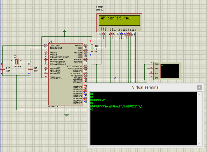
The output of our code is shown in the Virtual terminal. The complete working of the simulation will be explained in the video below.
Output Verification:
Once the program is verified using the simulation, dump it into your PIC microcontroller. Make the connections as shown in the schematics above (Hardware section). You should be able to track your progress through the LCD display.
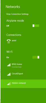
Once the LCD says that the AP is configured we can check that out using the WIFI settings in Phone or Laptop. My laptop shows the following signal as per our program.
That is it guys we have successfully interfaced the ESP8266 module with the PIC Microcontroller. This is a very basic interface and if you want to do any complicated projects using the ESP8266 you might have to add your own libraries or at least add your own functions. Trust me it is very much easy to do so, I will give a brief insight for the same.
Adding functions to the ESP8266 Library:
Adding your own function will help you to send any “AT” command to the ESP8266 module. To proceed with this you need to read the instruction set documentation of the ESP8266 module. You can directly send any AT command that you find in that instruction set manual. But always remember to append “/r/n” at the end of every AT command. For example if your want to establish multiple connections with your ESP module. Then open the instruction set documentation and find our which AT command will do this job for you. Here the command “AT+CIPMUX=1” will allow you to establish multiple connections with your ESP module.
Now all you have to do is send this “AP+CIPMUX=1” to your ESP8266 module using the serial port. The hardcore way of doing this is by simply using the command
_esp8266_print("AT+CIPMUX=1\r\n"")
This will work but is not the best way of doing it. You have to read back what your ESP8266 responds to your command. In our case it will respond with “OK”. So you have to read the incoming data from ESP8266 module and confirm that it is a “OK”. Also you can make this function where the “1” or “0” can be passed as arguments.
Go ahead and try to make your own functions for the library. But if you need help please fell free to use the comment section and I will help you out.
Complete Project Code
#define _XTAL_FREQ 20000000
#define RS RD2

#define EN RD3

#define D4 RD4

#define D5 RD5

#define D6 RD6

#define D7 RD7
#include <xc.h>

#include "esp8266_functions.h"
#pragma config FOSC = HS        // Oscillator Selection bits (HS oscillator)

#pragma config WDTE = OFF       // Watchdog Timer Enable bit (WDT disabled)

#pragma config PWRTE = OFF       // Power-up Timer Enable bit (PWRT enabled)

#pragma config BOREN = ON       // Brown-out Reset Enable bit (BOR enabled)

#pragma config LVP = OFF        // Low-Voltage (Single-Supply) In-Circuit Serial Programming Enable bit (RB3 is digital I/O, HV on MCLR must be used for programming)

#pragma config CPD = OFF        // Data EEPROM Memory Code Protection bit (Data EEPROM code protection off)

#pragma config WRT = OFF        // Flash Program Memory Write Enable bits (Write protection off; all program memory may be written to by EECON control)

#pragma config CP = OFF         // Flash Program Memory Code Protection bit (Code protection off)


//****LCD Functions Developed by Circuit Digest.***///

void Lcd_SetBit(char data_bit) //Based on the Hex value Set the Bits of the Data Lines

{

    if(data_bit& 1)

        D4 = 1;

    else

        D4 = 0;
    if(data_bit& 2)

        D5 = 1;

    else

        D5 = 0;
    if(data_bit& 4)

        D6 = 1;

    else

        D6 = 0;
    if(data_bit& 8)

        D7 = 1;

    else

        D7 = 0;

}
void Lcd_Cmd(char a)

{

    RS = 0;

    Lcd_SetBit(a); //Incoming Hex value

    EN  = 1;

        __delay_ms(4);

        EN  = 0;

}
Lcd_Clear()

{

    Lcd_Cmd(0); //Clear the LCD

    Lcd_Cmd(1); //Move the curser to first position

}
void Lcd_Set_Cursor(char a, char b)

{

    char temp,z,y;

    if(a== 1)

    {

      temp = 0x80 + b - 1; //80H is used to move the curser

        z = temp>>4; //Lower 8-bits

        y = temp & 0x0F; //Upper 8-bits

        Lcd_Cmd(z); //Set Row

        Lcd_Cmd(y); //Set Column

    }

    else if(a== 2)

    {

        temp = 0xC0 + b - 1;

        z = temp>>4; //Lower 8-bits

        y = temp & 0x0F; //Upper 8-bits

        Lcd_Cmd(z); //Set Row

        Lcd_Cmd(y); //Set Column

    }

}
void Lcd_Start()

{

  Lcd_SetBit(0x00);

  for(int i=1065244; i<=0; i--)  NOP();

  Lcd_Cmd(0x03);

    __delay_ms(5);

  Lcd_Cmd(0x03);

    __delay_ms(11);

  Lcd_Cmd(0x03);

  Lcd_Cmd(0x02); //02H is used for Return home -> Clears the RAM and initializes the LCD

  Lcd_Cmd(0x02); //02H is used for Return home -> Clears the RAM and initializes the LCD

  Lcd_Cmd(0x08); //Select Row 1

  Lcd_Cmd(0x00); //Clear Row 1 Display

  Lcd_Cmd(0x0C); //Select Row 2

  Lcd_Cmd(0x00); //Clear Row 2 Display

  Lcd_Cmd(0x06);

}
void Lcd_Print_Char(char data)  //Send 8-bits through 4-bit mode

{

   char Lower_Nibble,Upper_Nibble;

   Lower_Nibble = data&0x0F;

   Upper_Nibble = data&0xF0;

   RS = 1;             // => RS = 1

   Lcd_SetBit(Upper_Nibble>>4);             //Send upper half by shifting by 4

   EN = 1;

   for(int i=2130483; i<=0; i--)  NOP();

   EN = 0;

   Lcd_SetBit(Lower_Nibble); //Send Lower half

   EN = 1;

   for(int i=2130483; i<=0; i--)  NOP();

   EN = 0;

}
void Lcd_Print_String(char *a)

{

    int i;

    for(i=0;a[i]!='\0';i++)

       Lcd_Print_Char(a[i]);  //Split the string using pointers and call the Char function

}

//***End of LCD functions***//

void main()

{

    TRISD = 0x00;

    Lcd_Start();

    Initialize_ESP8266() ;

    Lcd_Set_Cursor(1,1);

    Lcd_Print_String("Circuit Digest");

    Lcd_Set_Cursor(2,1);

    Lcd_Print_String("ESP5266 with PIC");

    __delay_ms(1500);

    Lcd_Clear();


    /*Check if the ESP_PIC communication is successful*/

    do

    {

    Lcd_Set_Cursor(1,1);

    Lcd_Print_String("ESP not found");

    }while (!esp8266_isStarted()); //wait till the ESP send back "OK"

    Lcd_Set_Cursor(1,1);

    Lcd_Print_String("ESP is connected");

    __delay_ms(1500);

    Lcd_Clear();

    /*Yes ESP communication successful*/


    /*Put the module in Soft AP  mode*/

    esp8266_mode(2);

    Lcd_Set_Cursor(1,1);

    Lcd_Print_String("ESP set as AP");

    __delay_ms(1500);

    Lcd_Clear();

    /*Module set as AP */


    /*Configure the AP name and Password*/

    esp8266_config_softAP("CircuitDigest","619007123");

    Lcd_Set_Cursor(1,1);

    Lcd_Print_String("AP configured");

    __delay_ms(1500);

    /*AP configured*/


    while(1)

    {

        //do nothing

    }
}

when I put this into mp lab, every time I got this error.
CLEAN SUCCESSFUL (total time: 0ms)
nbproject/Makefile-impl.mk:43: *** missing separator. Stop.
pls, can someone help me?
[email protected]