DC motors are the most widely used motors. These motors can be found almost everywhere from small projects to advanced robotics. We previously interfaced DC Motor with many other microcontrollers like Arduino, Raspberry pi and used it in many robotic projects. Today we learn to control DC motor with AVR Microcontroller Atmega16. But before going ahead let’s know more about DC motor.
What is a DC motor?
DC Motor is a device which transforms electrical energy into mechanical energy. Specifically, a DC motor uses DC current to convert electrical energy into mechanical energy. The basic principle of motor is the interaction between the magnetic field and current to produce a force within the motor which helps the motor to rotate. So when the electric current is passed through a coil in a magnetic field, a magnetic force is generated which produces a torque resulting in the movement of motor. The direction of the motor is controlled by reversing the current. Also its speed can be varied by varying supplied voltage. Since microcontrollers have PWM pins, so it can be used to control the speed of motor.
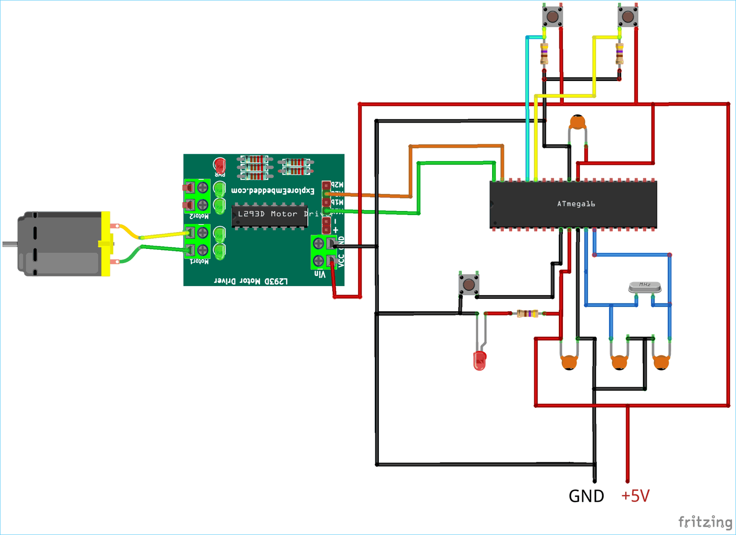
In this tutorial, DC motor operation will be demonstrated with Atmega16. L293D motor driver will be used to reverse the direction of the current thus the direction of movement. The L293D motor driver uses H-Bridge circuit configuration which outputs required current to Motor. Two push buttons are used to select the direction of motor. One of the push button is used to select the clock wise rotation and the other one is used to select the anti-clock operation of DC motor.

Components Required
- DC Motor (5V)
- L293D Motor Driver
- Atmega16 Microcontroller IC
- 16Mhz Crystal Oscillator
- Two 100nF Capacitors
- Two 22pF Capacitors
- Push Button
- Jumper Wires
- Breadboard
- USBASP v2.0
- Led(Any Color)
Circuit Diagram
Programming Atmega16 for DC Motor control
The DC motor is interfaced using L293D motor driver. DC motor will rotate in two directions when respective push button is pressed. The one push button will be used to rotate DC motor in Clock Wise direction and the another push button will be used to rotate DC motor in Counter Clock wise direction. Firstly define CPU frequency of microcontroller and include all necessary libraries.
#define F_CPU 16000000UL
#include<avr/io.h>
#include<util/delay.h>
Then, use one variable to keep track of push button pressed status. This variable will be used to define direction of motor.
int i;
Select input/output mode of GPIO using data direction register. Initially, make output of Motor pin as low to avoid starting up of motor without pressing push button.
DDRA = 03;
PORTA &= ~(1<<1);
PORTA &= ~(1<<0);
Check if 1st push button is pressed connected to PORTA4 of Atmega16 and store the status of push button in variable.
if(!bit_is_clear(PINA,4))
{
     i = 1;
     PORTA &= ~(1<<1);
     _delay_ms(1000);
}
Similarly check if 2nd push button is pressed connected to PORTA5 of Atmega16 and store the status of push button in variable.
  else if (!bit_is_clear(PINA,5))
     {
         i = 2;
         PORTA &= ~(1<<0);
        _delay_ms(1000);
     }
If status of the 1st button is true then rotate DC motor in Clock wise direction and if status of the second push button is true then rotate DC motor in anti-clock wise.
if (i == 1)
{
    PORTA |= (1<<0);
    PORTA &= ~(1<<1);
}
   else if (i == 2)
 {
     PORTA |= (1<<1);
     PORTA &= ~(1<<0);
 }
You can connect motor pins to any GPIO pin depending upon the GPIO used. Also it is important to use Motor Driver IC to decrease the load on the microcontroller as microcontrollers are not capable of providing required current to run DC motors. For more detail and other projects based on DC motors, please visit given link.

Complete code and Demonstration Video is given below.
Complete Project Code
/* Interfacing DC Motor with Atmega16
Circuit Digest(circuitdigest.com)*/

#define F_CPU 16000000UL       //define cpu frequency
#include<avr/io.h>
#include<util/delay.h>

int i;        //define variable for comparison
int main(void)
{
//DDR Data Direction Register
DDRA = 03;                        // make PORTA0,1 pin as Output and Rest as input
PORTA &= ~(1<<1);                // make PORTA1 pin low initially to avoid movement before push button selection
PORTA &= ~(1<<0); // make PORTA0 pin low initially to avoid movement before push button selection

while(1)
{
if(!bit_is_clear(PINA,4)) // check if PORTA4 push button is pressed
{
i = 1;               //store status as 1
PORTA &= ~(1<<1);
_delay_ms(1000);
}
else if (!bit_is_clear(PINA,5))   // check if PORTA5 push button is pressed
{
  i = 2;                  //store status as 2
  PORTA &= ~(1<<0);
  _delay_ms(1000);
}

if (i == 1)              // if 1st button is pressed
{
PORTA |= (1<<0); //rotate in clockwise direction
PORTA &= ~(1<<1);
}
else if (i == 2)         //if 2nd push button is prssed
{
PORTA |= (1<<1); //rotate anticlock wise
PORTA &= ~(1<<0);
}

}
}


