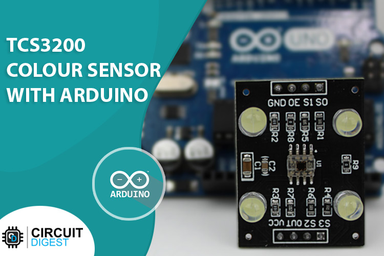
A color sensor is a simple, and easy-to-use device that can be used to identify the color of an object and after detecting the color, appropriate action can be triggered. This type of sensor provides easy solutions for sorting and packaging in an industrial environment while expensive sensors are used in industries, the economical ones such as TCS3200 can be used for less demanding DIY Applications. So in this article, we thought to interface a TCS3200 color sensor with an Arduino and in the process, you will know about the details of this sensor and its working. So without further ado, let's get right into it.
TCS3200 Color Sensor Pinout
The TCS3200 Color Sensor module has 8 pins; those are VCC, OUT, S3, S2, S1, S0, OUT, 0E, and GND. All the pins of this sensor module are digital, except VCC and Ground. The Pinout of a TCS3200 Color Sensor is shown below:
VCC is the power supply pin of the color sensor that can be connected to 5V or 3.3V of the supply.
S0 and S1 The S0 and S1 pins can be used to select the Output Frequency Scaling Percentage of the sensor. By configuring these pins it can be set to 2%, 20%, or 100% scaling.
S2 and S3 The S2 & S3 pins can be used to select the color array of the sensor. By selecting the right color array one after the other, this sensor identifies a color.
OE This is the Output Enable or Disable pin of the color sensor module. This pin is pulled down on the module board to disable the sensor by giving a high pulse to this pin.
OUT This is the output pin of the sensor, when a particular color is detected by the sensor, the output pulse frequency on this pin changes, by detecting this change in pulse width we can determine the color.
Ground is the ground pin of the Color Sensor module and it should be connected to the ground pin of the Arduino.
How Does a Color Sensor Module Work?
The color sensor uses a very basic principle of light to identify the color. You see white is made up of three primary colors which are Red, Green and Blue and each has different wavelengths. When light falls on a surface, depending on the material properties, it gets absorbed or reflected. That reflected light gets picked up by our eye and as a result, we can see colors.

Now let's look at how the TCS3200 color sensor works, as you can see in the gif above, we have the color sensor and we are giving High and low signals to the S0 and S1 pins of the sensor module which sets the sensor to 20% frequency scaling. That means the sensor will operate at a 200 KHz frequency. In this mode, the duty cycle of the sensor will remain at 50% but the output frequency of the sensor will change according to the color value. The S2 and S3 pins are used to select the array of photodiodes and as you can see in the gif for each color that is visible to the sensor we will set the array to red green and blue filter one by one. If the color detected by the sensor matches the selected array of the sensor, the output frequency of the sensor will increase and for any other situations the output frequency mostly stays the same or you can see a minute variation in the output frequency. For more details, you can check out the datasheet of the TCS3200 Color Sensor IC. As we have mentioned earlier the S0, S1, S2, and S3 pins are used to configure the sensor in the below table we have described just that.
S0 and S1 Sets Output Frequency Scaling Factor:
S0 | S1 | Output Frequency Scaling Factor |
L | L | Power down mode |
L | H | Scaling Factor 2% |
H | L | Scaling Factor 20% |
H | H | Scaling Factor 100% |
S2 and S3 Sets the Internal Filter Type:
S2 | S3 | Output Frequency Scaling Factor |
L | L | Red Filter |
L | H | Blue Filter |
H | L | Clear (No Filter) |
H | H | Green Filter |
TCS3200 Color Sensor Module – Parts
This is a cheap and easy to use sensor that can be used for many different applications. This sensor identifies the color and puts the result out in the digital format. The parts marking of the TCS3200 colour sensor is shown below.

At the heart of the sensor, you can find the TS3200 Color Sensor IC, this is very inexpensive and easy to use, designed and developed by TAOS (Texas Advanced Optoelectronic Solutions Inc). There are also four white LEDs, these LEDs light up when the module powers on. These LEDs light up the object that the sensor needs to sense. Other than that, there is a filter capacitor, a decoupling capacitor and some resistors onboard. The operating voltage of this module is 2.7V to 5.5V.
Commonly Asked Questions about Color Sensor TCS3200
What does a color sensor detect?
A color sensor can detect the received light intensity for red, blue, and green respectively, making it possible to determine the color of the target object.
How many pins are there in the color sensor?
It consists of color filters, photodiode array, current to frequency converter and final square wave output which can be given directly to a microcontroller. The TSC3200 Color Sensor IC is an 8 pin IC with SOC package. The following image shows the pin diagram of the Colou Sensor IC.
Do color sensors work in the dark?
Yes, it can work in the dark because it has four white bright LEDs.The color sensor can distinguish between colors or measure the intensity of the reflected light, making it ideal for line following. By emitting its own light, the sensor can work even in absolute darkness to determine the color or brightness of the surface.
What are the main parts of a color sensor?
Color sensors contain a white light emitter to illuminate the surface. Three filters with wavelength sensitivities at 580 nm, 540 nm, and 450nm to measure the wavelengths of red, green and blue colors respectively.
Circuit Diagram of TCS3200 Color Sensor Module
The Circuit Diagram of the TCS3200 Color Sensor is shown below and it's very simple and easy to understand.

In the schematic diagram, you can see the TCS3200 IC in the heart of the circuit and since the out pin of the IC has low impedance there is a 1K resistor in series with the IC. Also, you can see that there are 4 LEDs with a 330R current limiting resistor. You can also see the two 10K pull-up resistors that are pulling up the S0 and S1 pins of the IC. On the board, there is a 10uF filter capacitor and a 100nf decoupling capacitor. Other than that, we have two 0 ohms resistors as jumper links.
TCS3200 Color Sensor with Arduino UNO – Connection Diagram
Now that we have completely understood how a TCS3200 color Sensor works, we can connect all the required wires to Arduino and write the code to get all the data out from the sensor. The Connection Diagram of the TCS3200 with Arduino is shown below-

Connecting the TCS3200 sensor with the Arduino is very simple. To communicate with the sensor we don't need anything other than five GPIO pins of the Arduino, and that is why we have used GPIO 8,7,6,5,4 pins of the Arduino. Finally, to power the sensor we have used the 5V and Ground pins of the Arduino Board.

Arduino Code for Interfacing TCS3200 Color Sensor Module with Arduino
The code to process data from the TCS3200 Sensor is very simple and easy to understand. We just need to define the pins through which the sensor is connected with the Arduino. Once we do that, we will set the different modes of the sensor as mentioned in the datasheet of the device. If everything works correctly the sensor will output the color data in the form of pulses. We will use the pulsein() function of the Arduino to measure the pulse duration and determine the colors.
We will initialise our code by defining the sensor through which we will configure the sensor and process the data out of the sensor.
/*
 *  Sensor Pin S0 -> Arduino Pin D8
 *  Sensor Pin S1 -> Arduino Pin D7
 *  Sensor Pin S2 -> Arduino Pin D6
 *  Sensor Pin S3 -> Arduino Pin D5
 *  Sensor Pin OUT -> Arduino Pin D4
*/
#define S0_PIN 8
#define S1_PIN 7
#define S2_PIN 6
#define S3_PIN 5
#define OUT_PIN  4
Next, we have our setup() function. In the setup function, we will set the S0, S1, S2, and S3 pin as Output and OUT_Pin as input.
// Set the S0, S1, S2, S3 Pins as Output
  pinMode(S0_PIN, OUTPUT);
  pinMode(S1_PIN, OUTPUT);
  pinMode(S2_PIN, OUTPUT);
  pinMode(S3_PIN, OUTPUT);
 //Set OUT_PIN as Input
  pinMode(OUT_PIN, INPUT);
Next in the setup function, we set the S0 Pin high and the S1 Pin low, this will scale the scaling factor to 20% which is recommended by the datasheet. We also enable the UART for debugging.
  // Set Pulse Width scaling to 20%
  digitalWrite(S0_PIN, HIGH);
  digitalWrite(S1_PIN, LOW);
// Enable UART for Debugging
  Serial.begin(9600);
Next, we have our loop function; in the loop function, we declare three local variables named r, g, and b. These variables will hold the RGB values given off by the sensor. After that, we made three functions to process the Red, Green, and Blue Values. And store these values in r, g, and b variables. We also add some delay of 200ms to give the sensor time to process the data. Once the data acquisition process is finished, we print the values in the serial monitor window. We also have three if statements with three magic values. These values are chosen after placing the object several times in front of the sensor and averaging the output values. If this value matches the sensor's output value, then you will get the name of that color in the serial monitor window.
void loop()
{
  int r, g, b;
  r = process_red_value();
  delay(200);
  g = process_green_value();
  delay(200);
  b = process_blue_value();
  delay(200);
  Serial.print("r = ");
  Serial.print(r);
  Serial.print(" ");
  Serial.print("g = ");
  Serial.print(g);
  Serial.print(" ");
  Serial.print("b = ");
  Serial.print(b);
  Serial.print(" ");
  Serial.println();
  if (r < 42)
  {
    Serial.println("Colour Pink");
  }
  else if (g < 63)
  {
    Serial.println("Colour Green");
  }
  else if (r < 64)
  {
    Serial.println("Colour Red");
  }
}
This marks the end of our loop function, now let's talk about the functions that process the output data from the sensor and return the value in integer format. These three functions are exactly the same; the only difference is how the S2 and S3 pin of the sensor is configured. To process the red color, both S2 and S3 pins should be low. To process green color, S2 and S3 pins should be high. And to process blue color S2 should be low and S3 should be high. As we have mentioned earlier the pulseIn() function is used to determine the pulse width of the sensor. The function returns the value in milliseconds and we are simply printing that value in the serial monitor window.
int process_red_value()
{
  digitalWrite(S2_PIN, LOW);
  digitalWrite(S3_PIN, LOW);
  int pulse_length = pulseIn(OUT_PIN, LOW);
  return pulse_length;
}
int process_green_value()
{
  digitalWrite(S2_PIN, HIGH);
  digitalWrite(S3_PIN, HIGH);
  int pulse_length = pulseIn(OUT_PIN, LOW);
  return pulse_length;
}
int process_blue_value()
{
  digitalWrite(S2_PIN, LOW);
  digitalWrite(S3_PIN, HIGH);
  int pulse_length = pulseIn(OUT_PIN, LOW);
  return pulse_length;
}
This marks the end of our code section and we can move to another section of the code.
Working of the TCS3200 Color Sensor Module
The gif below shows the hardware circuitry of the TCS3200 color sensor with Arduino in action. On the left-hand side of the GIF, we have our Arduino that is connected with the sensor according to the schematic shown in the above section. Now what we are going to do is we are going to place a red, green, and blue object in front of the sensor and we observe the serial monitor to check if the sensor can recognize the color or not.
And as you can see in the serial monitor window, the sensor successfully distinguished three colors.
TCS3200 Color Sensor not Working?- Here is what you should do
If you are having trouble reading the TCS3200 sensor, please first check the operating voltage of the device. The stable operating voltage of this device is 2.7V to 5.5V. Driving the sensor with any other voltage values will make the sensor unstable.
If you are having fluctuations in the reading try covering up the sensor with a box. This will keep the distance of the sensor constant and also it will reduce the outside noise.
If you are having scaling issues, please check the S0 and S1 pins of the sensor if they are configured correctly.
If you are having issues with the output, please make sure that the S2 and S3 pins are configured properly.
Projects using Color Sensor
DIY Arduino Based Color Sorter Machine
If you are looking for an interesting project on the internet, then this may be the project that you are looking for. Because in this project we have used the TCS3200 color sensor and the Arduino to build a color sorting machine that was able to efficiently short our candies for us.
If you are looking for a currency counting machine then this project is what you are looking for. Because in this project we are using an Arduino and a TCS3200 color sensor module to build a machine that is able to count our currency for us.
Detecting Colors using Raspberry Pi
If you are interested in interfacing the TCS3200 Color sensor with Raspberry Pi then this project is for you because in this project we are using the TCS3200 color sensor and a Raspberry Pi.
Supporting Files
Complete Project Code
/*
    Sensor Pin S0 -> Arduino Pin D8
    Sensor Pin S1 -> Arduino Pin D7
    Sensor Pin S2 -> Arduino Pin D6
    Sensor Pin S3 -> Arduino Pin D5
    Sensor Pin OUT -> Arduino Pin D4
*/
#define S0_PIN 5
#define S1_PIN 4
#define S2_PIN 7
#define S3_PIN 6
#define OUT_PIN  8
void setup()
{
  // Set the S0, S1, S2, S3 Pins as Output
  pinMode(S0_PIN, OUTPUT);
  pinMode(S1_PIN, OUTPUT);
  pinMode(S2_PIN, OUTPUT);
  pinMode(S3_PIN, OUTPUT);
  //Set OUT_PIN as Input
  pinMode(OUT_PIN, INPUT);
  // Set Pulse Width scaling to 20%
  digitalWrite(S0_PIN, HIGH);
  digitalWrite(S1_PIN, LOW);
  // Enabl UART for Debugging
  Serial.begin(9600);
}
void loop()
{
  int r, g, b;
  r = process_red_value();
  delay(200);
  g = process_green_value();
  delay(200);
  b = process_blue_value();
  delay(200);
  Serial.print("r = ");
  Serial.print(r);
  Serial.print(" ");
  Serial.print("g = ");
  Serial.print(g);
  Serial.print(" ");
  Serial.print("b = ");
  Serial.print(b);
  Serial.print(" ");
  Serial.println();
  if (r < 42)
  {
    Serial.println("Colour Pink");
  }
  else if (g < 63)
  {
    Serial.println("Colour Green");
  }
  else if (r < 64)
  {
    Serial.println("Colour Red");
  }
}
int process_red_value()
{
  digitalWrite(S2_PIN, LOW);
  digitalWrite(S3_PIN, LOW);
  int pulse_length = pulseIn(OUT_PIN, LOW);
  return pulse_length;
}
int process_green_value()
{
  digitalWrite(S2_PIN, HIGH);
  digitalWrite(S3_PIN, HIGH);
  int pulse_length = pulseIn(OUT_PIN, LOW);
  return pulse_length;
}
int process_blue_value()
{
  digitalWrite(S2_PIN, LOW);
  digitalWrite(S3_PIN, HIGH);
  int pulse_length = pulseIn(OUT_PIN, LOW);
  return pulse_length;
}


