

Want to give your project a sense of sound! Then follow along because in this project, we are interfacing a sound sensor to build some interesting projects with it. The KY-038 sound sensor we are using uses a condenser-type microphone to detect sound waves, which gives us a perfect balance of stability and reliability. So in this article, we decided to interface a KY-038 sensor with ESP32 and build a simple decibel meter out of it. In the process, we will let you know how a sound sensor works, how to work with it, and the pros and cons of it, so without further ado, let's get right into it. With a few tweaks, this circuit can also be converted into a Noise pollution detector, a burglar alarm, etc.
The KY-038 sound sensor module is a widely used sound detection sensor with ESP32 microcontrollers. This sensor, which uses a condenser microphone, is very stable and reliable when building decibel meters, noise detectors, and sound-activated switches. This guide will teach both ESP32 sound sensor programming and KY-038 sound sensor pinout details while also taking you through a working decibel meter project with a full ESP32 sound sensor wiring diagram.
Table of Contents
- What is the KY-038 Sound Sensor Module?
- └ Specifications
- Pinout Configuration
- How Does the KY-038 Microphone Sound Sensor Module Work?
- Sound Sensor Module – Parts
- Sound Sensor Wiring Diagram
- └ KY-038 to ESP32 Connections
- Circuit Diagram
- Programming Guide
- Complete Arduino Code
- GitHub Repository
- Conclusion
- └ Key Takeaways
What is the KY-038 Sound Sensor Module?
The KY-038 sound sensor module is a sound detection sensor that detects sound waves from a high-sensitivity condenser microphone and converts sound into electrical signals. This microphone sound sensor module has analog and digital outputs, making it an adaptable solution for a number of sound detection applications, including burglar alarms, noise pollution monitoring, and voice-activated systems.
KY-038 Sound Sensor Specifications
| Parameter | Specification |
| Operating Voltage | 3.3V - 5V DC |
| Operating Current | 4-5mA |
| Detection Range | 100dB at 3-6 kHz |
| Microphone Type | Electret Condenser |
| Output Type | Analog (AOUT) & Digital (DOUT) |
| Comparator IC | LM393 |
| Dimensions | 32mm x 17mm |
KY-038 Sound Sensor Pinout Configuration
The KY-038 sound sensor pinout has 4 pins: VCC, GND, Digital Out, and Analog Out. We can either use the AO pin as an output for analog reading or the DO pin as an output for digital readout. The Sound sensor pinout is as follows:
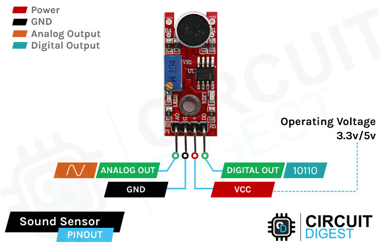
VCC is the power supply pin of the Sound Sensor that can be connected to 3.3V or 5V of the supply. But note that the analog output will vary depending on the provided supply voltage.
GND is the ground pin of the Sound Sensor module, and it should be connected to the ground pin of the Arduino.
DOUT is the Digital output pin of the board; a low output indicates that no sound is detected by the sensor, and a high output indicates that the sensor has detected sound.
AOUT is the Analog output pin of the board that will give us an analog reading directly from the Sound sensor.
How Does the KY-038 Microphone Sound Sensor Module Work?
The working of the KY-038 sound sensor is very simple; the main component in this module is a condenser microphone. The microphone gives out only analog signals when a sound wave hits the diaphragm of the sensor. This analog signal gets processed by the op-amp, and we get the digital output.
The main component of a sound sensor is a microphone. There are many different types of microphones, like Carbon Microphones, Fibre Optic Microphones, Ribbon Microphones, and Laser Microphones, but the sound sensor module we are using has a condenser microphone. An image of the sound sensor module is shown below.
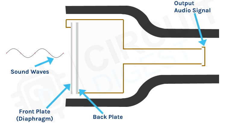
The KY-038 microphone sound sensor module consists of an electret condenser microphone, which is made up of two charged metal plates.
∗ Diaphragm (Front Plate): A very thin, flexible material that moves and vibrates when a sound pressure wave strikes it
∗ Backplate (Fixed Plate): An electrode that is not flexible and that stays charged
∗ Capacitor: The two plates together are a variable capacitor; changing the distance means changing the voltage
∗ Signal Conditioning: The LM393 op-amp amplifies the weak output signal for analog output and compares the digital level to a set threshold.
As you can see from the image, a condenser microphone consists of two charged metal plates. The first plate is called the diaphragm, and the second plate is the backplate of the microphone. These two plates together form a capacitor. When a sound wave hits the diaphragm of the microphone, the diaphragm starts to vibrate, and the distance between the two plates changes. The movement of the diaphragm and the change in spacing produce the electrical signal that corresponds to the sound picked up by the microphone, and this signal then gets processed by the onboard op-amp. This module also has two built-in onboard LEDs, one of which lights up when power is applied to the board, and the other one lights up when the incoming audio signal exceeds the threshold value set by the potentiometer.
We previously used a sound sensor with Arduino to build an Arduino Whistle Detector, an Arduino-based musical fountain and a noise level meter.
Sound Sensor Module – Parts
For many different projects, this can be used to build sound-reactive switches or to build a sound-reactive LED visualizer. This is why this sensor is popular among beginners, as these are low-power, low-cost, rugged, and feature a wide sensing range that can be trimmed down to adjust the sensitivity.
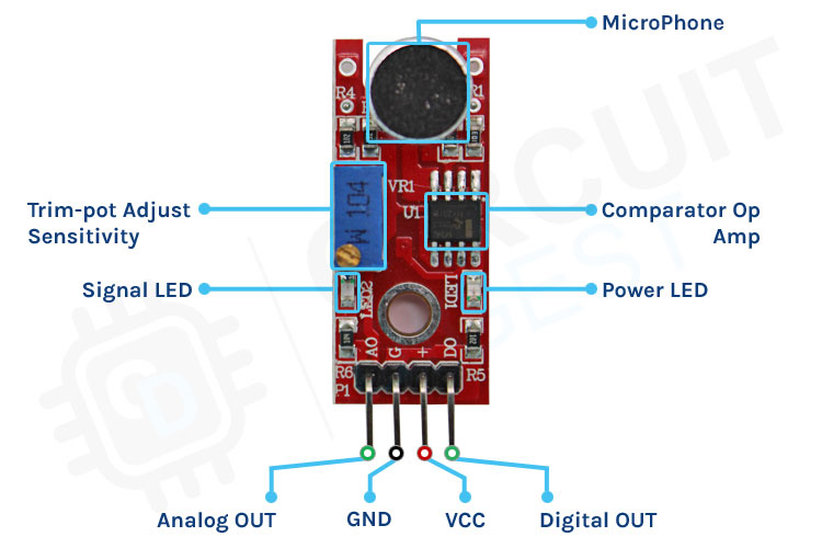
This sensor has three pins, two of which are power pins, levelled VCC and GND, and the other two are analog and digital pins shown in the diagram above. It has an onboard power LED and a signal LED. The power LED turns on when power is applied to the board, and the signal LED turns on when the circuit is triggered. This board also has a comparator Op-amp that is responsible for converting the incoming analog signal to a digital signal. We also have a sensitivity adjustment potentiometer; with that, we can adjust the sensitivity of the device. Last, we have the condenser microphone that is used to detect sound. All these together make the total Sound Sensor Module.
| Component | Description |
|---|---|
| Electret Condenser Microphone | High-sensitivity sound transducer (marked as MIC on PCB) |
| LM393 Comparator | Dual op-amp IC used for analog amplification and digital threshold detection |
| Sensitivity Potentiometer | 10kΩ variable resistor for adjusting the digital output trigger threshold |
| Power LED (Red) | Indicates that the module is receiving power |
| Signal LED (Green) | Lights up when sound exceeds the set threshold (digital mode) |
| Supporting Components | Resistors and capacitors for signal filtering and circuit stability |
Commonly Asked Questions about Sound Sensor Module
⇥ What are the types of sound sensors?
There are different types of microphones that are known as sound sensors, like dynamic, condenser, ribbon, carbon, etc.
⇥ What are the advantages of a sound sensor?
Sound sensors can be used for security systems; often, they work with speech recognition software where sound or speech is converted to text. This is a faster approach compared to typing using a keyboard.
⇥ What is the range of the sound sensor?
This sensor is capable of determining noise levels within 100 dB or decibels at 3 kHz and 6 kHz frequencies, approximately.
⇥ Can Arduino detect sound?
You'll learn how to use the KY-038 sound detection sensor with Arduino. You can measure changes in the intensity of sound in an environment with the ADC of the Arduino.
⇥ In what way do KY-038 and KY-037 sound sensor modules differ from each other?
KY-037 sound sensor module is a larger sound sensor module with the same functionality but different PCB/Pad layout and component placement. The KY-038 sound sensor module has a smaller size, employs the same LM393 comparator with a condenser microphone, but is optimised in the circuitry to reject noise better. Both modules feature analog and digital outputs, which can be set to a regional threshold using an onboard wire potentiometer.
⇥ Can I use the KY-038 sound sensor with Raspberry Pi and other microcontrollers?
Yes, the KY-038 microphone sound has no problem connecting to any microcontroller that has an ADC interface. For Raspberry Pi, use the digital output (DOUT) interface with GPIO or plug in an external ADC like the MCP3008 to Analog in, since RPi does not have an ADC interface. The KY-038 is suitable for Arduino, ESP8266, STM32, PIC and all type of Micro controller 3.3V/5V
⇥ What do I need for prompt calibration of the KY-038 sound sensor for decibel reading?
For quick calibration, you will need a reference sound level meter. Produce [60dB, 80dB and 90dB] sound levels, and their corresponding ADC values can be tallied. Align or match your code's map() function parameters to these reference points. This is to indicate the penetrating sound level in relation to the threshold set on the onboard potentiometer switch. The potentiometer is simply set for adjusting the digital threshold, but the analog output used for calibrating the decibel reading cannot, of course, really benefit from it. A-weighting filters will need to be accounted, as well as frequency response.
⇥ What is the highest detectable range of KY-038 sound sensor?
KY-038 sound sensor detects up to 100 dB at the frequency range 3-6 kHz with best sensitivity. Detection distance varies based on intensity of sound source: loud claps are detected up to 3-5 meters, everyday conversation at 1-2 meters. Sensitivity drops dramatically above 10 kHz and below 100 Hz because of microphone capsule frequency response characteristics.
ESP32 Sound Sensor Wiring Diagram
The schematic diagram for the Sound Sensor module is shown below. The schematic itself is very simple and needs a handful of generic components to build. If you don't have a prebuilt module on hand but still want to test your project, the schematic below will come in handy. To connect the sound sensor ESP32, you only need three basic wires to carry out basic sound detection. The sound sensor connection diagram below illustrates the connection of the KY-038 module and ESP32 to obtain analog readings with the integrated ADC (Analog to Digital Converter).
KY-038 to ESP32 Connections
| KY-038 Pin | ESP32 Pin | Purpose |
| VCC | 3.3V | Power supply (use 3.3V for accurate ADC readings) |
| GND | GND | Common ground reference |
| AOUT | GPIO35 | Analog signal input (ADC1_CH7) |
| DOUT | Any GPIO (optional) | Digital threshold detection |
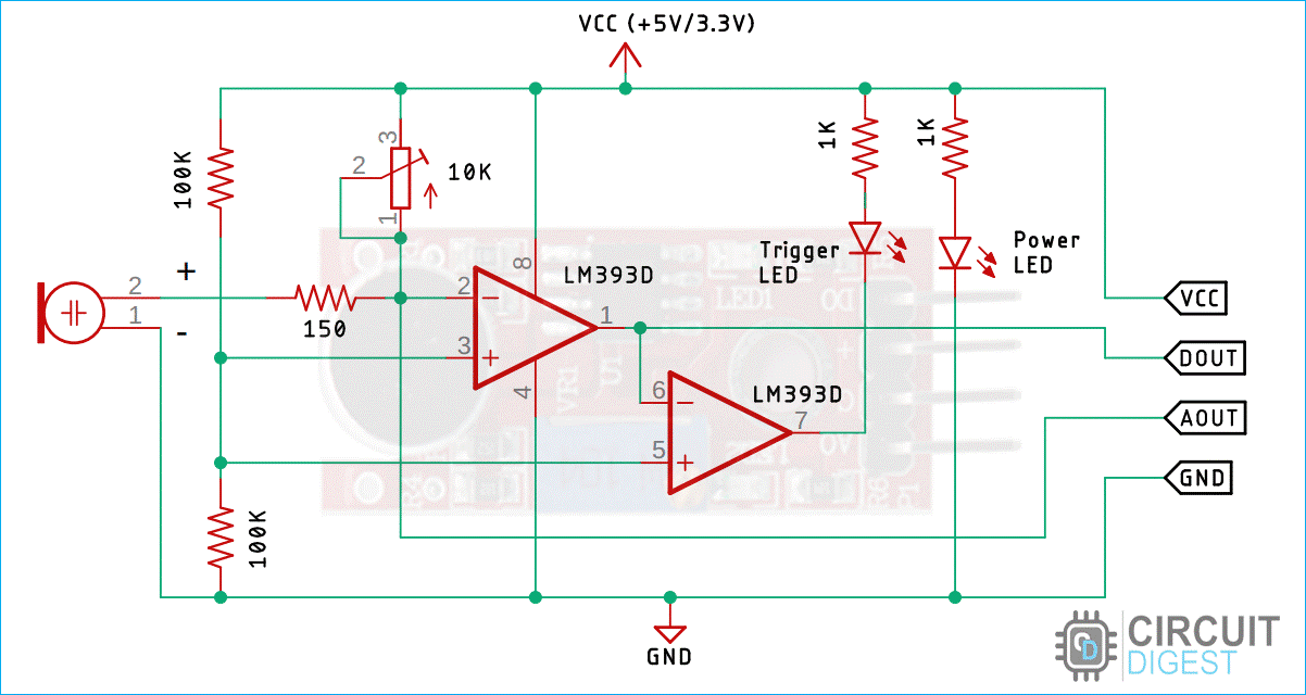
In the schematic, we have an LM393 op-amp that is a low-power, low-cost, low-offset voltage op-amp that can be powered from a 3.3V or 5V supply. Please note that the analog output voltage of the device will depend on the supply voltage of the device. The main job of this op-amp is to convert the incoming analog signal from the sensor probe to a digital signal. There is also this 10K potentiometer that is used to set a reference voltage for the op-amp; also this potentiometer is used to generate the reference voltage for the analog out function of the module.
If the input voltage of the sensor goes below the threshold voltage set by the potentiometer, the output of the op-map goes low. Other than that, we have two LEDs. The first one is a power LED, and the other one is the trigger LED. The power LED turns on when power is applied to the board, and the trigger LED turns on when a certain threshold is reached. This is how this basic circuit works.
Circuit Diagram for Decibel Meter with Sound Sensor and ESP32
Now that we have a good understanding of how the sound sensor works, we can connect all the required wires to the Arduino as per the schematic shown below.
To connect the sound sensor ESP32, you only need three basic wires to carry out basic sound detection. The sound sensor connection diagram below illustrates the connection of the KY-038 module and ESP32 to obtain analog readings with the integrated ADC (Analog to Digital Converter).

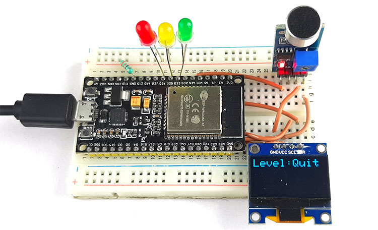
Connecting the sound sensor to the microcontroller is simple; we just need to power the module with 3.3V power and connect the analog out pin to the ESP32. Now we can process the signal with the ADC of the ESP32. We have also connected three LEDs to show the intensity of the device, and we are also showing the recorded decibel on the OLED display. The LEDs are connected to the GPIO pins of the ESP32, and the OLED module is connected to the I2C pins of the ESP32 device. Learn more about interfacing OLED with ESP32 here.
ESP32 Sound Sensor Programming Guide
ESP32 sound sensor programming includes reading Analog values from the ADC (Analog to Digital Converter) chip, taking samples over specific time windows, and converting peak-to-peak voltage changes to the decibel scale. This code is based on professional techniques for sound level monitoring.
Required Libraries in Arduino
Before uploading your code, you will need to install the corresponding libraries by navigating through the Arduino IDE Library Manager (Sketch → Include Library → Manage Libraries)
- Wire.h - The built-in I2C communication library
- Adafruit_GFX.h - Core graphics library for displays
- Adafruit_SSD1306.h - Display driver for the SSD1306 OLED screen.
Complete Arduino Code for ESP32 Decibel Meter
This optimised code reads sound levels from the KY-038 sound sensor, calculates decibel values, and displays results on an OLED screen with LED indicators for different noise levels.
The code for the Arduino-based decibel meter is very simple and easy to understand. In the code, we will just measure the audio noise coming from the microphone and convert it to a digital signal with an ADC sample and figure out the decibel noise.
We start our code, including all the required libraries; those are Wire.h, Adafruit_GFX.h, and Adafruit_SSD1306.h library. Next, we will define the screen width and screen height.
#include <Wire.h>
#include <Adafruit_GFX.h>
#include <Adafruit_SSD1306.h>
#define  SCREEN_WIDTH 128 // OLED display width, in pixels
#define  SCREEN_HEIGHT 64 // OLED display height, in pixels
#define  OLED_RESET   -1 // Reset pin # (or -1 if sharing Arduino reset pin)
Next, we have defined the instance for the Adafruit_SSD1306 library, which is displayed.
Adafruit_SSD1306 display(SCREEN_WIDTH, SCREEN_HEIGHT, &Wire, OLED_RESET);Next, we have two variables to hold sampled data from the ADC.
const int sampleWindow = 50;
unsigned int sample;
We have defined all the required input and output pins for the LEDs and the sound sensor.
#define SENSOR_PIN 35
#define PIN_QUIET 33
#define PIN_MODERATE 25
#define PIN_LOUD 26
Next, we have our setup() function. In the setup function, we set all the required pins as input and output. And we also set the LED pins to low and initialise the serial. Finally, in the setup function, we initialise the display and set it to low.
void setup(){
  pinMode(SENSOR_PIN, INPUT); // Set the signal pin as input
  pinMode(PIN_QUIET, OUTPUT);
  pinMode(PIN_MODERATE, OUTPUT);
  pinMode(PIN_LOUD, OUTPUT);
  digitalWrite(PIN_QUIET, LOW);
  digitalWrite(PIN_MODERATE, LOW);
  digitalWrite(PIN_LOUD, LOW);
  Serial.begin(115200);
  if (!display.begin(SSD1306_SWITCHCAPVCC, 0x3C)) {
    Serial.println(F("SSD1306 allocation failed"));
    for (;;); // Don't proceed, loop forever
  }
  display.clearDisplay();
  display.setTextSize(2);
  display.setTextColor(WHITE);
  display.display();
  digitalWrite(PIN_LOUD, LOW);
}
Then, we have our loop function, in the loop function, we read the data from the ADC and sample it to store it within the min and max variables.
unsigned long startMillis = millis();                  // Start of sample window
  float peakToPeak = 0;                                  // peak-to-peak level
  unsigned int signalMax = 0;                            //minimum value
  unsigned int signalMin = 1024;                         //maximum value
  // collect data for 50 mS
  while (millis() - startMillis < sampleWindow) {
    sample = analogRead(SENSOR_PIN);
    if (sample < 1024) {
      if (sample > signalMax) {
        signalMax = sample;
      }
      else if (sample < signalMin)  {
        signalMin = sample;
      }
    }
  }
Now, to figure out the peak-to-peak signal ratio, we subtract the minimum value from the maximum value and map this value to a 49dB to 90dB signal.
  peakToPeak = signalMax - signalMin;
  int db = map(peakToPeak, 0, 900, 49, 90);
  Serial.print("\t");
  Serial.println(db);
  display.setCursor(0, 0);
  display.print("Loudness: ");
  display.print(db);
  display.print("dB");
  digitalWrite(PIN_LOUD, LOW);
Now, with the help of if statements, we check the values and, according to the values, we light up an LED to show the sound intensity and finally print it on the display.
   else if (db > 60 && db < 85) {
    display.clearDisplay();
    display.setCursor(0, 1);
    display.print("Level:Moderate");
    display.display();
    digitalWrite(PIN_QUIET, LOW);
    digitalWrite(PIN_MODERATE, HIGH);
    digitalWrite(PIN_LOUD, LOW);
  }
  else if (db >= 85 && db <= 90) {
    display.clearDisplay();
    display.setCursor(0, 1);
    display.print("Level:High");
    display.display();
    digitalWrite(PIN_QUIET, LOW);
    digitalWrite(PIN_MODERATE, LOW);
    digitalWrite(PIN_LOUD, HIGH);
  }
  else {
    digitalWrite(PIN_QUIET, LOW);
    digitalWrite(PIN_MODERATE, LOW);
    digitalWrite(PIN_LOUD, LOW);
  }
  delay(200);
}
Technical Summary and GitHub Repository
A technical summary highlights the key objectives, workflow, and outcomes of a project, whereas the GitHub repository serves as a central hub for source code, documentation, and collaboration. Together, they provide both insight and practical access to the project.


Conclusion
The KY-038 sound sensor module, combined with the ESP32, provides an accessible entry point into audio-based electronics projects. By following this ESP32 sound sensor wiring diagram and programming guide, you now have the complete knowledge to implement professional-quality sound detection in your projects.
Key Takeaways:
∗ KY-038 employs condenser microphone technology that accurately picks up sound levels of up to 100dB.
∗ Both the digital and analog outputs provide a good feel, and this is great for many applications!
∗ The ESP32's ADC 12-bit resolution offers good decibel level accuracy measurement.
∗ Peak-to-peak sampling over time periods allows for accurate sound level reading.
∗ The sample will be accurate only if it has been calibrated and the environmental conditions have been taken into consideration.
∗ The module does not consume a lot of power, which is an advantage for battery-powered IoT applications.
Discover Exciting Projects in a Similar Realm
If you are interested in building more such projects, check out our collection of Arduino Projects. We have more than 500 projects with Code and Circuit diagrams that you can use to build your projects today.

Simple Soil Moisture Detector Circuit
Build your own soil moisture sensor with an easy-to-follow circuit. In this project, we are going to build a Transistor Based Simple Soil Moisture Detector Circuit. In this circuit, we have used an NPN transistor to detect soil moisture.

Arduino-based Automatic Plant Irrigation System with Message Alert
Learn to create an automatic plant watering system using Arduino and get text message alerts using the Sim800L module. You'll also set up a 16x2 LCD display for feedback.

Low Power IoT-Based Compact Soil Moisture Monitoring Device
Make your own battery-powered smart soil moisture sensor using IoT technology, focusing on the ESP8266 module as the main controller.

Arduino Smart Irrigation System Using ESP32 and Blynk App
Explore a smart irrigation setup with Arduino and ESP32. This project goes beyond soil moisture sensing, incorporating water level, humidity, and temperature sensors. Discover how to use IoT features with Blynk.
Complete Project Code
#include <Wire.h>
#include <Adafruit_GFX.h>
#include <Adafruit_SSD1306.h>
#define  SCREEN_WIDTH 128 // OLED display width, in pixels
#define  SCREEN_HEIGHT 64 // OLED display height, in pixels
#define  OLED_RESET   -1 // Reset pin # (or -1 if sharing Arduino reset pin)

Adafruit_SSD1306 display(SCREEN_WIDTH, SCREEN_HEIGHT, &Wire, OLED_RESET);

const int sampleWindow = 50;
unsigned int sample;

#define SENSOR_PIN 35
#define PIN_QUIET 33
#define PIN_MODERATE 25
#define PIN_LOUD 26

void setup(){
  pinMode(SENSOR_PIN, INPUT);
  pinMode(PIN_QUIET, OUTPUT);
  pinMode(PIN_MODERATE, OUTPUT);
  pinMode(PIN_LOUD, OUTPUT);

  digitalWrite(PIN_QUIET, LOW);
  digitalWrite(PIN_MODERATE, LOW);
  digitalWrite(PIN_LOUD, LOW);

  Serial.begin(115200);

  if (!display.begin(SSD1306_SWITCHCAPVCC, 0x3C)) {
    Serial.println(F("SSD1306 allocation failed"));
    for (;;);
  }

  display.clearDisplay();
  display.setTextSize(2);
  display.setTextColor(WHITE);
  display.display();
  digitalWrite(PIN_LOUD, LOW);
}

void loop()
{
  unsigned long startMillis = millis();
  float peakToPeak = 0;

  unsigned int signalMax = 0;
  unsigned int signalMin = 1024;

  // collect data for 50 mS
  while (millis() - startMillis < sampleWindow)
  {
    sample = analogRead(SENSOR_PIN);

    if (sample < 1024)
    {
      if (sample > signalMax)
      {
        signalMax = sample;
      }
      else if (sample < signalMin)
      {
        signalMin = sample;
      }
    }
  }
  peakToPeak = signalMax - signalMin;
  int db = map(peakToPeak, 0, 900, 49, 90);
  Serial.print("\t");
  Serial.println(db);
  display.setCursor(0, 0);
  display.print("Loudness: ");
  display.print(db);
  display.print("dB");
  digitalWrite(PIN_LOUD, LOW);
  if (db <= 55)
  {

    display.clearDisplay();
    display.setCursor(0, 1);
    display.print("Level:Quite");
    display.display();
    digitalWrite(PIN_QUIET, HIGH);
    digitalWrite(PIN_MODERATE, LOW);
    digitalWrite(PIN_LOUD, LOW);
    //  delay(3000);
  }
  else if (db > 60 && db < 85)
  {
    display.clearDisplay();
    display.setCursor(0, 1);
    display.print("Level:Moderate");
    display.display();
    digitalWrite(PIN_QUIET, LOW);
    digitalWrite(PIN_MODERATE, HIGH);
    digitalWrite(PIN_LOUD, LOW);
  }
  else if (db >= 85 && db <= 90)
  {
    display.clearDisplay();
    display.setCursor(0, 1);
    display.print("Level:High");
    display.display();
    digitalWrite(PIN_QUIET, LOW);
    digitalWrite(PIN_MODERATE, LOW);
    digitalWrite(PIN_LOUD, HIGH);
  }
  else
  {
    digitalWrite(PIN_QUIET, LOW);
    digitalWrite(PIN_MODERATE, LOW);
    digitalWrite(PIN_LOUD, LOW);
  }

  delay(200);
}

Hello! I saw your project, it's awesome! but I have some questions.
1. Can esp32 change to esp32-s3? if yes, the pin of the circuit are the same?
2. Can OLED use TFT LCD Touch Panel? if yes, what is the circuit (which pin to which pin)?