
A sound sensor is a simple, easy-to-use, and low-cost device that is used to detect sound waves traveling through the air. Not only this but it can also measure its intensity and most importantly it can convert it to an electrical signal which we can read through a microcontroller. But do you know how this type of sound sensor works? What is it used for? and how to interface a sound sensor with an Arduino? If you have these queries and are looking for answers, then don't worry, we'll answer them all in this article.
Sound Sensor Pinout
The Sound sensor module has 4 pins VCC, GND, Digital Out, and Analog Out. We can either use the AO pin as an output for analog reading or the DO pin as an output for digital readout. The Sound sensor pinout is as follows:
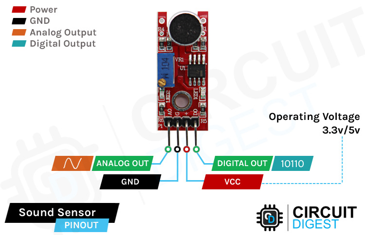
VCCis the power supply pin of the Sound Sensor that can be connected to 3.3V or 5V of the supply. But note that the analog output will vary depending upon the provided supply voltage.
GNDis the ground pin of the Sound Sensor module and it should be connected to the ground pin of the Arduino.
DOUTis the Digital output pin of the board, low output indicates that no sound is detected by the sensor, and high indicates that the sensor has detected sound.
AOUTis the Analog output pin of the board that will give us an analog reading directly from the Sound sensor.
How Does a Sound Sensor Module Work?
The working of the sounds sensor module is very simple and easy to understand, the main component in this module is a condenser microphone. The microphone gives out only analog signals when a sound wave hits the diaphragm of the sensor, this analog signal gets processed by the op-amp and we get the digital output.
The main component of a sound sensor is a microphone. There are many different types of microphones, like Carbon Microphone, Fiber Optic Microphone, Ribbon Microphone, and Laser Microphone, but the sound sensor module we are using has a condenser microphone. An image of the sound sensor module is shown below,
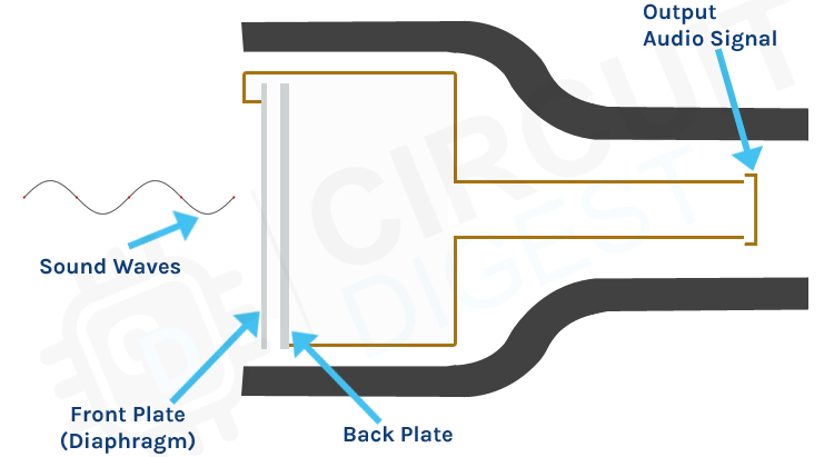
As you can see from the image, a condenser microphone consists of two charged metal plates. The first plate is called the diaphragm and the second plate is the backplate of the microphone. These two plates together form a capacitor. When a sound wave hits the diaphragm of the microphone the diaphragm starts to vibrate, and the distance between the two plates changes. The movement of the diaphragm and the change in spacing produces the electrical signal that corresponds to the sound that's picked up by the microphone and this signal then gets processed by the onboard op-amp. This module also has two built-in onboard LEDs, one of which lights up when power is applied to the board and the other one lights up when the incoming audio signal exceeds the threshold value set by the potentiometer.
Sound Sensor Module – Parts
For many different projects, this can be used to build sound-reactive switches or to build a sound-reactive LED visualizer. This is why this sensor is popular among beginners as these are low power, low cost, rugged, and feature a wide sensing range that can be trimmed down to adjust the sensitivity.
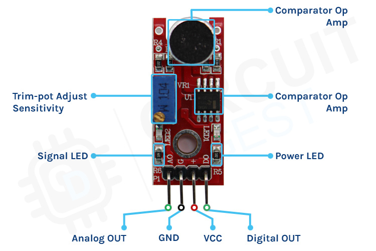
This sensor has three pins, two of which are power pins leveled VCC and GND and the other two pins are analog and digital pins which are shown in the diagram above. It has an onboard power LED and a signal LED. The power LED turns on when power is applied to the board and the signal LED turns on when the circuit is triggered. This board also has a comparator Op-amp that is responsible for converting the incoming analog signal to digital signal. We also have a sensitivity adjustment potentiometer; with that, we can adjust the sensitivity of the device. Last, we have the condenser microphone that is used to detect the sound. All these together make the total Sound Sensor Module.
Commonly Asked Questions about Sound Sensor Module
What are the types of sound sensors?
There are different types of microphones that are known as sound sensors like dynamic, condenser, ribbon, carbon, etc.
What are the advantages of a sound sensor?
Sound sensors can be used for security systems, often it works with speech recognition software where sound or speech is converted to text. This is a faster approach compared to typing using a keyboard.
What is the range of the sound sensor?
This sensor is capable of determining noise levels within 100 dB's or decibels at 3 kHz, 6 kHz frequencies range, approximately.
Can Arduino detect sound?
You'll learn how to use the KY-038 sound detection sensor with Arduino. You can measure changes in the intensity of sound in an environment with the ADC of the Arduino.
Circuit Diagram for Sound Sensor Module
The schematic diagram for the Sound Sensor module is shown below. The schematic itself is very simple and needs a handful of generic components to build. If you don't have a prebuilt module on hand but still want to test your project, the schematic below will come in handy.

In the schematic, we have an LM393 op-amp that is a low-power, low cost, low offset voltage op-amp that can be powered from a 3.3V or 5V supply. Please note that the analog output voltage of the device will depend on the supply voltage of the device. The main job of this op-amp is to convert the incoming analog signal from the sensor probe to a digital signal. There is also this 10K potentiometer that is used to set a reference voltage for the op-amp, also this potentiometer is used to generate the reference voltage for the analog out function of the module.
If the input voltage of the sensor goes below the threshold voltage set by the potentiometer, the output of the op-map goes low. Other than that we have two LEDs. The first one is a power LED and the other one is the trigger LED. The power LED turns on when power is applied to the board and the trigger LED turns on when a certain set threshold is reached. This is how this basic circuit works.
Sound Sensor with Arduino UNO – Connection Diagram
Now that we have a complete understanding of how a Sound sensor works, we can connect all the required wires to Arduino as shown below.
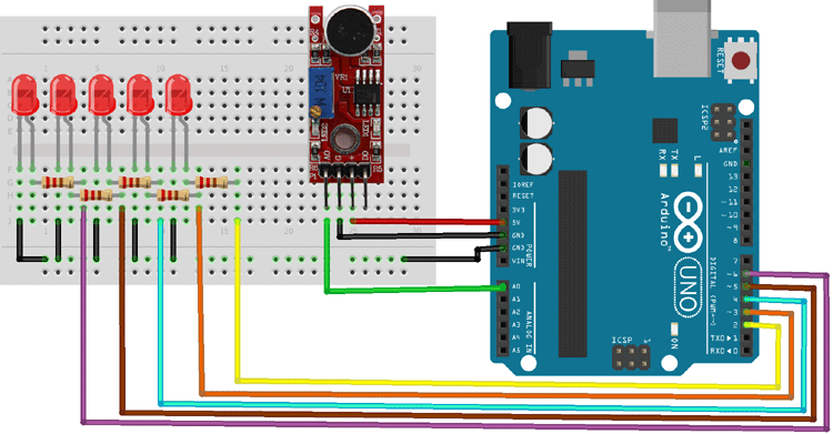
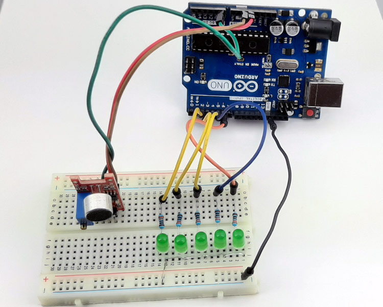
Connecting the Sound Sensor to the microcontroller is really simple. As we all know by now the sensor outputs an analog signal and it's really easy to process the signal. We can use the ADC of the Arduino to process the signal and we can light up some LEDs to show the intensity of the sound received by the microcontroller. The connection of the circuit is also very simple, we have just connected the VCC and ground from the Arduino board to the sensor module and we have used GPIO2 to GPIO6 to connect the LEDs. The ground is common in between LEDS and the Sensor, a hardware image of the setup is shown below,
Arduino Sound Sensor Code
The Arduino Sound Sensor Code is very simple and easy to understand. We are just reading the analog data out of the sensor and lighting up LEDs to visualize the intensity of the sound that is received by the sensor. You can also see that the onboard led on the module lights up when an intense sound reaches the sensor.
We initialize our code by declaring two macros, the First five macros are used to define LEDs and the other pin is the sensorPin through which we are reading the data coming out of the sensor. We also define some other boolean-type variables that will hold the status of the pins.
/* Arduino pins where the LED is attached */
#define LED_1 2
#define LED_2 3
#define LED_3 4
#define LED_4 5
#define LED_5 6
#define sensorPin A0 // Analog input pin that the Sensor is attached to
/* boolean variables to hold the status of the pins*/
bool ledPin1Status;
bool ledPin2Status;
bool ledPin3Status;
bool ledPin4Status;
bool ledPin5Status;
Next, we have our setup() function. In the setup function, we have declared all the led pins as output and the sensor pin as input. We also initialize the serial monitor in the setup function for debugging purposes.
void setup() {
  pinMode(LED_1, OUTPUT);
  pinMode(LED_2, OUTPUT);
  pinMode(LED_3, OUTPUT);
  pinMode(LED_4, OUTPUT);
  pinMode(LED_5, OUTPUT);
  pinMode(sensorPin, INPUT);
  Serial.begin(9600);// initialize serial communications at 9600 bps:
}
Next, we have our loop function. In the loop function, we have a local variable sensorValue in which we are reading the data from the analog pin and storing it for later use. Next we print the data onto the serial monitor window for debugging.
  int sensorValue = analogRead(sensorPin);
  Serial.println(sensorValue);
Next, we have our if statements; in the if statements, we check whether the noise received by the sound sensor is greater than a certain threshold or not. If it is, then we set the status of the boolean variable to 1 otherwise it stays to zero.
  if (sensorValue > 555  )
    ledPin1Status = 1;
  if (sensorValue > 558  )
    ledPin2Status = 1;
  if (sensorValue > 560  )
    ledPin3Status = 1;
  if (sensorValue > 562  )
    ledPin4Status = 1;
  if (sensorValue > 564 )
    ledPin5Status = 1;
Next, we have another if statement, this if statement is necessary because with ADC we don't have interrupt so we cant call an ISR when a certain threshold is reached. The if statement below is there so that we could add a delay to light up the LEDs.
if (ledPin1Status == 1 || ledPin2Status == 1 || ledPin3Status == 1 || ledPin4Status == 1 || ledPin5Status == 1)
Now the whole if statement repeats again but now we light up the corresponding LEDs instead of updating a boolean variable.
 if (sensorValue > 555 || sensorValue < 537  )
      digitalWrite(LED_1, HIGH);
    if (sensorValue > 558 || sensorValue < 534  )
      digitalWrite(LED_2, HIGH);
    if (sensorValue > 560 || sensorValue < 534  )
      digitalWrite(LED_3, HIGH);
    if (sensorValue > 562 || sensorValue < 531 )
      digitalWrite(LED_3, HIGH);
    if (sensorValue > 564 || sensorValue < 528)
      digitalWrite(LED_4, HIGH);
    if (sensorValue > 568 || sensorValue < 525)
      digitalWrite(LED_5, HIGH);
    delay(200);
    ledPin5Status = 0;
    ledPin4Status = 0;
    ledPin3Status = 0;
    ledPin2Status = 0;
    ledPin1Status = 0;
  }
Finally, at the end of the loop, we turn off the LEDs and end our coding process.
digitalWrite(LED_1, LOW);
  digitalWrite(LED_2, LOW);
  digitalWrite(LED_3, LOW);
  digitalWrite(LED_4, LOW);
  digitalWrite(LED_5, LOW);
Working of the Sound Sensor Module
The gif down below shows the Sound Sensor module working. At first, you can see that all 5 LEDs in the breadboard are off but when we tap the board that generates a sound, which lights up some LEDs, and when we tap the board harder all the LEDs light up. If you watch carefully the onboard LED also lights up.
Projects using Arduino and Sound Sensor Module
Previously we have used this sound sensor module to build many interesting projects. If you want to know more about those topics, the links are given below.

Arduino Controlled Musical Fountain
If you are a DIY! enthusiast and you are planning to build something decorative for your home then this project could be for you, because in this project we have used an Arduino and a sound sensor to build a musical fountain that will generate aesthetic design with water.

If you are a beginner and want to build something easy and interesting then this project could be for you, because in this project we have used a condenser microphone and an Arduino to build a simple clap sensitive switch that can turn on and off your appliance with just a clap.

Arduino Whistle Detector Switch
If you want to turn on or off your home appliances with sound then you can build yourself a simple whistle detecting circuit with Arduino and sound sensor. This whistle detecting system reduces the drawbacks of a clap switch and improves reliability of the circuit.

Measure Sound/Noise Level in dB with Arduino
If you looking for an interesting project on the internet and having a hard time finding one then this project could be for you, as because in this project we have used our favorite microcontroller Arduino and a sound sensor to build a decibel meter that can measure sound and so its intensity on the serial monitor window.
Supporting Files


Complete Project Code
/* Arduino pins where the LED is attached*/

#define LED_1 2

#define LED_2 3

#define LED_3 4

#define LED_4 5

#define LED_5 6

#define sensorPin A0 // Analog input pin that the Sensor is attached to

/* boolean variables to hold the status of the pins*/

bool ledPin1Status;

bool ledPin2Status;

bool ledPin3Status;

bool ledPin4Status;

bool ledPin5Status;

void setup() {

  pinMode(LED_1, OUTPUT);

  pinMode(LED_2, OUTPUT);

  pinMode(LED_3, OUTPUT);

  pinMode(LED_4, OUTPUT);

  pinMode(LED_5, OUTPUT);

  pinMode(sensorPin, INPUT);

  Serial.begin(9600);// initialize serial communications at 9600 bps:

}

void loop() {

  int sensorValue = analogRead(sensorPin);

  Serial.println(sensorValue);

  if (sensorValue > 555  )

    ledPin1Status = 1;

   if (sensorValue > 558  )

    ledPin2Status = 1;

   if (sensorValue > 560  )

    ledPin3Status = 1;

   if (sensorValue > 562  )

    ledPin4Status = 1;

   if (sensorValue > 564 )

    ledPin5Status = 1;

  if (ledPin1Status == 1 || ledPin2Status == 1 || ledPin3Status == 1 || ledPin4Status == 1 || ledPin5Status == 1)

  {

    if (sensorValue > 555 || sensorValue < 537  )

      digitalWrite(LED_1, HIGH);

     if (sensorValue > 558 || sensorValue < 534  )

      digitalWrite(LED_2, HIGH);

     if (sensorValue > 560 || sensorValue < 534  )

      digitalWrite(LED_3, HIGH);

     if (sensorValue > 562 || sensorValue < 531 )

      digitalWrite(LED_3, HIGH);

     if (sensorValue > 564 || sensorValue < 528)

      digitalWrite(LED_4, HIGH);

     if (sensorValue > 568 || sensorValue < 525)

      digitalWrite(LED_5, HIGH);

    delay(200);

    ledPin5Status = 0;

    ledPin4Status = 0;

    ledPin3Status = 0;

    ledPin2Status = 0;

    ledPin1Status = 0;

  }

  digitalWrite(LED_1, LOW);

  digitalWrite(LED_2, LOW);

  digitalWrite(LED_3, LOW);

  digitalWrite(LED_4, LOW);

  digitalWrite(LED_5, LOW);

}

It was very practical and useful, thank you.
Please make a project with FFT and how to use it in Arduino using sound sensor.