

Noise pollution has really started to gain importance due to high population density. A normal human ear could hear sound levels from 0dB to 140dB in which sound levels from 120dB to 140dB are considered to be noise. Loudness or sound levels are commonly measured in decibel(dB), we have some instruments which could measure the sound signals in dB but these meters are slightly expensive and sadly we do not have an out of box sensor module to measure sound levels in decibels. And it is not economical to purchase expensive microphones for a small Arduino project which should measure the sound level in a small classroom or living room.
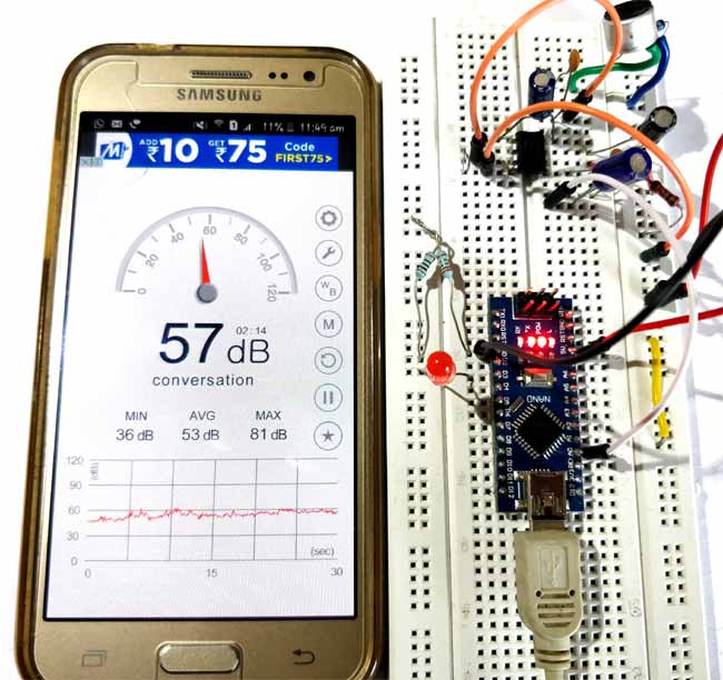
So in this project we will use a normal Electret Condenser microphone with Arduino and try measuring the sound or noise pollution level in dB as close as possible to the actual value. We will use a normal amplifier circuit to amplify the sound signals and feed it to Arduino in which we will use regression method to calculate the sound signals in dB. To check if the values obtained are correct we can use the “Sound Meter” android application, if you have a better meter you can use that for calibration. Do note that this project does not aim to measure dB accurately and will just give values as close as possible to the actual value.
Materials Required:
- Arduino UNO
- Microphone
- LM386
- 10K variable POT
- Resistors and Capacitors
Circuit Diagram:

Circuit for this Arduino Sound Level Meter is a very simple in which we have used the LM386 Audio amplifier circuit to amplify the signals from a condenser microphone and supply it to the Analog port of Arduino. We have already used this LM386 IC to build a low voltage audio amplifier Circuit and the circuit more or less remains the same.
The gain of this particular op-amp can be set from 20 to 200 using a resistor or capacitor across pin 1 and 8. If they are left free the gain will be set as 20 by default. For our project we the maximum gain possible by this circuit, so we use a capacitor of value 10uF between the pins 1 and 8, note that this pin is polarity sensitive and the negative pin of capacitor should be connected to pin 8. The complete amplifier circuit is powered by the 5V pin from the Arduino.
The Capacitor C2 is used to filter the DC noise from Microphone. Basically when the microphone senses sound the sound waves will be converted to AC signals. This AC signal might have some DC noise coupled with it which will be filtered by this capacitor. Similarly, even after amplification a capacitor C3 is used to filter any DC noise that might have been added during amplification.
Using Regression Method to Calculate dB from ADC Value:
Once we are ready with our circuit we can connect the Arduino to computer and upload the “Analog Read Serial” Example program from Arduino to check if we are getting valid ADC values from our microphone. Now we have to convert this ADC values to dB.
Unlike other values like measuring temperature or humidity, measuring dB is not a straightforward task. Because the value of dB is not linear with the value of ADC’s. There are few ways in which you can arrive at but every possible step I tried did not get me good results. You can read through this Arduino forum here if you want to give it a try.
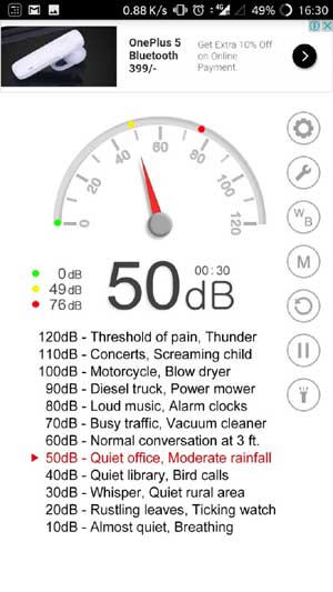
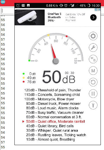
For my application, I did not need much accuracy while measuring the dB values and hence decided to use an easier way of directly calibrating the ADC values with dB values. For this method, we will need an SPL meter (A SPL meter is an instrument which could read dB values and display it), but sadly I didn't have one and sure most of us won't. So we can use the android application called “Sound meter” which could be downloaded from play store for free. There many such types of application and you can download anything of your choice. These applications use the phone’s inbuilt microphone to detect the noise level and display it on our mobile. They are not very accurate, but would surely work for our task. So let’s begin by installing the Android application, mine when opened looked something like this below
As I said earlier the relation between dB and Analog values will not be linear hence we need to compare these two values at different intervals. Just note down the value of ADC being displayed on the screen for different dB displayed on your mobile phone. I took about 10 readings and they looked like this below, you might vary a bit
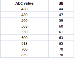
Open an excel page and type in these values, for now on we will be using Excel to find the regression values for the above number. Before that let's plot a graph and check how they both relate to, mine looked like this below.
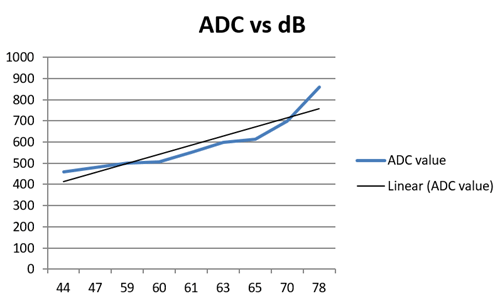
As we can see the value of dB is not related linearly with ADC, meaning you cannot have a common multiplier for all ADC values to obtain its equivalent dB values. In such case we can utilize the “linear regression” method. Basically, it will convert this irregular blue line to the closest possible straight line (black line) and give us the equation of that straight line. This equation can be used to find the equivalent value of dB for every value of ADC that the Arduino measures.
In excel we have a plug-in for data analysis which will automatically calculate the regression for your set of values and publish its data. I am not going to cover how to do it with excel since it outside the scope of this project, also its easy for you to Google and learn it. Once you calculate the regression for the value, excel will give some values like shown below. We are interested only in the numbers that are highlighted below.
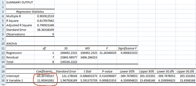
Once you get these numbers you will be able to form the below equation like
ADC = (11.003* dB) – 83.2073
From which you can derive the dB to be
dB = (ADC+83.2073) / 11.003
You might have to drive your own equation since the calibration might differ. However, keep this value safe for we will need it while programming the Arduino.
Arduino Program to measure Sound level in dB:
The complete program to measure dB is given below, few important lines are explained below
In these above two lines, we read the ADC value of pin A0 and convert it to dB using the equation that we just derived. This dB value might not we accurate to the true dB value but, remains pretty much close to the values displayed on the mobile application.
adc= analogRead(MIC); //Read the ADC value from amplifer
dB = (adc+83.2073) / 11.003; //Convert ADC value to dB using Regression values
To check if the program is working properly we have also added an LED to digital pin 3 which is made to go high for 1 sec when the Arduino measures a loud noise of above 60dB.
if (dB>60)
{
  digitalWrite(3, HIGH);   // turn the LED on (HIGH is the voltage level)
  delay(1000);                       // wait for a second
  digitalWrite(3, LOW);
}
Working of Arduino Sound Level Meter:
Once you are ready with the code and hardware, just upload the code and open your serial monitor to look at the dB values measured by your Arduino. I was testing this code in my room where there was not much noise except for the traffic outside and I got the below values on my serial monitor and the android application also displayed something close to this
The complete working of the project can be found at the video given at the end of this page. You can use to project to detect sound in the room and check if there is any activity or how much noise is generated in each classroom or something like that. I have just made an LED to go high for 2 seconds if there is sound recorded above 60dB.
The working is oddly satisfying, but can sure be used for projects and other basic prototypes. With few more digging I found that the problem was actually with the hardware, which was still giving me noise now and then. So I tried out other circuits which is used in the spark fun microphone boards that has a low-pass and high-pass filter. I have explained the circuit below for you to try.
Amplifier with Filters Circuit:
Here we have used Low pass and high pass filters with Amplifier to reduce the noise in this sound level measurement circuit so that accuracy can be increased.

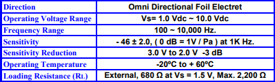
In this above circuit, we have used the popular LM358 amplifier to amplify the signals from microphone. Along with amplifier we have also used two filters, the high-pass filter is formed by R5, C2 and the low-pass filter is used by the C1 and R2. These filters are designed to allow frequency only from 8Hz to 10KHz, since the low pass-filter will filter anything below 8Hz and the High Pass filter will filter anything above 15KHz. This frequency range is select is because my condenser microphone works only from 10Hz to 15KHZ as shown in the datasheet below.
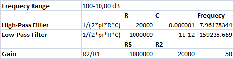
If your frequency demand changes then you can use the below formulae to calculate the value of Resistor and capacitor for your required frequency.
Frequency (F) = 1/(2πRC)
Also, note that the value of resistor used here will also affect the Gain of the amplifier. Calculation for the value of resistor and capacitor used in this circuit is shown below. You can download the excel sheet from here for modifying the values of Frequency and calculating the regression values.
The former circuit worked satisfactory for my expectations, so I never tried this one. If you happen to try this circuit do let me know if it functions better than the previous one through the comments.
Complete Project Code
const int MIC = 0; //the microphone amplifier output is connected to pin A0

int adc;

int dB, PdB; //the variable that will hold the value read from the microphone each time

void setup() {

Serial.begin(9600); //sets the baud rate at 9600 so we can check the values the microphone is obtaining on the Serial Monitor

  pinMode(3, OUTPUT);

}
void loop(){
  PdB = dB; //Store the previous of dB here


adc= analogRead(MIC); //Read the ADC value from amplifer

//Serial.println (adc);//Print ADC for initial calculation

dB = (adc+83.2073) / 11.003; //Convert ADC value to dB using Regression values
if (PdB!=dB)

Serial.println (dB);
if (dB>60)

{

  digitalWrite(3, HIGH);   // turn the LED on (HIGH is the voltage level)

  delay(2000);                       // wait for a second

  digitalWrite(3, LOW);

}

//delay(100);

}
Comments
I'm beginning a project where my aim is use an Arduino system combined with a compatible DB reader to measure noise levels. I want to then record the noise levels and produce some kind of output, like a chart for someone to be able to read and see what noise levels were present. I am a bit intimidated by this project as I have the "grove starter kit" for my Arduino system and don't think their are any compatible DB sensors for the device. Could you recommend any particular parts and some advice to help me get started?
circuit not working
Why? Post the error and i should be able to help you to get it working
i have lm380 and lm741 which 1 is the best to build sound level meter with
What will be the circuit diagram and the program code if I add a LCD?
I had try this project. But, the value in serial monitor just showing one value (77 dB) and the led always turn on. Do you know the causes?
And I confuse, where the R4 (5k ohm) connected to?
The R4 5k ohm is not a resistor it is a Potential divider. The values should change, please check your circuit
I truly, very appreciate this tutorial and the circuit works. But when I talk/increase environment sound why doesnt it affect the dB displayed? After I shout the dB didnt increase...any suggestions?
The values should change even for slight noise changes, please check the circuit and check if the analogRead is reading different values. Adjust the pot to control the sensitivity of the meter
I am just finish this project and the serial monitor showing the data in dB, but when I shout, the dB values doesnt increase. The values increase shen I touching the sensor.
I think the microphone isnt sensitive enough, do you?
In material requirements, there is POT variable 10k, where I should connect the POT variable 10k?
Where should I connect the potentiometer?
Can this project be used to detect sound between 40-120 dB?
Yes, you can detect higher ranges but you will get a lot of noise
A serious SPL has several amplifiers with scaled gains switched in function of the noise level, an dB(A) or dB(C) filter and a logarithming rectifier before the ADC.
Please remember that 10dB is a factor 10, 60dB a factor 1000000 and you will attempt to get that with a linear 10bit ADC?
;-)
What are the values for the resistors and capacitors of the LM386 circuit? They are unclear based on the diagram and your video. Also, will the circuit be able to pick up something like 120dB and do we need the 10K variable POT?
120dB??? I doubt so!!
As the author has explained this is just a crude dB meter do not expect much from it
Hello,
I've followed your instructions but when I connect it to the Arduino it doesn't read it as fast as yours. For example, it stops and then appears 4 continuated values. Also the values doesn't adjust much to the ambiental sound.
Could you help me?
I would suggest you to check you hardware connection, may be the ADC is taking more time in reading values. I cannot offer much help remotely, try using the serial monitor to find where you program actually get slaggy
Why didn't you just use 10*log(rms/cal) to express dB ? That's damn definition of SPL dB :)
You say function dB(Volts) is not linear (which is true) and then you use linear regression ? :D
What are the values for the resistors and capacitors of the LM386 circuit? They are unclear based on the diagram and your video. Also, will the circuit be able to pick up something like 120dB and do we need the 10K variable POT?
where did this value come from?
" dB = (adc+88.2078)/11.008; "
thank you
devreyi oluşturdum ardiuno tamam ama değer okuyamıyorum yardımcı olur musunuz?
Do you have the proteus file to share ?
Marco
what are the values of resistors in LM386 circuit
are they 100 ohm ,400 ohm or 100k,400k???
is it 50k or 5k in potential divider??
Hi Im trying to do this project using ATMEGA 164p is this possible can I use the same circuit for the amplifier and microphone then just change the code.
I am trying to create a sound level meter with an ESP 32. Which sensor would you take and which amplifier is suitable for it, so that I can cover the frequency range from 20Hz to 20kHz?
Can anyone help me here?
HI,
first of all thanks for sharing this project.
I'm trying to follow your instruction but I coping with some issues:
Ones linked to the laptop, the serial monitor printed only10 and 11 values (as the picture below).
Can you tell me the reason?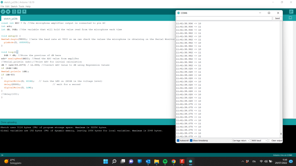
I'm attaching the picture of the circuit made by my self based on your instructions:
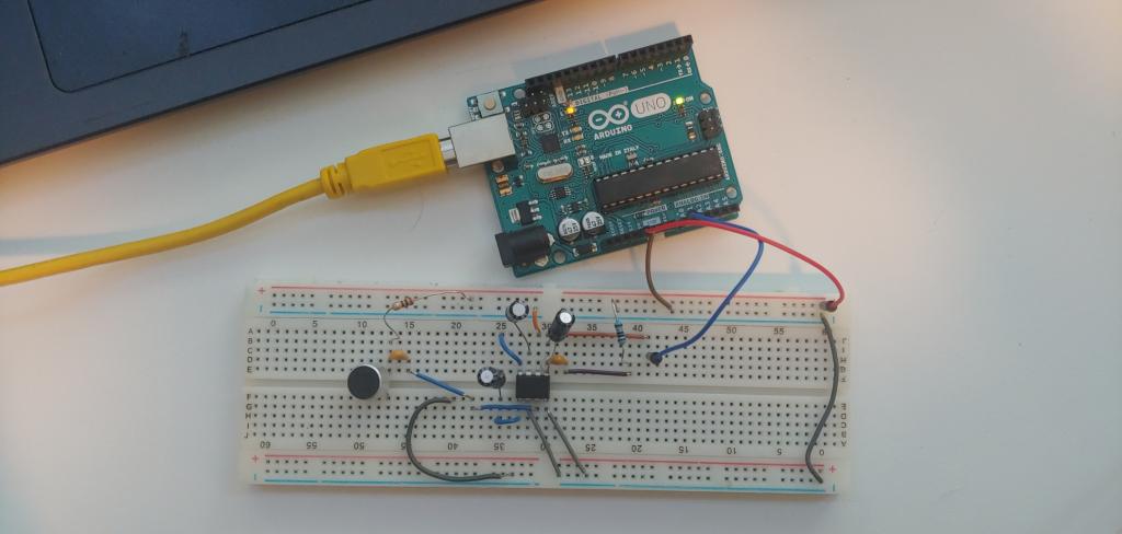
Best,
Andrea

very useful