
 using Arduino IDE")
Arduino would have been the first board for many hobbyists (including me) and engineers out there when they started with electronics. However, as we start building more and dig deep we would soon realise that Arduino is not industry ready and its 8-bit CPU with a ridiculously slow clock, it does not give you enough juice for your projects. Hopefully though, we have the new STM32F103C8T6 STM32 Development Boards (Blue Pill) in the market now which can easily outperform Arduino with its 32-bit CPU and ARM Cortex M3 architecture. Another honey pot here is that we can use the same old Arduino IDE to program our STM32 Boards. So in this tutorial, let us get started with the STM32 to know a bit of basics about this board and blink the on-board LED using the Arduino IDE.
Apart from the STM32 Blue pill board used in this tutorial, there are many other popular STM32 boards like the STM32 Nucleo Development board. If you are interested you can also check out the review on STM32 Nucleo 64 boards and if you want to learn how to use them and program them using the STM32 CubeMX and True studio, you can check out the tutorial on getting started with STM32 Nucelo64.
Materials Required
- STM32 – (BluePill) Development Board (STM32F103C8T6)
- FTDI Programmer
- Breadboard
- Connecting wires
- Laptop with Internet
Introduction to the STM32 (Blue Pill) Boards
The STM32 board a.k.a Blue Pill is a Development board for the ARM Cortex M3 Microcontroller. It looks very much similar to the Arduino Nano but it packs in quite a punch. The Development board is shown below.
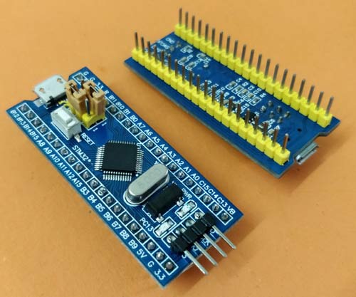
These boards are extremely cheap compared to the official Arduino boards and also the hardware is open source. The microcontroller on top of it is the STM32F103C8T6 from STMicroelectronics. Apart from the Microcontroller, the board also holds two crystal oscillators, one is an 8MHz crystal, and the other is a 32 KHz crystal, which can be used to drive the internal RTC (Real Time Clock). Because of this, the MCU can operate in deep sleep modes making it ideal for battery operated applications.
Since the MCU works with 3.3V, the board also houses a 5V to 3.3V voltage regulator IC to power the MCU. Even though the MCU operates at 3.3V most of its GPIO pins are 5V tolerant. The pin of the MCU are neatly pulled out and labelled as header pins. There are also two on-board LEDs, one (red colour) is used for power indication, and the other (green colour) is connected to the GPIO pin PC13. It also has two header pins which can be used to toggle the MCU boot mode between programming mode and operating mode, we will learn more about these later in this tutorial.
Now few people might be wondering why this board is called as “Blue Pill”, well seriously I do not know. May be since the board is blue in colour and can give a boosted performance to your projects someone came up with this name in it just stayed. This is just an assumption and I have no source to back it up.
STM32F103C8T6 Specifications
The ARM Cortex M3 STM32F103C8 Microcontroller is used in the Blue pill board. Unlike the name, “Blue Pill” the Microcontrollers name STM32F103C8T6 has a meaning behind it.
- STM » stands for the manufacturers name STMicroelectronics
- 32 » stands for 32-bit ARM architecture
- F103 » stands to indicate that the architecture ARM Cortex M3
- C » 48-pin
- 8 » 64KB Flash memory
- T » package type is LQFP
- 6 » operating temperature -40°C to +85°C
Now let us look into the specifications of this Microcontroller.
Architecture: 32-bit ARM Cortex M3
Operating Voltage: 2.7V to 3.6V
CPU Frequency: 72 MHz
Number of GPIO pins: 37
Number of PWM pins: 12
Analog input Pins: 10 (12-bit)
USART Peripherals: 3
I2C Peripherals: 2
SPI Peripherals: 2
Can 2.0 Peripheral: 1
Timers: 3(16-bit), 1 (PWM)
Flash Memory: 64KB
RAM: 20kB
If you want to know more on technical features of the Microcontroller then you can refer to its Datasheet. You might also be interested in the Reference manual and the Errata sheet of the Microcontroller as well which is also linked.
STM32 Pin Details
The complete pin-outs of the STM32 Blue pill board is shown below. As you can see each pin is neatly labeled against it. The labling is also similar to the Arduino boards. That is the G is used to denote the ground pin, 3.3V outpus a regulated 3.3V and the 5V pin can either be used to power the board or obtain the +5V if powered via micro USB. The on-board LED is connected to the PC13 pin of the Microcontrller.

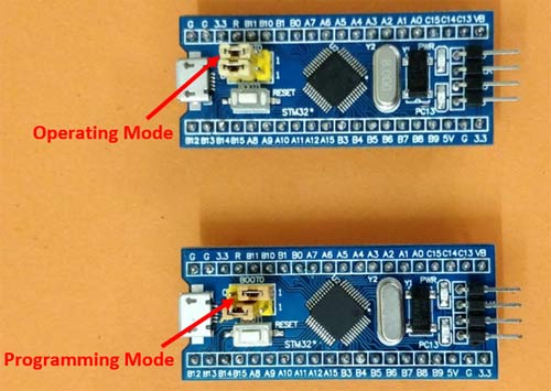
Unlike Arduino boards, the STM32 development board has to be manually set to programming mode using the boot 1 and boot 0 jumper wires. The position of Boot 1 is normally not disturned. But the boot 0 jumper has to be set as 3.3V for programming mode and set to ground for operating mode. We will learn more about it when we upload the program on our board.
STM32 Blue Pill Programming - How to Program STM32F103C8T6
The STM32 is just another microcontroller form the STMicroelectronics family. So all the existing methods to program an ARM chip can be used for the STM32 board as well. One famous and commonly used IDE is the Keil ARM MDK and apart from that we can also use IAR workbench, Atollic TrueStudio, MicroC Pro ARM, Crossworks ARM, Ride 7, PlatformIO+STM32 etc.
But what made this board a lot popular is its ability to be programmed with the Arduino IDE. This way people can get started and build projects with STM32 in no-time since many will be familiar with Arduino IDE and its easy to use programming language and readily available libraries. So in this STM32F103C8T6 Arduino IDE tutorial we will using the Arduino IDE to get started with STM32.
Circuit Diagram
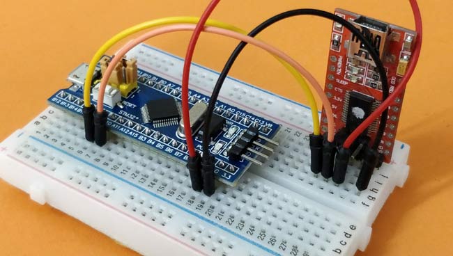
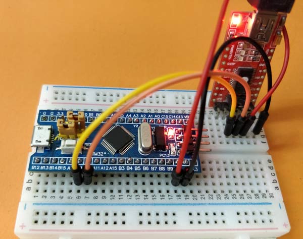
To program the STM32 Blue Pill board directly from Arduino IDE we need to use a Serial FTDI board. This board is connected to the Rx and Tx pin of the STM32 as shown below.

The Vcc pin of the FTDI board is connected to the STM32 5V pin of power the board. The ground is connected to the Ground of STM32. The Rx and Tx pin of the FTDI board is connected to the A9 and A10 pin of the STM32 respectively. Where the A9 is the Tx pin of STM32 MCU and the A10 is Rx pin.
Programming SMT32 through Micro USB Board without Serial
Now you might be wondering why we are not using the micro-USB port to program the board just like any other Arduino boards. Well!! actually, we can but for this tutorial we chose not to. The STM32 Blue Pill development board when purchased does not come with a bootloader to make it Arduino IDE compatible. However, this bootloader can be flashed into the STM32 board and then the micro-USB port can be directly used to upload the programs. But at the time of documenting this article the bootloader has some bugs and is currently still under development. If you want more updates you can check out the article on Programming STM32 Blue pill using usb port.
Preparing the Arduino IDE for STM32 (Blue Pill)
Follow the below steps to download and prepare the Arduino IDE to be used with the STM 32 Development board.
Step 1:- If you have not yet installed the Arduino IDE, download and install it from this link. Make sure you select your correct operating system.
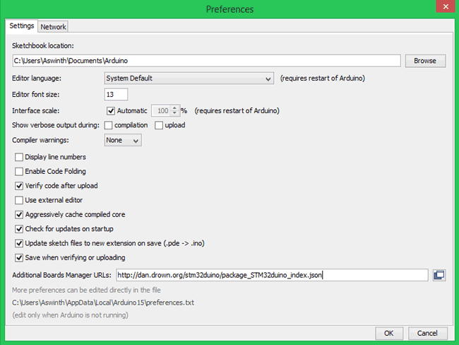
Step 2:- After Installing the Arduino IDE open and download the required packages for the STM32 board. Thi can be done by selecting File -> Preferences.
Step 3:- Clicking on Preferences will open the below shown dialog box. In the additional Boards Manager URL text box paste the below link
http://dan.drown.org/stm32duino/package_STM32duino_index.json
and press OK.
Step 4:- Now go to Tool -> Boards -> Board Manager. This will open the Boards manager dialog box, search for “STM32F1” and install the package that appears.
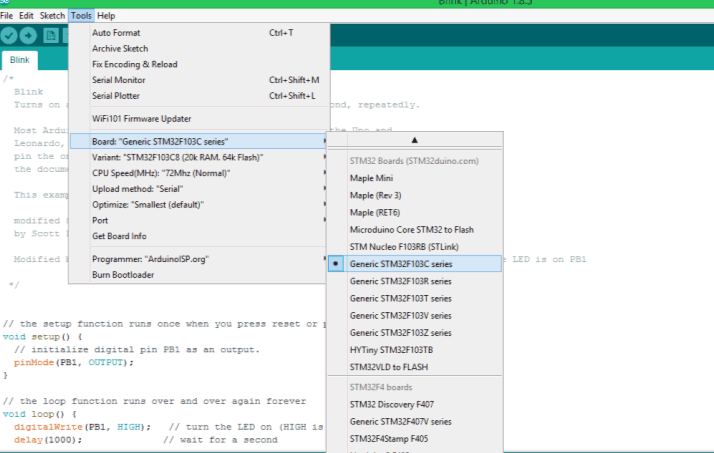
Step 5:- After the package, installation is completed. Go to Tools and scroll down to find the Generic STM32F103C series as shown below. Then make sure the variant is 64kFlah type, CPU speed is 72MHz and change the upload method to Serial.
Step 6:- Now, connect your FTDI board to the computer and check to which COM port the FTDI board is connected to using device manager. Then, select the same port number in Tools->Port
Step 7:- After all the changes are made, check the bottom right corner of the Arduino IDE and you should notice the following setting being set. My FTDI board is connected to COM7 but yours might differ

Now the Arduino IDE is ready to program the STM 32 Blue Pill Development Boards.
Uploading an stm32f103c8t6 Example Code
Let us upload the Sample Blink Program from the Arduino IDE to the STM32 Blue Pill board to make sure everything is working properly. The example program can be found at
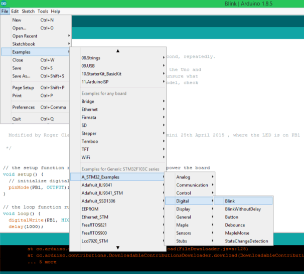
In the example program that opens, we have to make a small change. By default the program will be written for PB1 but on our board the on-board LED is connected to PC13 so replace all PB1 with PC13 and we are good to proceed. The complete example program which is modified can also be found at the bottom of this page.
The code inside the loop function alone is shown below, where we can notice that the PC13 pin is kept HIGH (on) for 1000 millisecond and then turned LOW (off) for another 1000 millisecond and this is done for infinite times since it is in loop function. Thus the LED appears to be blinking with an interval of 1000 millisecond.
  digitalWrite(PC13, HIGH);   // turn the LED on (HIGH is the voltage level)
  delay(1000);              // wait for a second
  digitalWrite(PC13, LOW);    // turn the LED off by making the voltage LOW
  delay(1000);              // wait for a second
As told earlier the STM32 Board has to be put into programming mode before uploading any program, to do this put the boot 0 jumper in the lower position. The Jumper position for Programming mode and Operating mode are shown below.
Now, to upload the program make sure the boot 0 jumper is in programming mode as shown above and then press the Reset button. As soon as you press the reset button the board will enter into programming mode and the green LED will be turned off, this indicates that the board is ready for upload. Press the upload button on the Arduino IDE and your program should get compiled and uploaded. If everything has worked as expected then you should see the following on yor Arduino IDE console.
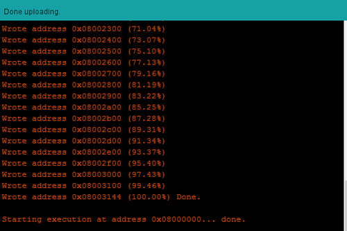
Note: Sometimes the Arduino IDE will show done Uploading even if the program was not uploaded successfully. So drag open your console to check the write address percentage (orange colour text) to make sure the Upload has been done successfully.
Working of STM32 Blink Program
If the Program has been uploaded successfully then you should see the Green LED blinking at a 1 second interval as shown in the video below. You can also fiddle around with the program to increase or decrease the delay.
After uploading the program the boot 0 should be changed back to operating mode so that next time when the Board is powered the uploaded program starts to get executed automatically. The programming mode and operating mode positions are shown in the above image.
Hope you understood the tutorial and found it useful to get started with STM32 Board. You can also check out the other stm32f103 programming tutorials to learn more about the board. If you have any problem leave them in the comment section, also tell me what projects we should try with this STM32 board.
Complete Project Code
/*

 circuitdigest.com

 Sample STM32 Blink Program for Blue Pill board

 */

// the setup function runs once when you press reset or power the board

void setup() {

  // initialize digital pin PC13 as an output.

  pinMode(PC13, OUTPUT);

}
// the loop function runs over and over again forever

void loop() {

  digitalWrite(PC13, HIGH);   // turn the LED on (HIGH is the voltage level)

  delay(1000);              // wait for a second

  digitalWrite(PC13, LOW);    // turn the LED off by making the voltage LOW

  delay(1000);              // wait for a second

}
Comments
"Now few people might be wondering why this board is called as “Blue Pill”, well seriously I do not know. May be since the board is blue in colour and can give a boosted performance to your projects someone came up with this name in it just stayed. This is just an assumption and I have no source to back it up."
Because there was also one in red color PCB.
So someone name them with name of the pills from The Matrix (movie): Red Pill and Blue Pill.
http://dan.drown.org/stm32duino/package_STM32duino_index.json
I no longer get that error but I also see no files to install in the Boards and Board Managers for the STM32F1.
What am I missing?
Thank you.
Hello,
I have been trying to program STM32 Bluepill,following this tutorial,but i every time i try to upload code i get the following error,
Failed to init device.
stm32flash 0.4
Using Parser : Raw BINARY
Interface serial_w32: 115200 8E1
Please guide me if someone has solution?
i have tried every solution given on internet.
First time trying the STM32F103C8T6
It says 'done uploading'
I get the following error message...
Please help!!!
............................................
maple_loader v0.1
Resetting to bootloader via DTR pulse
Searching for DFU device [1EAF:0003]...
dfu-util - (C) 2007-2008 by OpenMoko Inc.
This program is Free Software and has ABSOLUTELY NO WARRANTY
Couldn't find the DFU device: [1EAF:0003]
I'm getting the same error as well. Which USB to serial module are you using? Do let me know if you found a solution. I'll reply likewise.
@Ashwinth, how about helping?
Same error happened to me, when I first tried it
Save the program to file, shut down the Arduino IDE, remove power from the board,
then restart, re-power. Now I can upload.
For an upload to work, the BOOT0 jumper must be set to 1 (near the CPU), and if you already uploaded a program before, press RESET, or power-cycle.
The program should start immediately, even if the jumper is left in the 1 position.

Hello!
You guys should try to use inertial sensors with this stm32 and arduino. I think its a very good project to develop.