
Many of us should be familiar with the popular microcontrollers and development boards like Arduino, Raspberry Pi, ESP8266, NoduMCU, 8051, etc. In fact, for most people, Arduino would have been their first development board, but as we dig deep and begin professional designs, we will soon realize the limitations of Arduino (like cost, versatility, stability, speed, etc.) and understand the need to shift into a more native Microcontroller platform like PIC, STM, Renesas, etc.
We have already covered a sequence of PIC Microcontroller tutorials, which guides beginners for learning PIC microcontrollers. Similarly, starting with this article, we will also plan a sequence of STM32 Nucleo64 Development Board Tutorials which can help absolute beginners to learn and develop using the STM32 Platform. Nucleo64 Development Boards are low cost and easy to use platform for professional developers as well as for hobbyist. If you are completely new to the STM32 Nucleo64 Development Boards, do check out this Nucleo64 Review video to understand the basics of this board before you proceed further. The video also demonstrates how to program STM32 using ARM Mbed Platform but for this tutorial, we will use another free to use platform from ST Microelectronics called TrueSTUDIO.
Note: There are many versions of STM32 Nucleo64 Development Boards, the particular board used in this tutorial is NUCLEO-F030R8. We have selected this board mainly because of its low cost. Even, if you have a different version, most things discussed in the tutorial will suffice for you to get started.
Selecting and Downloading the Required Development Platforms for Nucleo64 Boards
Getting started with any microcontroller will need a programming IDE like we have Arduino IDE for Arduino boards, Atmel Studio for AVR microcontroller, MP Lab for PIC, etc. So here we also need an IDE for our STM32 Nucleo64 Boards to perform programming and debugging. The STM32 family consists of 32-bit Microcontrollers that support the following IDEs and toolchains:
- IAR Embedded Workbench® for ARM® (EWARM).
- MDK-ARM Keil
- TrueSTUDIO
- System Workbench for STM32
Here for our tutorials, TrueSTUDIO will be used for writing, compiling, and debugging code because it is free to download and use even for commercial projects without any license requirement. Then STM32CubeMX will be used to generate peripheral drivers for STM32 boards to make programming easy. To upload our program (hex file) into our development board, people normally use the STM32 ST-LINK Utility tool, but instead, we will be using TrueSTUDIO itself to do this. TrueSTUDIO has a debug mode that allows programmers to upload the hex file directly to the STM32 board. Both TrueSTUIO and STM32CubeMX is easy to download, just follow the link below, signup and download the setup. Then install them on your Laptop.
Circuit Diagram and Hardware setup
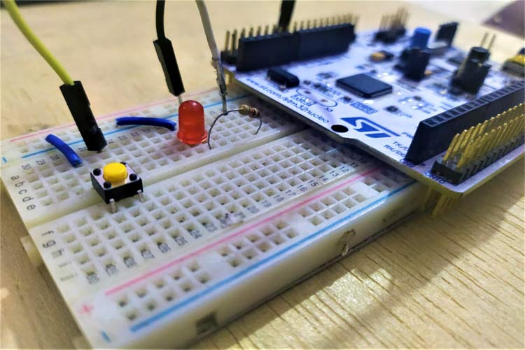
Before we proceed with the software section and coding, let's prepare our board for this project. As mentioned earlier in this article, we are going to control an LED using a push button. Now, if you have seen the video linked above, you should already know that your STM32 Development Board has two sets of connector pins on either side called ST Morpho pins. We have connected a push-button and an LED to these pins as shown in the circuit diagram below.

Circuit connections are easy for this project, we need to connect an LED at PA5 of PORTA and a switch at PC13 of PORTC with respect to GND. Once the connections were made, my test set-up looked like this.
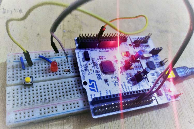
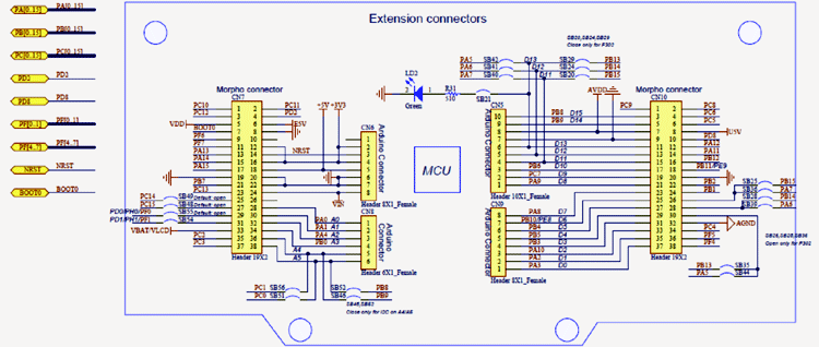
Alternatively, we can also use the inbuilt LED and push button on the board. These inbuilt LEDs and push-button also connected at the same pin as shown in the circuit diagram. We have added external components only for practice. The below pin diagram of the STM32 Development Board will come in handy to know where each morpho pins are connected to onboard.
Getting started with STM32CubeMX for STM32 Nucleo64 Development Boards
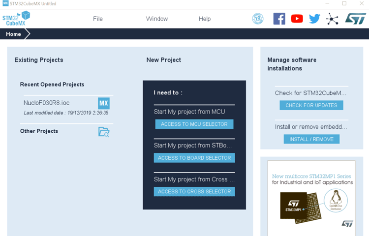
Step 1: After installation, launch STM32CubeMX, then select the access board selector to select the STM32 board.
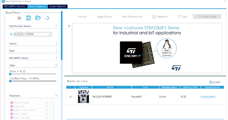
Step 2: Now search board by your STM32 board name like NUCLEO-F030R8 and click on the board showing in the picture. If you have a different board search for its respective name. The software will support all STM32 development boards from ST Microelectronics.
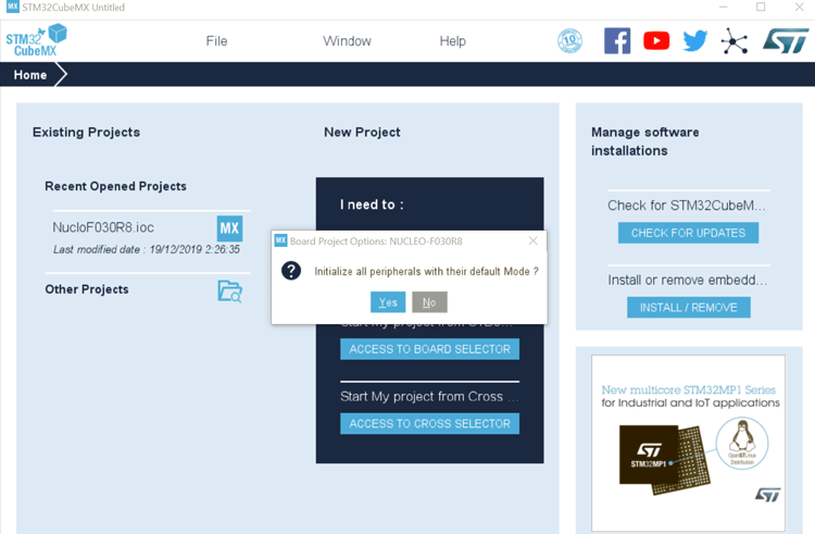
Step 3: Now click on yes as shown in the picture below, to initialize all the peripherals in their default mode. We can later change the required ones as needed by our project.
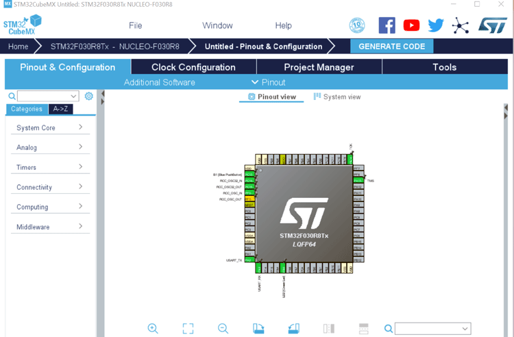
After clicking on ‘Yes’, the screen will similar to the below picture and green color pin indicating that they are initiated by default.
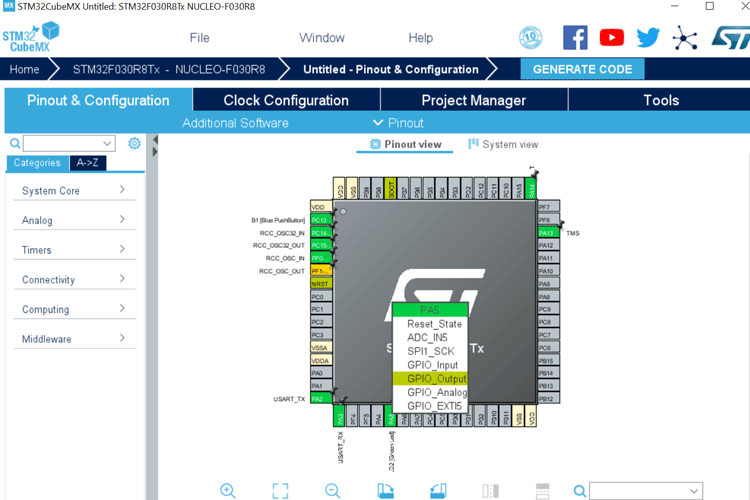
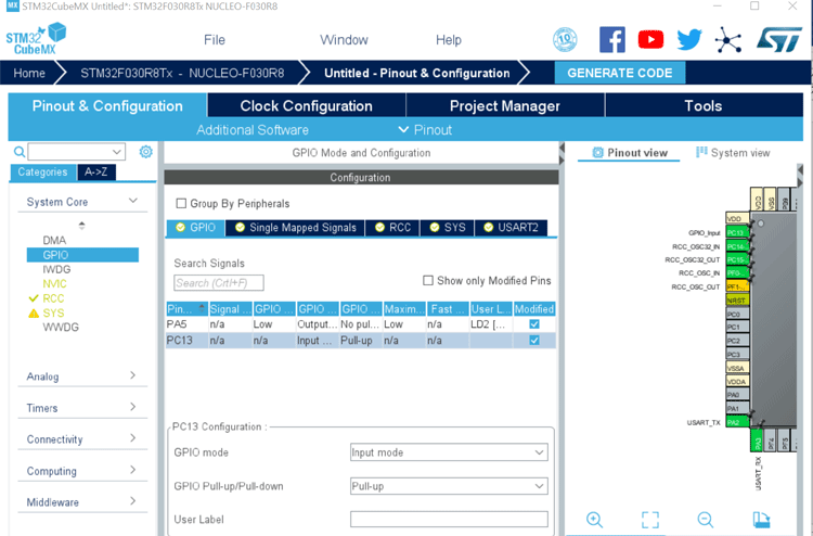
Step 4: Now users can select the desired setting from the categories. Here in this tutorial, we are going to toggle an LED using a push button. So, we need to make the LED pin as output and switch pin as INPUT.
You can select any pin, but I am selecting PA5 and changing its state to GPIO_Output to make it work as an output pin as shown in the below picture.
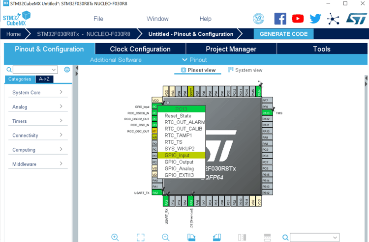
Similarly, I am selecting PC13 as GPIO_Input so that I can read the status of my push-button.
Alternatively, we can make also configure pins from the pinout and configuration tab as well as shown below.
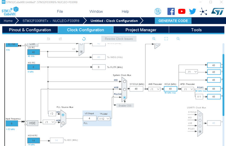
Step 5: In the next step, the user can set the desired frequency for the microcontroller and pins according to external and internal oscillator. By default, an internal 8 MHz crystal oscillator is selected and by using PLL, this 8 gets converted to 48MHz. Meaning by default STM32 board or microcontroller and Pins will work on 48MHz.
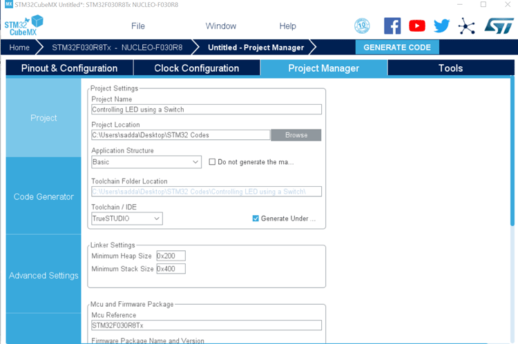
Step 6: Now move in the project manager and give a name to your project, project location, and select toolchain or IDE. Here we are using TrueSTUDIO, so I have selected the same as shown below.
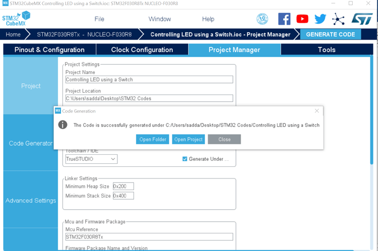
Step 7: Now click on Generate Code mark by the red circle in the below picture.
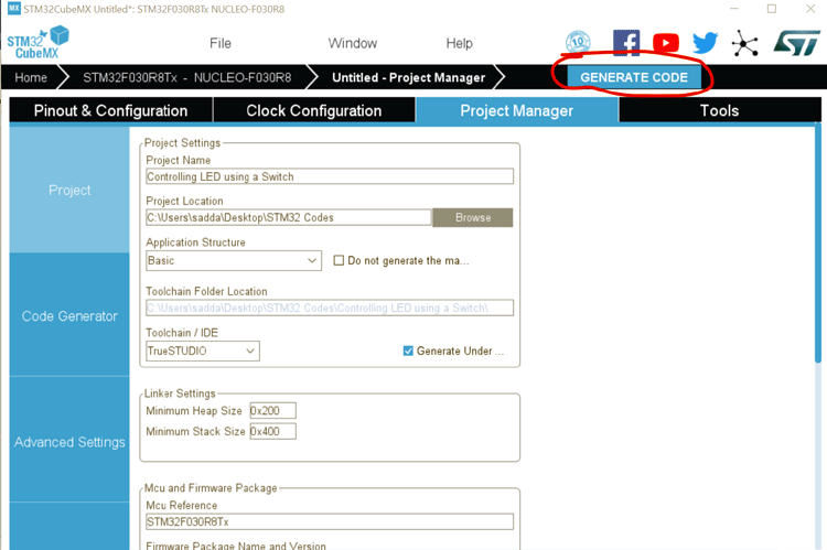
Step 8: Now you will see a popup as given then click on open project. But, make sure you have installed TrueSTUDIO before this step.
Programming STM32 Nucleo64 Development Board using TrueSTUDIO
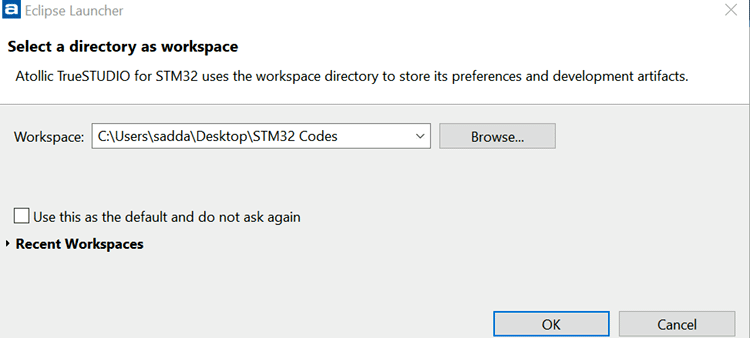
Now your code or project will open in TrueSTUDIO automatically if TrueSTUDIO asks for workspace location then provide a workspace location or go with the default location.
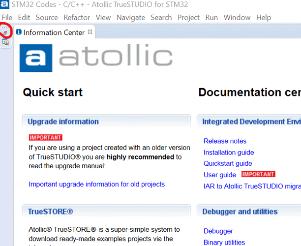
The user will see the below-given screen and then need to click at the corner mark in red color.
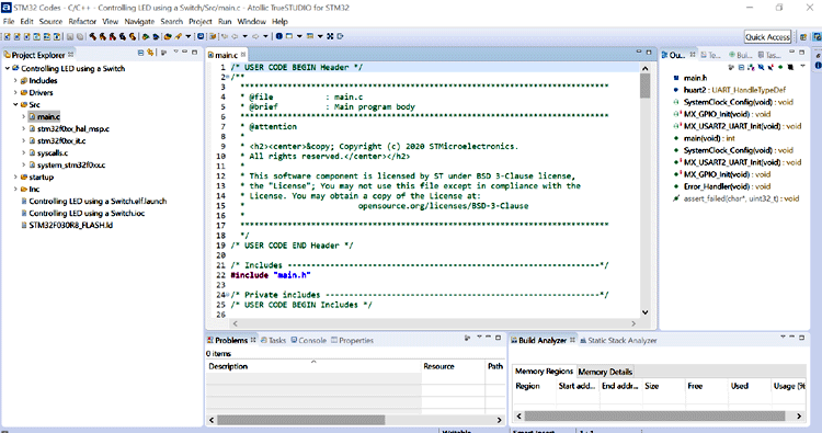
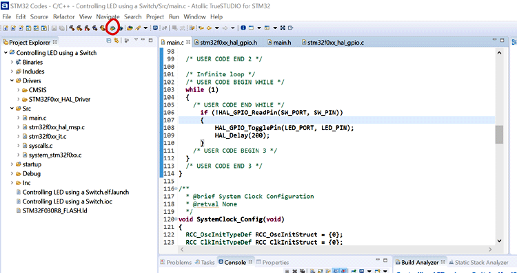
And now we can see code in our TreuSTUDIO IDE. On the left side under the ‘src’ folder we can see other program files (with .c extension) that have already been generated for us from STM32Cube. We just have to program the main.c file. Even in main.c file we will already have few things set-up for us by the CubeMX we only have to edit it to suit our program. The complete code inside the main.c file is given at the bottom of this page.
STM32 Nucleo64 Program to Control LED using Push Button
Since all the required driver and code is generated by STM32CubeMX, we only have to configure an LED pin as output and a push-button as Input. The program for controlling led using the push button should be written in the main.c file. The complete program can be found at the bottom of this page. The explanation of it is as follows
We only have written code for toggling the LED using the push button. To achieve this, we first define pins for LED and push-buttons. Here we have defined a LED at Pin 5 number of PORTA
#define LED_PORT GPIOA
#define LED_PIN GPIO_PIN_5
And define switch at Pin Number 13 of PORTC.
#define SW_PORT GPIOC
#define SW_PIN GPIO_PIN_13
Then in the main function, we have initialized the all used peripherals.
/* Initialize all configured peripherals */
MX_GPIO_Init();
MX_USART2_Init();
And then read the push button using the if statement and if found button press (LOW) then LED will toggle its state.
While (1)
{
/* USER CODE END WHILE */
If (!HAL_GPIO_ReadPin(SW_PORT, SW_PIN))
{
HAL_GPIO_TogglePin(SW_PORT, LED_PIN);
HAL_Delay(200);
}
/* USER CODE BEGIN 3 */
}
Here HAL_GPIO_ReadPin(SW_PORT, SW_PIN) function has two arguments, one is PORT and the other is a pin at which switch is connected and this pin is configured as INPUT while configuring peripheral in STM32CubeMX.
Debugging and Uploading Code to STM32 Necleo64 Development Board using TrueSTUDIO
Now connect your board to the computer using the programmer cable. Once you connect it, the driver required for the board should be automatically downloaded, you can check this using the device manager.
Then, Press the debug icon marked by the red circle in the below-given picture to compile the program and enter into debug mode.
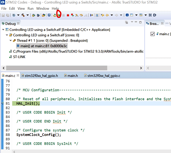
In debug mode, the code will automatically be uploaded. Now we need to run the code by pressing ‘Resume’ or F8 (marked in the red circuit in the below picture).
Now we can test the control of LED by pressing the push button. According to the code, the LED should change its state every time you press the push button. The complete working can also be found in the video linked at the bottom of this page.
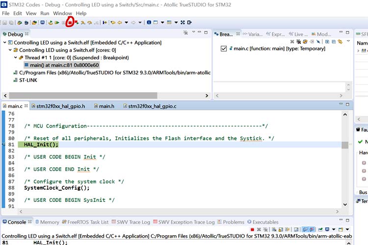
After testing, we can also terminate the program by pressing the terminate icon, marked by the red circle in the below picture.
Complete Project Code
/* USER CODE BEGIN Header */
/**
******************************************************************************
* @file : main.c
* @brief : Main program body
******************************************************************************
* @attention
*
* <h2><center>© Copyright (c) 2020 STMicroelectronics.
* All rights reserved.</center></h2>
*
* This software component is licensed by ST under BSD 3-Clause license,
* the "License"; You may not use this file except in compliance with the
* License. You may obtain a copy of the License at:
* opensource.org/licenses/BSD-3-Clause
*
******************************************************************************
*/
/* USER CODE END Header */
/* Includes ------------------------------------------------------------------*/
#include "main.h"
/* Private includes ----------------------------------------------------------*/
/* USER CODE BEGIN Includes */
/* USER CODE END Includes */
/* Private typedef -----------------------------------------------------------*/
/* USER CODE BEGIN PTD */
/* USER CODE END PTD */
/* Private define ------------------------------------------------------------*/
/* USER CODE BEGIN PD */
#define LED_PORT GPIOA
#define LED_PIN GPIO_PIN_5
#define SW_PORT GPIOC
#define SW_PIN GPIO_PIN_13
/* USER CODE END PD */
/* Private macro -------------------------------------------------------------*/
/* USER CODE BEGIN PM */
/* USER CODE END PM */
/* Private variables ---------------------------------------------------------*/
UART_HandleTypeDef huart2;
/* USER CODE BEGIN PV */
/* USER CODE END PV */
/* Private function prototypes -----------------------------------------------*/
void SystemClock_Config(void);
static void MX_GPIO_Init(void);
static void MX_USART2_UART_Init(void);
/* USER CODE BEGIN PFP */
/* USER CODE END PFP */
/* Private user code ---------------------------------------------------------*/
/* USER CODE BEGIN 0 */
/* USER CODE END 0 */
/**
* @brief The application entry point.
* @retval int
*/
int main(void)
{
/* USER CODE BEGIN 1 */
/* USER CODE END 1 */
/* MCU Configuration--------------------------------------------------------*/
/* Reset of all peripherals, Initializes the Flash interface and the Systick. */
HAL_Init();
/* USER CODE BEGIN Init */
/* USER CODE END Init */
/* Configure the system clock */
SystemClock_Config();
/* USER CODE BEGIN SysInit */
/* USER CODE END SysInit */
/* Initialize all configured peripherals */
MX_GPIO_Init();
MX_USART2_UART_Init();
/* USER CODE BEGIN 2 */
/* USER CODE END 2 */
/* Infinite loop */
/* USER CODE BEGIN WHILE */
while (1)
{
/* USER CODE END WHILE */
if (!HAL_GPIO_ReadPin(SW_PORT, SW_PIN))
{
HAL_GPIO_TogglePin(LED_PORT, LED_PIN);
HAL_Delay(200);
}
/* USER CODE BEGIN 3 */
}
/* USER CODE END 3 */
}
/**
* @brief System Clock Configuration
* @retval None
*/
void SystemClock_Config(void)
{
RCC_OscInitTypeDef RCC_OscInitStruct = {0};
RCC_ClkInitTypeDef RCC_ClkInitStruct = {0};
/** Initializes the CPU, AHB and APB busses clocks
*/
RCC_OscInitStruct.OscillatorType = RCC_OSCILLATORTYPE_HSI;
RCC_OscInitStruct.HSIState = RCC_HSI_ON;
RCC_OscInitStruct.HSICalibrationValue = RCC_HSICALIBRATION_DEFAULT;
RCC_OscInitStruct.PLL.PLLState = RCC_PLL_ON;
RCC_OscInitStruct.PLL.PLLSource = RCC_PLLSOURCE_HSI;
RCC_OscInitStruct.PLL.PLLMUL = RCC_PLL_MUL12;
RCC_OscInitStruct.PLL.PREDIV = RCC_PREDIV_DIV1;
if (HAL_RCC_OscConfig(&RCC_OscInitStruct) != HAL_OK)
{
Error_Handler();
}
/** Initializes the CPU, AHB and APB busses clocks
*/
RCC_ClkInitStruct.ClockType = RCC_CLOCKTYPE_HCLK|RCC_CLOCKTYPE_SYSCLK
|RCC_CLOCKTYPE_PCLK1;
RCC_ClkInitStruct.SYSCLKSource = RCC_SYSCLKSOURCE_PLLCLK;
RCC_ClkInitStruct.AHBCLKDivider = RCC_SYSCLK_DIV1;
RCC_ClkInitStruct.APB1CLKDivider = RCC_HCLK_DIV1;
if (HAL_RCC_ClockConfig(&RCC_ClkInitStruct, FLASH_LATENCY_1) != HAL_OK)
{
Error_Handler();
}
}
/**
* @brief USART2 Initialization Function
* @param None
* @retval None
*/
static void MX_USART2_UART_Init(void)
{
/* USER CODE BEGIN USART2_Init 0 */
/* USER CODE END USART2_Init 0 */
/* USER CODE BEGIN USART2_Init 1 */
/* USER CODE END USART2_Init 1 */
huart2.Instance = USART2;
huart2.Init.BaudRate = 38400;
huart2.Init.WordLength = UART_WORDLENGTH_8B;
huart2.Init.StopBits = UART_STOPBITS_1;
huart2.Init.Parity = UART_PARITY_NONE;
huart2.Init.Mode = UART_MODE_TX_RX;
huart2.Init.HwFlowCtl = UART_HWCONTROL_NONE;
huart2.Init.OverSampling = UART_OVERSAMPLING_16;
huart2.Init.OneBitSampling = UART_ONE_BIT_SAMPLE_DISABLE;
huart2.AdvancedInit.AdvFeatureInit = UART_ADVFEATURE_NO_INIT;
if (HAL_UART_Init(&huart2) != HAL_OK)
{
Error_Handler();
}
/* USER CODE BEGIN USART2_Init 2 */
/* USER CODE END USART2_Init 2 */
}
/**
* @brief GPIO Initialization Function
* @param None
* @retval None
*/
static void MX_GPIO_Init(void)
{
GPIO_InitTypeDef GPIO_InitStruct = {0};
/* GPIO Ports Clock Enable */
__HAL_RCC_GPIOC_CLK_ENABLE();
__HAL_RCC_GPIOF_CLK_ENABLE();
__HAL_RCC_GPIOA_CLK_ENABLE();
/*Configure GPIO pin Output Level */
HAL_GPIO_WritePin(LD2_GPIO_Port, LD2_Pin, GPIO_PIN_RESET);
/*Configure GPIO pin : PC13 */
GPIO_InitStruct.Pin = GPIO_PIN_13;
GPIO_InitStruct.Mode = GPIO_MODE_INPUT;
GPIO_InitStruct.Pull = GPIO_PULLUP;
HAL_GPIO_Init(GPIOC, &GPIO_InitStruct);
/*Configure GPIO pin : LD2_Pin */
GPIO_InitStruct.Pin = LD2_Pin;
GPIO_InitStruct.Mode = GPIO_MODE_OUTPUT_PP;
GPIO_InitStruct.Pull = GPIO_NOPULL;
GPIO_InitStruct.Speed = GPIO_SPEED_FREQ_LOW;
HAL_GPIO_Init(LD2_GPIO_Port, &GPIO_InitStruct);
}
/* USER CODE BEGIN 4 */
/* USER CODE END 4 */
/**
* @brief This function is executed in case of error occurrence.
* @retval None
*/
void Error_Handler(void)
{
/* USER CODE BEGIN Error_Handler_Debug */
/* User can add his own implementation to report the HAL error return state */
/* USER CODE END Error_Handler_Debug */
}
#ifdef USE_FULL_ASSERT
/**
* @brief Reports the name of the source file and the source line number
* where the assert_param error has occurred.
* @param file: pointer to the source file name
* @param line: assert_param error line source number
* @retval None
*/
void assert_failed(char *file, uint32_t line)
{
/* USER CODE BEGIN 6 */
/* User can add his own implementation to report the file name and line number,
tex: printf("Wrong parameters value: file %s on line %d\r\n", file, line) */
/* USER CODE END 6 */
}
#endif /* USE_FULL_ASSERT */
/************************ (C) COPYRIGHT STMicroelectronics *****END OF FILE****/

Great content,easy to comprehend