

For most people out there, the first embedded development board that they would have worked on would most probably be an Arduino Board. But, like as well all can agree, your Arduino could take you only so far and someday you have to move to a native microcontroller platform. This process can be made a lot easier with this STM32 development board as it can support all Arduino shields to help you on the hardware side and also has many built-in libraries and functions to help you on the software side. Also getting familiar with an STM32 Microcontrollers will help you to easily explore other development modules from ST like the SensorTile.Box which we reviewed earlier. So in this article, let’s take a complete look at this STM32 Nucleo-64 Development boards and learn how to use them.
Now there are many versions of STM32 boards available and this particular one in my hand is called the STM32F401 Nucleo-64. The name STM32 represents that we have a 32-bit Microcontroller on our development board, and the name Nucleo-64 represents that the microcontroller has 64 pins. Similarly, there are many other versions of Nucleo 64 boards like the STM32F103, STM32F303, etc, but once you learn about one board all the others are quite similar.
STM32 Nucleo 64 Development Board Hardware Explanation
Let's begin by unboxing our Development Board. As you can see the complete package only consists of our development board and an instruction card. The instruction card mentions the specifications of the controller, its pinouts, and on the backside, we have some information on how to get started and available toolchain options.
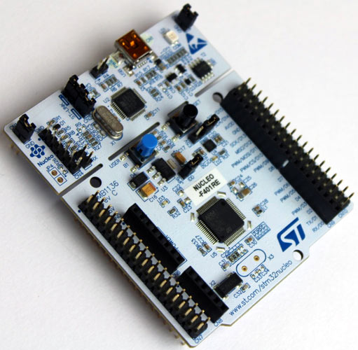
Taking a closer look at the board we can find that the board is divided into two regions. The top section is ST-Link/V2 debugger and programmer while the bottom section is your actual development board. This way you can easily program and debug your board out of the box just with an additional USB cable that can be connected to the USB mini port on the board.
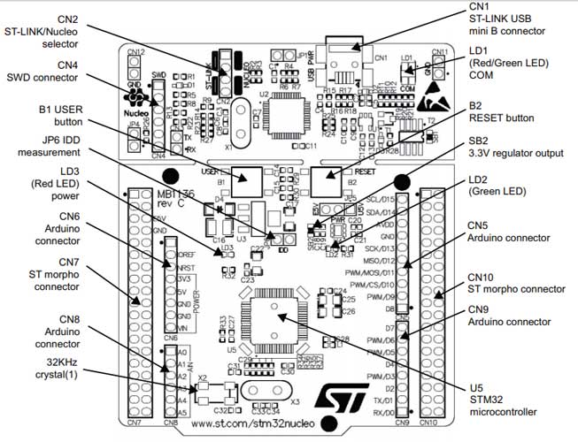
On the first look, the board might seem to have a lot of jumpers and components, but they all are there to make things easy for us. The Two jumpers that you find either side of the board CN11 and CN12 are actually dummy jumper, these jumpers can be used for other purposes if needed in the future. The two jumpers on CN2 are used to connect the programmer and debugger section with our development board. In the future, you can remove these jumpers to use the programmer for other ST microcontrollers through these pins. And this connector pin JP1 can be closed to limit the USB current to 100mA, if left open the maximum current will be 300mA. Over here we have a Tricolor LED (LD1) which turns on as Red when the board is powered and turns to green when the board is successfully programmed and turns orange when there is a communication failure.
Moving down to the development section we have our most important component here, the STM32F401RET6 Microcontroller. This is a 64-Pin 32-bit Microcontroller with an ARM Cortex M4 processor operating at 84MHz. It also has 512 Kb Flash and 96KB SRAM. The Microcontroller has 10 timers of 16-bit and 32-bit and a single 12-bit ADC. It also has three USART, three I2C, four SPI and one USB 2.0 for external communications. You can check the STM32F401 Datasheet to get more technical information.
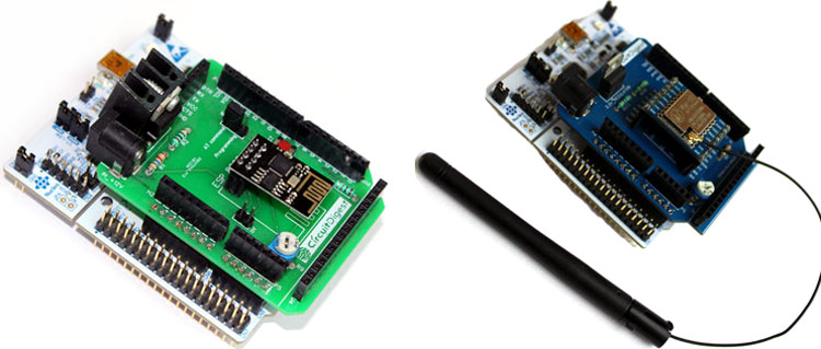
Now here comes the interesting part, as I told you earlier the board supports all Arduino shields. The board has two sets of connectors, the female pins are for Arduino shields which perfectly fit our ESP8266 Wi-Fi Shield and our Semtech Arduino LoRa Shield as you can see in the image below.
The other males are called ST morpho pins which can be used to utilize the reaming pins on our 64-pin microcontroller. Then we have a reset button here and a user-configurable button that is connected to pin PC13 and also an LED here which is connected to pin D13 just like Arduino. To power the board we can either use the USB port or directly provide regulated 5V to the E5V or to the 5V pin here. Remember to change this jumper to indicate how you are powering the board; U5V indicates the board is powered by USB. We also have another interesting jumper pin here called IDD which can be used to measure how much current your microcontroller is consuming by connecting an ammeter to these pins.
Programing the STM32 Nucleo 64 Development Boards
Coming to the software section, the board has a huge library and programming support and can be programmed using Keil, IAR workbench and many other IDEs. But the interesting thing is that it supports ARM Mbed and STM32Cube development environment. For the sake of this article, I decided to use the ARM Mbed platform because it is an online tool and I found it very interesting because you can not only your ST boards with it but many other development boards that use the ARM microcontroller.
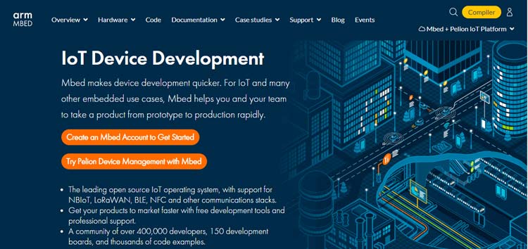
For those who are new, ARM MBED is an online development platform provide by ARM itself and it gives you an embedded operating system, cloud services, and security features to easily create IoT based embedded solutions. It is a huge open source community and getting in detail about it will require a separate article.
Getting Started with STM32F401
But, to get started, use a USB mini cable to connect your STM32 development board with your computer. Once powered, you should notice the LD1 and LD3 LED’s light up in red, and the programmable LED LD2 will be blinking in green color like this.
You will also notice a new flash drive on your computer called “NODE_F401RE”. Open it and you will find two files namely details.txt and mbed.htm as shown below.
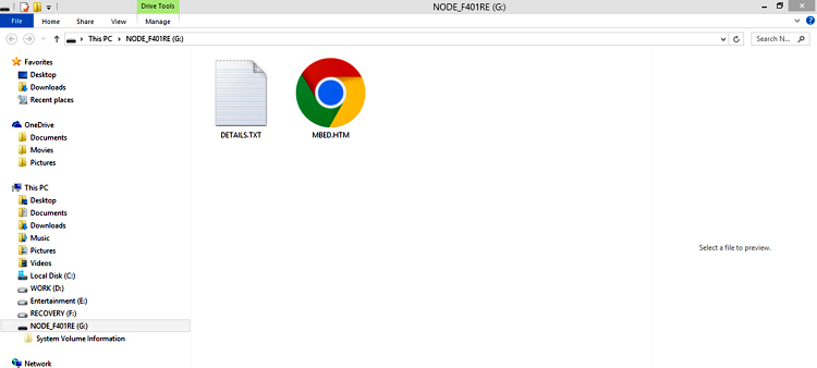
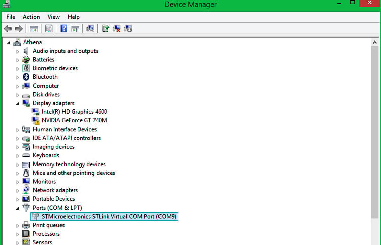
You can launch the Mbed.htm file to directly start programming your board online using arm Mbed. But, before we get there we have installed the required drivers and signup for Mbed. Search for STSW-link009 driver software and download it directly from the ST website, install the driver and make sure the device is discovered correctly in your device manager as shown here.
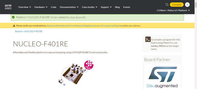
Get back to your mbed platform to sign up on MBED.com with your credentials. Then, click on the MBED.HTM file and you will be greeted with the following page.
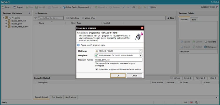
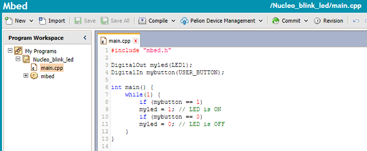
Scroll down and click on “Open Mbed compiler”. As you can see the compiler has already recognized our platform as Nucleo-F401RE and is providing us with a lot of basic example programs. For now, let me select the “LED Blinky code” and modify it so that the LED turns off whenever I press the push button.
Once the code is ready as shown below, you can click on the compile button, which will provide you a bin file, just copy the bin file and paste it in your flash drive to program your board. You will notice the LD1 LED turning Green once programming is complete. Now press the blue button and you will notice the Green LED turning off. Like that you can try any of the example programs to learn different functionalities of the board. You can also go back to the main page to get other technical documents and community support.
You can also watch the video linked at the bottom of this page, to view the complete review on this board.
Conclusion
Overall I believe, these boards are excellent choices if you are trying to level up your skills and develop advanced applications. With its practical hardware support and online community, the learning curve of these boards is also quite simple, so you might want to give it a try. I hope, you enjoyed the article and learned something useful from it. If you have any questions, leave them in the comment section below or use our forums for other technical questions.
