
Raspberry Pi HAT is an add-on board for Raspberry Pi with the same dimensions as Pi. It can directly fit on the top of Raspberry Pi and doesn’t require any further connections. There are hundreds of Raspberry Pi HATs available in the market and we also built Raspberry Pi Hat for 16x2 LCD. In this session we are going to build a LoRa Hat for Raspberry Pi on PCB. This LoRa Hat consists of an SX1278 433MHz LoRa Module, OLED Display Module, and 3.7 to 5V booster circuit. This Raspberry Pi LoRa HAT will come in handy when you have to create a LoRa mesh network or to deploy LoRa sensing nodes.
We have used PCBWay to provide the PCB boards for this project. In the following sections of the article, we have covered in details the complete procedure to design, order, and assemble the PCB boards for Raspberry pi LoRa HAT. Here we are using the LoRa hat to communicate with Arduino.
If you are new to LoRa, then start with the basics of LoRa communication and follow our various tutorials on LoRa technology and its interfacing with a different microcontroller, and peer to peer communication with Arduino.
Components Required
- Raspberry Pi
- SX1278 433MHz LoRa Module
- OLED Display Module
- FP6291 Boost Converter IC
- 3× Resistor (12k, 88k, 48k)
- 6× Capacitor (2×0.1µf, 1×10µf, 2×20µf)
- 1× Inductor (4.7µH)
- 1× Diode (1N5388BRLG)
- 18650 Lithium Cell
- 18650 Cell Holder
- 6-Pin Push Button Switch
Raspberry Pi LoRa HAT Circuit Diagram
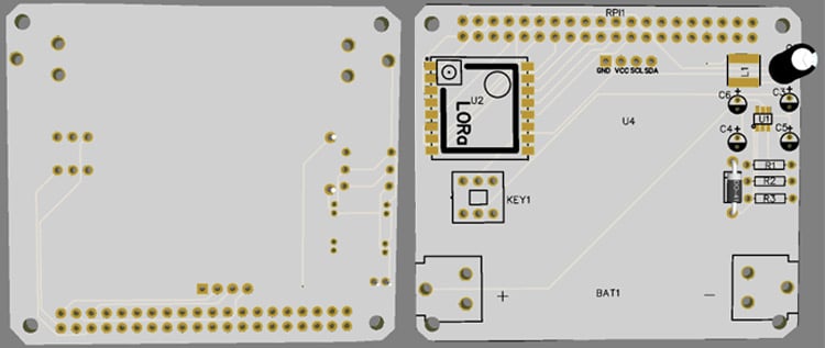
The complete circuit diagram for Raspberry Pi LoRa HAT is shown below. The schematic was drawn using EasyEDA. This HAT consists of the SX1278 433MHz LoRa Module with an OLED Display Module and Booster circuit. Booster circuit is designed around a dedicated FP6291 Boost Converter IC to boost the battery voltage from 3.7v to 5V. The HAT will directly sit on top of Raspberry Pi providing its LoRa capabilities.

FP6291 IC is a 1 MHz DC-DC Step-Up Booster IC, mainly used in the application, for example, getting stable 5V from a 3V battery. You only need a few extra components to design a booster circuit with this IC. Here in this circuit, the Boost Converter circuit gets the input supply through battery terminals (+ and -). This input voltage is then processed by FP6291 IC to give a stable 5V DC supply to the 5V pin of Raspberry Pi.
The output voltage from this IC can be configured using the potential divider circuit. The formula to calculate the output voltage is:
VOUT = 0.6(1+ R1/ R2)
For Arduino connections and circuit diagram, you can check our previous tutorial where the peer to peer LoRa communication between Raspberry Pi and Arduino is explained in detail.
Fabricating PCB for Raspberry Pi LoRa HAT
The schematic is done, and we can proceed with laying out the PCB. You can design the PCB using any PCB software of your choice. We have used EasyEDA to fabricate PCB for this project.
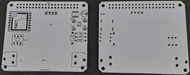
Below are the 3D model views of the top layer and bottom layer of the LoRa HAT:
The PCB layout for the above circuit is also available for download as Gerber from the link given below:
Ordering PCB from PCBWay
Now after finalizing the design, you can proceed with ordering the PCB:
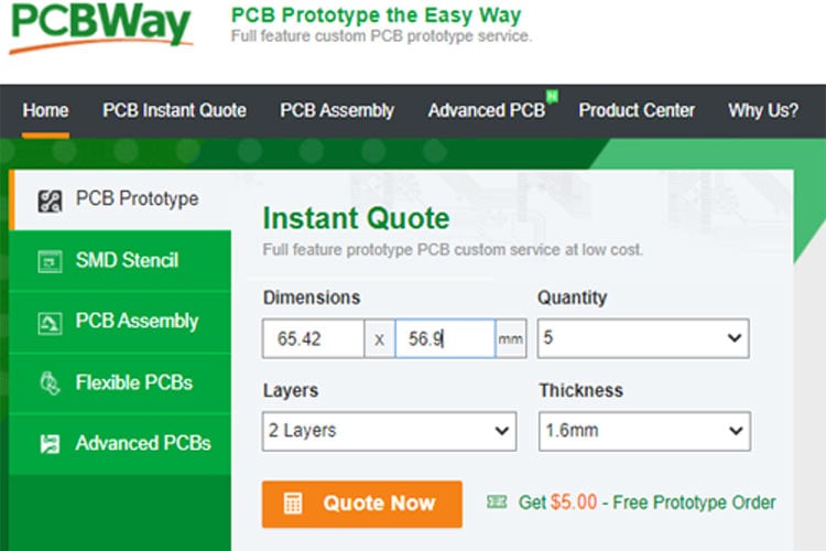
Step 1: Get into https://www.pcbway.com/, sign up if this is your first time. Then, in the PCB Prototype tab, enter the dimensions of your PCB, the number of layers, and the number of PCB you require.
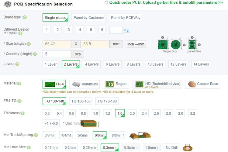
Step 2: Proceed by clicking on the ‘Quote Now’ button. You will be taken to a page where to set a few additional parameters like the Board type, Layers, Material for PCB, Thickness, and More, most of them are selected by default, if you are opting for any specific parameters, you can select it in here.
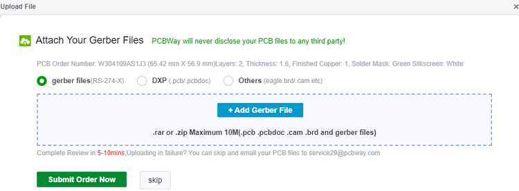
Step 3: The final step is to upload the Gerber file and proceed with the payment. To make sure the process is smooth, PCBWAY verifies if your Gerber file is valid before proceeding with the payment. This way, you can sure that your PCB is fabrication friendly and will reach you as committed.
Assembling the Raspberry Pi LoRa HAT
After a few days, we received our PCB in a neat package and the PCB quality was good as always. The top layer and the bottom layer of the board are shown below.
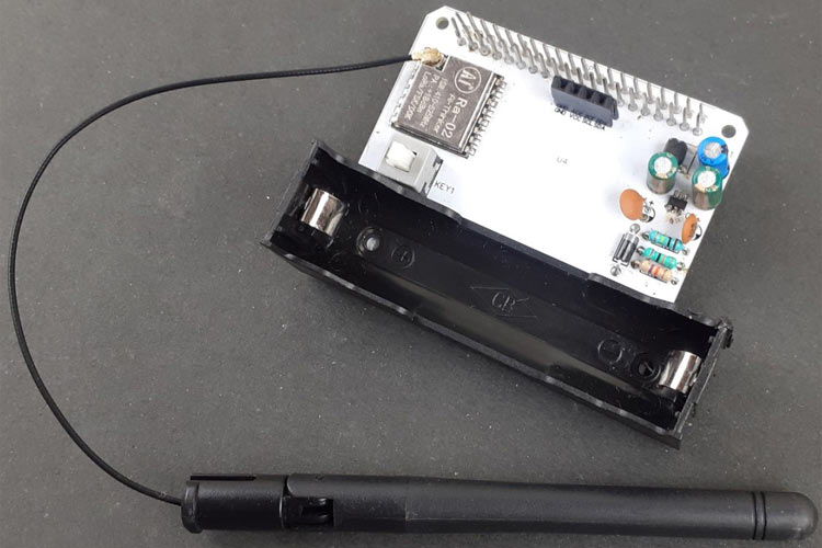
After making sure the tracks and footprints were correct. I proceeded with assembling the PCB. The completely soldered board looks like the below:
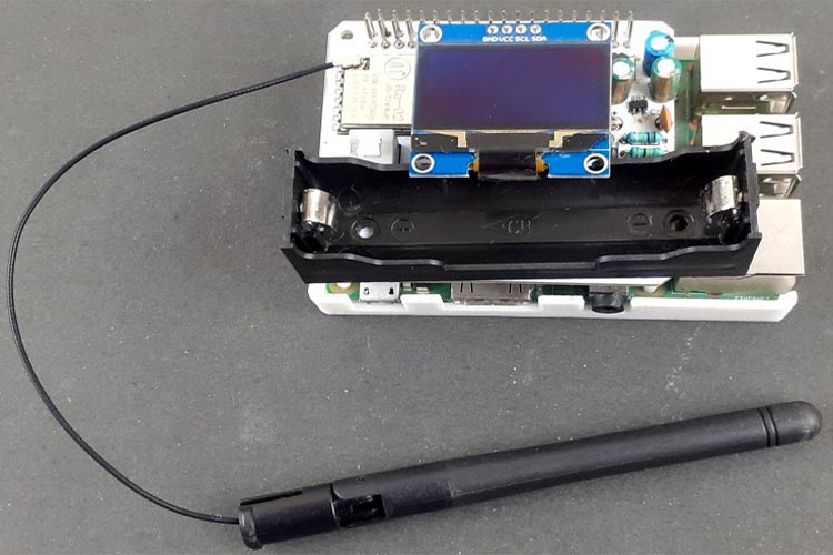
It will look like this after putting OLED on it:
Raspberry Pi Setup for LoRa Hat
Now to test the LoRa HAT for Raspberry Pi, first, we have to program the Raspberry Pi so that it can receive data from LoRa Transmitter and display the vales on OLED Display.
So first update the Raspberry Pi OS using the below commands:
sudo apt-get update
sudo apt-get upgrade
Installing pyLoRa on Pi:
Then use the below command to install the spidev package. Spidev is a python package for Linux which can be used to perform SPI communication on Raspberry Pi.
pip3 install spidev
Now in the next step, install the pyLoRa package using the following pip command. pyLoRa package installs the Radio models associated with LoRa.
pip3 install pyLoRa
Installing luma.oled on Pi:
luma.oled provides a Python3 interface to OLED matrix displays with the SSD1306, SSD1309, SSD1322, SSD1325, SSD1327, SSD1331, SSD1351, SSD1362, SH1106 or WS0010 controllers to connect with Raspberry Pi and other Linux-based single-board computers. For more information and examples, you can visit their website.
Use the below commands to install the luma.oled Dependencies:
sudo apt-get update
sudo apt-get install python3 python3-pip python3-pil libjpeg-dev zlib1g-dev libfreetype6-dev liblcms2-dev libopenjp2-7 libtiff5 -y
sudo -H pip3 install luma.oled
sudo apt-get install python3-imaging
Now in the last step, check if the SPI and I2C interface is enabled or not. For that, enter the below command in the pi terminal and press enter:
sudo raspi-config
Then go to Interfacing Options and enable SPI and I2C Interface if not enabled already.
Programming Raspberry Pi for LoRa Module
Here Raspberry Pi is used as a client and the Arduino as a server. We have previously built the same setup for LoRa communication between Arduino and Raspberry Pi. The complete Raspberry Pi program can be found at the bottom of this page. Here I will try to explain the important lines in the Raspberry Pi program.
So start the code by including all the required packages.
from time import sleep
from SX127x.LoRa import *
from SX127x.board_config import BOARD
from luma.core.interface.serial import i2c, spi, pcf8574
from luma.core.render import canvas
from luma.oled.device import ssd1306, ssd1309, ssd1325, ssd1331, sh1106
from PIL import ImageFont, ImageDraw
Now in the next lines, create a python LoRa class with three definitions. These three definitions are the init class, start class, and on_rx_done class. The init class is used to initialize the LoRa module in 433MHz with 125kHz bandwidth. It initializes it in sleep mode to save power consumption.
def __init__(self, verbose=False):
        super(LoRaRcvCont, self).__init__(verbose)
        self.set_mode(MODE.SLEEP)
        self.set_dio_mapping([0] * 6)
The start function is used to configure the module as a receiver and obtain like RSSI status, operating frequency, etc. We set the module to work in continuous receiver mode (RXCONT) from sleep mode and then use a while loop to read values like RSSI and modem status.
def start(self):
        self.reset_ptr_rx()
        self.set_mode(MODE.RXCONT)
        while True:
            sleep(.5)
            rssi_value = self.get_rssi_value()
            status = self.get_modem_status()
            sys.stdout.flush()
Finally, the on_rx_done function is used to receive the data packet. The received values then moved into a variable called payload from the Rx buffer. Then the received values are decoded with utf-8 to print user-readable data on the shell.
def on_rx_done(self):
        print ("\nReceived: ")
        self.clear_irq_flags(RxDone=1)
        payload = self.read_payload(nocheck=True
        #print (bytes(payload).decode("utf-8",'ignore'))
        data = bytes(payload).decode("utf-8",'ignore')
Now print the received data on OLED Display. Here I am using 'arial.ttf' font on the OLED display. To use a different font, then default font in luma.oled library, you have to download the font and then put it into the same folder as code. You can download the ‘arial.ttf’ font from here.
        data1 = data[2:9]
        print(data1)
        with canvas(device) as draw:
          font = ImageFont.load_default()
          font = ImageFont.truetype('arial.ttf',18)
          draw.text((10, 17), "Received:", font=font, fill="white")
          draw.text((25, 40),data1,font=font,fill="white")
The complete Arduino code is given at the end of the page. You can also follow this Raspberry Pi - Arduino LoRa communication tutorial for circuit diagram and other information.
Testing the Raspberry Pi LoRa HAT
Now, that both Arduino and Raspberry Pi codes are ready, simply have to upload the Arduino code to the UNO board and launch the Python sketch in Raspberry Pi.
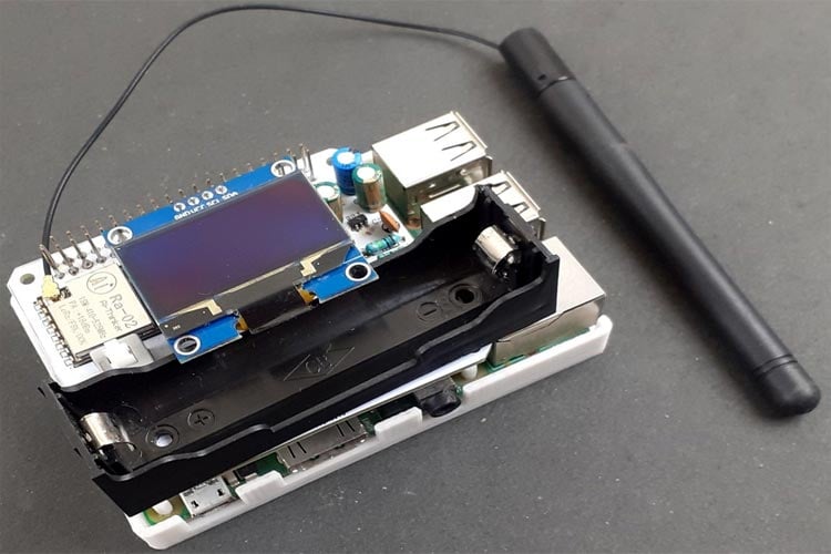
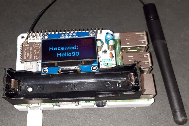
If the code uploads successfully, you should see the Arduino packets received in pi through the OLED Display as shown in the below image:
Hope you enjoyed the article and learned something useful. If you have any questions, you can leave them in the comment section below or use our forums for other technical questions.
Complete Project Code
from time import sleep
from SX127x.LoRa import *
from SX127x.board_config import BOARD
from luma.core.interface.serial import i2c, spi, pcf8574
from luma.core.render import canvas
from luma.oled.device import ssd1306, ssd1309, ssd1325, ssd1331, sh1106
from PIL import ImageFont, ImageDraw
serial = i2c(port=1, address=0x3C)
device = sh1106(serial)
BOARD.setup()
class LoRaRcvCont(LoRa):
    def __init__(self, verbose=False):
        super(LoRaRcvCont, self).__init__(verbose)
        self.set_mode(MODE.SLEEP)
        self.set_dio_mapping([0] * 6)
    def start(self):
        self.reset_ptr_rx()
        self.set_mode(MODE.RXCONT)
        while True:
            sleep(.5)
            rssi_value = self.get_rssi_value()
            status = self.get_modem_status()
            sys.stdout.flush()
    def on_rx_done(self):
        print ("\nReceived: ")
        self.clear_irq_flags(RxDone=1)
        payload = self.read_payload(nocheck=True)
        print (payload)
        data = bytes(payload).decode("utf-8",'ignore')
        data1 = data[2:9]
        print(data1)
        with canvas(device) as draw:
          device.clear()
          font = ImageFont.load_default()
          font = ImageFont.truetype('arial.ttf',18)
          draw.text((10, 17), "Received:", font=font, fill="white")
          draw.text((30, 40),data1,font=font,fill="white")
          device.clear()
        self.set_mode(MODE.SLEEP)
        self.reset_ptr_rx()
        self.set_mode(MODE.RXCONT)
lora = LoRaRcvCont(verbose=False)
lora.set_mode(MODE.STDBY)
#  Medium Range  Defaults after init are 434.0MHz, Bw = 125 kHz, Cr = 4/5, Sf = 128chips/symbol, CRC on 13 dBm
lora.set_pa_config(pa_select=1)
try:
    lora.start()
except KeyboardInterrupt:
    sys.stdout.flush()
    print ("")
    sys.stderr.write("KeyboardInterrupt\n")
finally:
    sys.stdout.flush()
    print ("")
    lora.set_mode(MODE.SLEEP)
    BOARD.teardown()