
Raspberry Pi Hats are the same as shields for Arduino, they can directly fit on the top of Raspberry Pi and don’t require any further connections. Here we are going to build an RGB LCD Hat for Raspberry Pi on PCB. This LCD Hat consists of a 16x2 LCD module, five switches, and three NeoPixel LEDs. Here switches are used to change the text on display and NeoPixel LEDs are used as indicators. These switches and Neo Pixels can be programmed according to requirements like switches can be used to display sensor values like temperature, humidity, etc. and Neo pixels can be used to display status like Red for indicating some error and green while receiving some data.
Here we will use EasyEDA online software to design the circuit and PCB for this Pi HAT, and JLCPCB to order the PCBs.
Components Required
- Raspberry Pi 4
- 16*2 LCD Display Module
- Neo-pixel LEDs (3)
- Capacitors
- Switches (5)
Circuit Diagram
The complete circuit diagram for Raspberry Pi RGB LCD HAT is shown below. The schematic was drawn using EasyEDA. As you can see, we are interfacing a 16x2 LCD module, 3 NeoPixel LEDs and 5 Switches with Raspberry Pi. A connector is also used to enable or disable the NeoPixel LEDs.

Fabricating PCB for Raspberry Pi RGB LCD HAT using EasyEDA
While designing the PCB for Raspberry Pi RGB LCD HAT, the most challenging part was getting the footprint right. If the dimensions go wrong, then the components will not fit on PCB. But lucky enough, EasyEDA provides footprints for almost all components in the market. This is because of its vast user community where users create footprints and make it available for the public to use it in their projects.
EasyEDA is an online EDA tool that I have previously used many times and found it very convenient to use since it has a good collection of footprints, and it is open-source. After designing the PCB, we can order the PCB samples by their low-cost PCB fabrication services- JLCPCB. They also offer component sourcing services where they have a large stock of electronic components, and users can order their required components along with the PCB order.
While designing the circuits and PCBs, you can also make your circuit, and PCB designs public so that other users can copy or edit them and can take benefit from your work, we have also made this Pi RGB LCD Hat design public, check the below link:
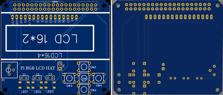
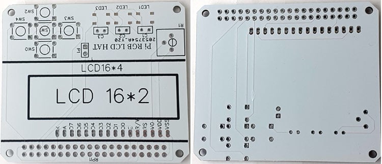
You can view any Layer (Top, Bottom, Topsilk, bottom silk, etc.) of the PCB by selecting the layer form the ‘Layers’ window. Apart from this, they also provide a 3D model view of the PCB on how it would appear after fabrication. The snapshot of the top layer and bottom layer of the LCD HAT would look something like this:
Calculating and Ordering PCB Samples online using EasyEDA
After completing the design of this PI RGB LCD HAT, you can order the PCB through JLCPCB.com. To order the PCB from JLCPCB, you need Gerber File. You can download the Gerber file from the link below:
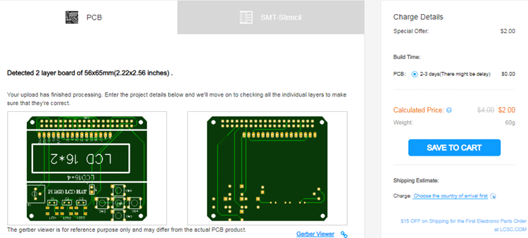
To generate the Gerber files of the PCB, just click the Generate Fabrication File button on the EasyEDA editor page, then download the Gerber file from there, or click on Order at JLCPCB as shown in below image. This will redirect you to JLCPCB.com, where you can select the number of PCBs to order, how many copper layers you need, PCB thickness, copper weight, PCB color, and other PCB parameters, like the snapshot shown below:
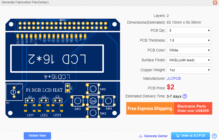
After clicking on the ‘Order at JLCPCB’ button, it will take you to the JLCPCB website, where you can order the PCB at a very low rate, which is $2. Their build time is also very less, which is 48 hours with DHL delivery of 3-5 days. You will get your PCBs within a week of ordering.
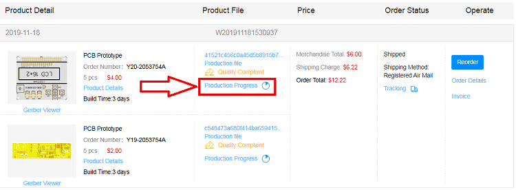
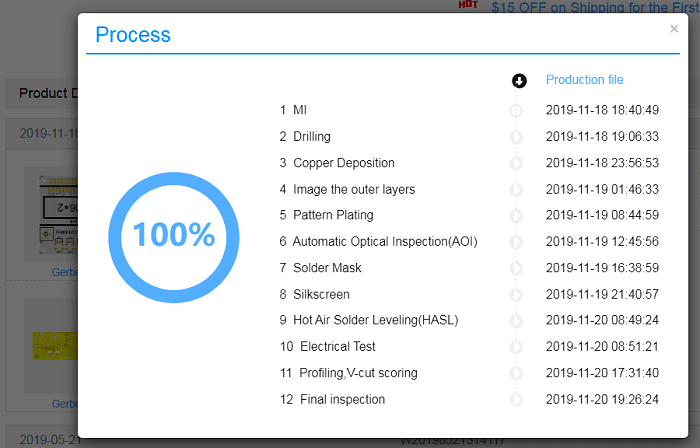
After ordering the PCB, you can check the Production Progress of your PCB with date and time. You can check it by going on the Account page and click on the "Production Progress" link under the PCB like shown in the below image.
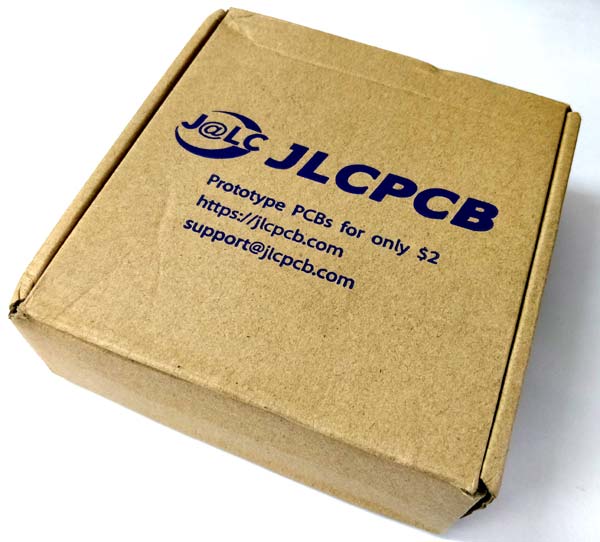
After a few days of ordering PCBs, I got the PCB samples in excellent packaging, as shown in the below pictures.
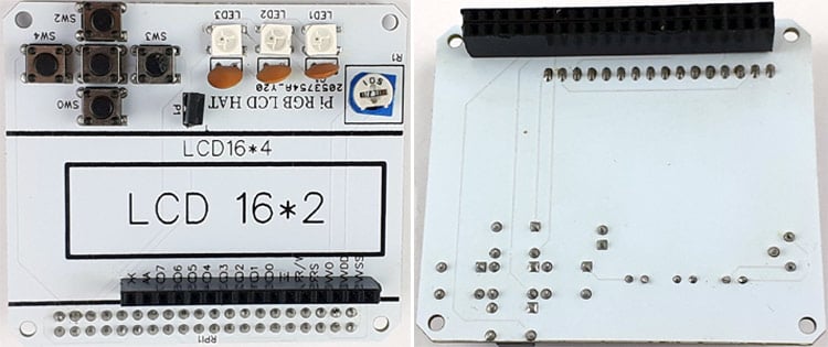
After making sure the tracks and footprints were correct. I proceeded with assembling the PCB. The completely soldered board looks like the below:
Raspberry Pi Setup for LCD Hat
Before start programming, the Raspberry Pi, first update the Raspberry Pi and install a few necessary libraries. Run below commands to update and upgrade Raspberry Pi:
sudo apt-get update
sudo apt-get upgrade
Now install the Adafruit_Blinka library for NeoPixel LEDs. Adafruit_Blinka library provides the CircuitPython support in Python.
sudo pip3 install adafruit-circuitpython-neopixel
After that, install the Adafruit_CharLCD library for the LCD module. This library is for Adafruit LCD boards, but it also works with other brand LCD boards as well.
sudo pip3 install Adafruit-CharLCD
Python Code for Raspberry Pi LCD HAT
Here we are demonstrating the RGB LCD hat for Raspberry Pi by using few switches to show some particular values on the LCD module and RGB LEDs as indicators. So we have to program the Raspberry Pi in a way that when we press a Switch, it should show some sensor values or other values.
Complete python code is given at the end of the page. Here we are explaining the code step by step.
Start the code by importing all the required libraries.
import RPi.GPIO as GPIO
import neopixel
import time
import board
import Adafruit_CharLCD as LCD
After that, define all the GPIO pins where the LCD and other switches are connected.
lcd_rs = 7
lcd_en = 8
lcd_d4 = 25
lcd_d5 = 24
lcd_d6 = 23
lcd_d7 = 18
lcd_backlight = 2
sw0 = 5
sw2 = 13
sw3 = 19
sw4 = 26
Now, define the GPIO mode using BCM mode. You can also change it to BOARD. Then define all the switch pins as Inputs.
GPIO.setmode(GPIO.BCM)       # Use BCM GPIO numbers
GPIO.setup(sw0 , GPIO.IN)
GPIO.setup(sw2 , GPIO.IN)
GPIO.setup(sw3, GPIO.IN)
GPIO.setup(sw4, GPIO.IN)
After that, define the GPIO pin where the Neo Pixel LEDs are connected. Then define the no of Neo Pixel LEDs. Here three LEDs are used, you can change it according to your needs.
pixel_pin = board.D21
num_pixels = 3
Now inside the lcddisplay() function, assign a particular task to each switch. For example, here when the first switch is pressed, Raspberry Pi should display ‘UP’ on LCD, and when the second switch is pressed, it should display ‘DOWN’ on the LCD and so on for the other two buttons.
Instead of printing something on an LCD, you can use these Switches to perform a different task. For example, you can use switch1 to display Temperature value, switch2 to display Humidity values, and switch 3 to display Pressure values, etc.
def lcddisplay():
    if ( GPIO.input(sw0) == False):
      lcd.clear()
      lcd.set_cursor(0,0 )
      lcd.message ('UP')
    if ( GPIO.input(sw2) == False):
      lcd.clear()
      lcd.set_cursor(0,0 )
      lcd.message ('DOWN')
    if ( GPIO.input(sw3) == False):
      lcd.clear()
      lcd.set_cursor(0,0 )
      lcd.message ('LEFT')
    if ( GPIO.input(sw4) == False):
      lcd.clear()
      lcd.set_cursor(0,0 )
      lcd.message ('RIGHT')
Now inside the while true loop, pixels.fill function is used to light up the Neo Pixels in different colors. So the Pi is programmed to light up the Neo Pixels with Red Green and Blue color for one second each.
You can also use these Neo Pixels as indicators. For example, you can light up one Neo Pixel with Red color to indicate that the Pi is connected to the power source or you can use other LEDs to indicate that the Pi is receiving or sending the Data, etc.
pixels.fill((255, 0, 0))
pixels.show()
time.sleep(1)
pixels.fill((0, 255, 0))
pixels.show()
time.sleep(1)
pixels.fill((0, 0, 255))
pixels.show()
time.sleep(1)
rainbow_cycle(0.001)
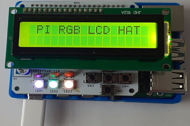
Testing the Raspberry Pi RGB LCD HAT
After assembling the LCD and interfacing it with Raspberry Pi, we are all set to use this PI RGB LCD HAT. For that, run the python code by using the below command.
python code_filename.py
Now press the switches. When you press the SW0 switch, it should print ‘UP’ on the LCD. For the SW2 switch, it should print ‘Down’ and the same for the rest of the switches.
A complete working video along with Python code is given below.
Complete Project Code
import RPi.GPIO as GPIO

import neopixel

import time

import board

import Adafruit_CharLCD as LCD

# Raspberry Pi pin setup

lcd_rs = 7

lcd_en = 8

lcd_d4 = 25

lcd_d5 = 24

lcd_d6 = 23

lcd_d7 = 18

lcd_backlight = 2

sw0 = 5

sw2 = 13

sw3 = 19

sw4 = 26

# Define LCD column and row size for 16x2 LCD.

lcd_columns = 16

lcd_rows = 2

lcd = LCD.Adafruit_CharLCD(lcd_rs, lcd_en, lcd_d4, lcd_d5, lcd_d6, lcd_d7, lcd_columns, lcd_rows, lcd_backlight)

GPIO.setmode(GPIO.BCM)       # Use BCM GPIO numbers

GPIO.setup(sw0 , GPIO.IN)

GPIO.setup(sw2 , GPIO.IN)

GPIO.setup(sw3, GPIO.IN)

GPIO.setup(sw4, GPIO.IN)

#board.NEOPIXEL

pixel_pin = board.D21

 # The number of NeoPixels

num_pixels = 3

# The order of the pixel colors - RGB or GRB. Some NeoPixels have red and green reversed!

# For RGBW NeoPixels, simply change the ORDER to RGBW or GRBW.

ORDER = neopixel.RGB

pixels = neopixel.NeoPixel(pixel_pin, num_pixels, brightness=0.2, auto_write=False, pixel_order=ORDER)

lcd.set_cursor(1,0 )

lcd.message  ('PI RGB LCD HAT ')

def lcddisplay():

    if ( GPIO.input(sw0) == False):

      lcd.clear()

      lcd.set_cursor(0,0 )

      lcd.message ('UP')

    if ( GPIO.input(sw2) == False):

      lcd.clear()

      lcd.set_cursor(0,0 )

      lcd.message ('DOWN')

    if ( GPIO.input(sw3) == False):

      lcd.clear()

      lcd.set_cursor(0,0 )

      lcd.message ('LEFT')

    if ( GPIO.input(sw4) == False):

      lcd.clear()

      lcd.set_cursor(0,0 )

      lcd.message ('RIGHT')

def wheel(pos):

    # Input a value 0 to 255 to get a color value.

    # The colours are a transition r - g - b - back to r.

    if pos < 0 or pos > 255:

        r = g = b = 0

    elif pos < 85:

        r = int(pos * 3)

        g = int(255 - pos*3)

        b = 0

    elif pos < 170:

        pos -= 85

        r = int(255 - pos*3)

        g = 0

        b = int(pos*3)

    else:

        pos -= 170

        r = 0

        g = int(pos*3)

        b = int(255 - pos*3)

    return (r, g, b) if ORDER == neopixel.RGB or ORDER == neopixel.GRB else (r, g, b, 0)

def rainbow_cycle(wait):

    for j in range(255):

        for i in range(num_pixels):

            pixel_index = (i * 256 // num_pixels) + j

            pixels[i] = wheel(pixel_index & 255)

        pixels.show()

        time.sleep(wait)

while True:

    lcddisplay()

    # Comment this line out if you have RGBW/GRBW NeoPixels

    pixels.fill((255, 0, 0))

    # Uncomment this line if you have RGBW/GRBW NeoPixels

    # pixels.fill((255, 0, 0, 0))

    pixels.show()

    time.sleep(1)

    # Comment this line out if you have RGBW/GRBW NeoPixels

    pixels.fill((0, 255, 0))

    # Uncomment this line if you have RGBW/GRBW NeoPixels

    # pixels.fill((0, 255, 0, 0))

    pixels.show()

    time.sleep(1)

    # Comment this line out if you have RGBW/GRBW NeoPixels

    pixels.fill((0, 0, 255))

    # Uncomment this line if you have RGBW/GRBW NeoPixels

    # pixels.fill((0, 0, 255, 0))

    pixels.show()

    time.sleep(1)

    rainbow_cycle(0.001)    # rainbow cycle with 1ms delay per step
