

When soldering, sometimes the need arises to control the temperature of the soldering iron, especially, for micro soldering or any other precision soldering job. It is important to keep the temperature under control because overheating may damage sensitive semiconductor parts. That is where a temperature-controlled soldering station comes to play. But the problem is that these are not cheap and not affordable for many hobbyists. The cheap ones available in the market are either of low quality or can’t be trusted with their temperature reading and stabilization. So, in this tutorial, we are going to build a soldering station with temperature controller along with some exciting features.

Soldering Iron Controller Features
- Accurate temperature readings
- PID control for better temperature stabilization
- Easy control with a single rotary encoder.
- Easy to use UI with OLED Display
- Boost mode for quick temperature increase
- Handle movement detection
- Handle to-tip disconnect error
- Sleep Mode
- Auto Power-off
- Input Voltage Measurement
- Buzzer for audio indication
- Multiple Tip Profiles
- Screen rotation
- Encoder direction change
- Buzzer On/Off
Components Required to build Digital Soldering Iron Controller
- ATMEGA328P-AU x1
- IRLR7843 MOSFET x1
- 78M05 x1
- LMV358IDR x1
- 16MHZ Crystal /Resonator x1
- 128x64 0.96” OLED x1
- SS34 Diode x1
- 1N4148W Diode x1
- 5V1 Zener Diode x1
- 18V Zener Diode x1
- S8050 Transistor SOT-23 x1
- 3x6x2.5 SMD Switch
- Rotary Encoder EC11
- MLT-5030 SMD Buzzer x1
- 100n 0603 Capacitor x5
- 47u 1206 Capacitor x1
- 22p 0603 Capacitor x2
- 10u 1206 Capacitor x1
- 2n2 0603 Capacitor x1
- 330n 0603 Capacitor x1
- 22u 1206 Capacitor x1
- 1u 0603 Capacitor x1
- 10k 0603 Resistor x9
- 1k5 0603 Resistor x1
- 1k 0603 Resistor x1
- 200k 0603 Resistor x1
- 1k 1206 Resistor x1
- 47k 0603 Resistor x1
Soldering Iron Controller Circuit Diagram
The complete circuit diagram for the OLED Soldering Station Controller is given below.

ATMEGA328P is used as the controller here. Not only they are easily available but also make programming easy by using the Arduino IDE. Here the ATMEGA328 is running at 16MHz with a supply voltage of 5V. Pin A0 is used to read the temperature from the thermocouple amplifier, pin A1 is used to read the input, Pins A4 and A5 are used for the I2C lines for the OLED, Pin D5 is used for the buzzer, Pins D6, D7, and D8 are used to read the encoder and the pins D9 and D10 are used for driving mosfet and to read the handle tilt switch respectively.
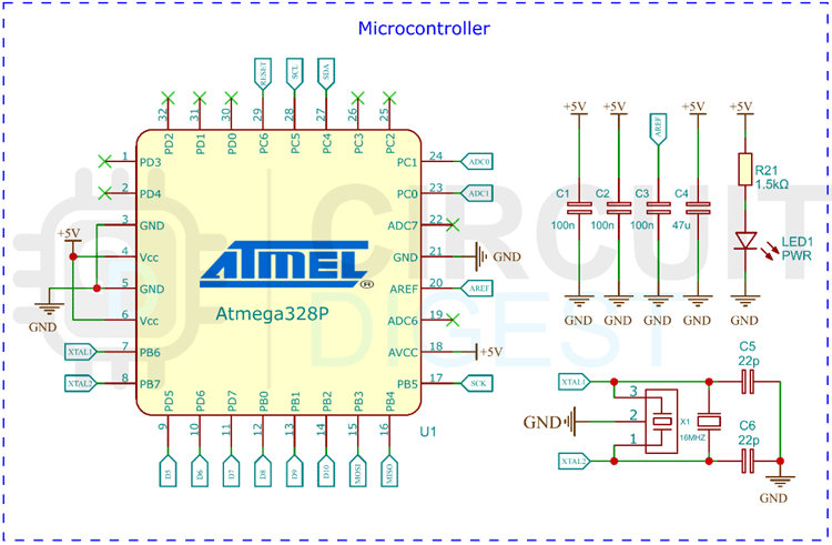
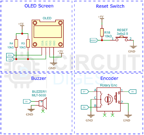
A 0.96” OLED with a resolution of 128x64 pixels is used as the display for the controller. This will make the UI much easier, more attractive and user-friendly. We are using the OLED with the I2C protocol. An SMD buzzer is also added to the PCB for audible indications. It can be enabled or disabled within the menu. An EC11 rotary encoder is used to control the soldering controller. It makes it easier to navigate through menu or increase temperature without any hustle.
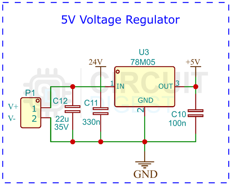
The 5V for the controller circuit is generated using the popular 7805 linear voltage regulator. Since the whole circuit will only consume less than 50mA, there is no need to use any buck converter for the job. We have added all the necessary filer capacitors to the regulator to reduce and noise.
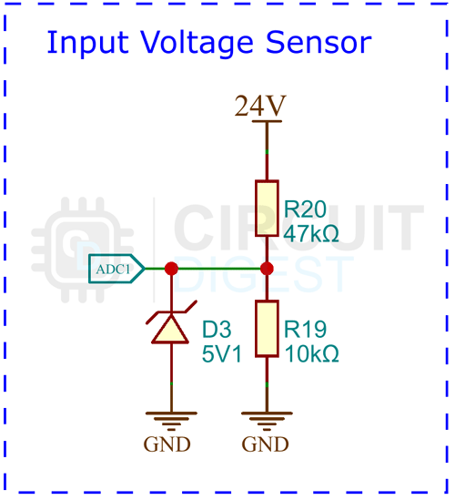
The input voltage is measured using the classic voltage divider circuit. The voltage divider will allow us to measure the higher input voltages. A 5.1v Zener diode is used as a protection for the ADC pin in case of any voltage spike or accidental over voltage.
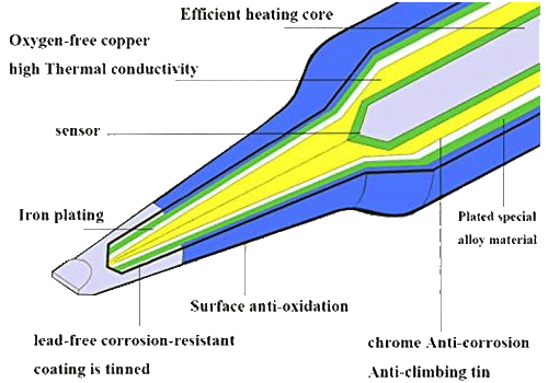
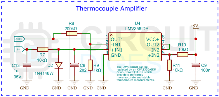
The thermocouple amplifier is built around the famous LM358 OP-AMP chip. A thermocouple (temperature sensor) is located in the T12 soldering tip. It creates a very small voltage depending on the temperature difference between the hot end and the cold junction (about 40 microvolts per degree Celsius). To measure this, the heater must be switched off since both share the same connections. Here is the internal structure of a T12 or T15 tip.
The low voltage is amplified by the OpAmp and measured by the ADC of the microcontroller. The LMV358 is a very cheap and versatile OpAmp, but not the ideal choice for this task because it has a fairly high input offset voltage and is quite noisy. Although the Soldering Station also works with this Op-Amp thanks to the software's smoothing and calibration algorithms, I highly recommend spending a little more money on a better one. The OPA2330AIDR or OPA2333AIDR for instance have the same pinout and can also be used with this board. They provide significantly more accurate and stable temperature measurements.
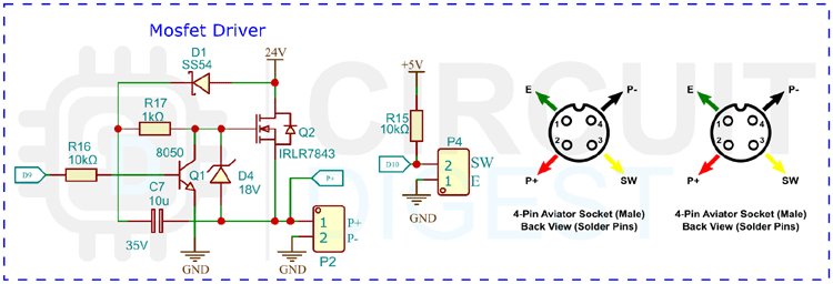
The microcontroller switches the heater on and off via the MOSFET. Since the temperature measurement must be done over the same line and against the ground, the MOSFET has to be placed between the supply voltage and the heater (high-side switch). A P-Channel MOSFET is normally used for this configuration. However, N-Channel MOSFETs usually have a lower resistance (RDS (on)) and are cheaper than their P-Channel counterparts. Low resistance means higher efficiency and lower heat development of the MOSFET. For an N-channel MOSFET to function as a high-side switch, an additional circuit is required to maintain a positive GATE-TO-SOURCE voltage after the MOSFET is switched on. This is done using a so-called charge pump circuit consisting of a capacitor and a diode.
Testing DIY Soldering Station
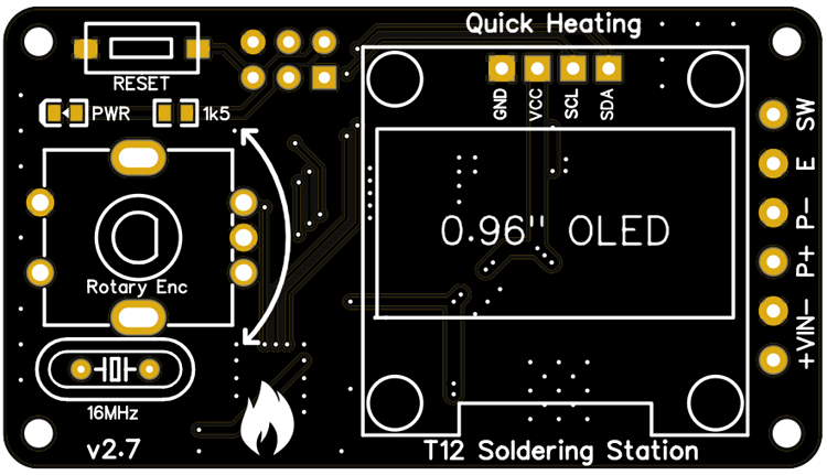
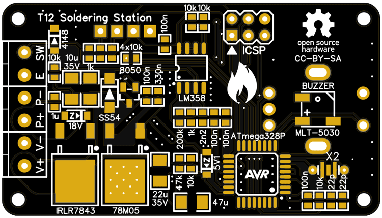
You can either build this project in a perf board or make a PCB with the files from the link at the bottom of the page. This project is based on the project by Stefan Wagner. Gerber files for the manufacturing are included. Here is the PCB layout for the Soldering controller.
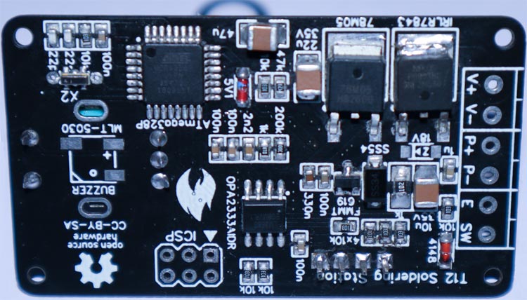
Here is the bottom side PCB view-
Here is the fully assembled PCB-
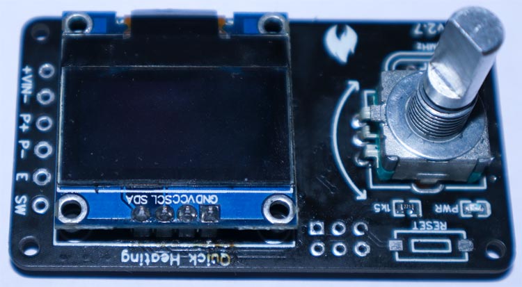
And here is the fully-assembled unit-
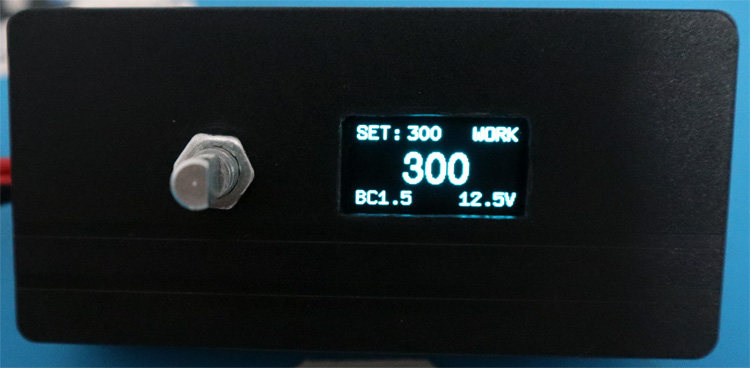
I have used a generic power supply unit case as the enclosure. You can choose whichever enclosure is more suitable for you.
Here are the connections for the T12 tips.
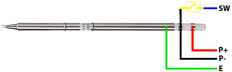
You can use T12 handles or the 907 handles with the controller. A tilt switch is used to detect motion. You can use either mercury-based or the spring-based tilt switch.
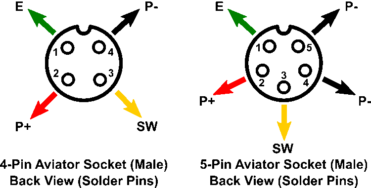
And here is the aviator connector pinout if you are interested in using them.
Arduino Code for Soldering Controller
Download the entire code from the Circuit Digest GitHub repo link given at the bottom of this article. All the necessary libraries are included in the repo. Download the files and extract them to a folder. Open the .ino file in the Arduino IDE and select Arduino Nano as the board from the board manager. Then compile the code and upload it using the ISP connector in the PCB. That’s it our Soldering Controller is ready to use. If the temperature is wrong, you can calibrate it using the calibration option in the Tip setting.
You can download all the necessary files from the Circuit Digest GitHub repo, from the following link.


Complete Project Code
#include "src/U8glib.h"
#include "src/PID_v1.h"
#include <EEPROM.h>             // for storing user settings into EEPROM
#include <avr/sleep.h>          // for sleeping during ADC sampling
// Firmware version
#define VERSION       "v1.9"
// Type of MOSFET
#define N_MOSFET                // P_MOSFET or N_MOSFET
// Type of OLED Controller
#define SSD1306                 // SSD1306 or SH1106
// Type of rotary encoder
#define ROTARY_TYPE   1         // 0: 2 increments/step; 1: 4 increments/step (default)
// Pins
#define SENSOR_PIN    A0        // tip temperature sense
#define VIN_PIN       A1        // input voltage sense
#define BUZZER_PIN     5        // buzzer
#define BUTTON_PIN     6        // rotary encoder switch
#define ROTARY_1_PIN   7        // rotary encoder 1
#define ROTARY_2_PIN   8        // rotary encoder 2
#define CONTROL_PIN    9        // heater MOSFET PWM control
#define SWITCH_PIN    10        // handle vibration switch
// Default temperature control values (recommended soldering temperature: 300-380°C)
#define TEMP_MIN      150       // min selectable temperature
#define TEMP_MAX      400       // max selectable temperature
#define TEMP_DEFAULT  320       // default start setpoint
#define TEMP_SLEEP    150       // temperature in sleep mode
#define TEMP_BOOST     50       // temperature increase in boost mode
#define TEMP_STEP      10       // rotary encoder temp change steps
// Default tip temperature calibration values
#define TEMP200       216       // temperature at ADC = 200
#define TEMP280       308       // temperature at ADC = 280
#define TEMP360       390       // temperature at ADC = 360
#define TEMPCHP       30        // chip temperature while calibration
#define TIPMAX        8         // max number of tips
#define TIPNAMELENGTH 6         // max length of tip names (including termination)
#define TIPNAME       "BC1.5"   // default tip name
// Default timer values (0 = disabled)
#define TIME2SLEEP     5        // time to enter sleep mode in minutes
#define TIME2OFF      15        // time to shut off heater in minutes
#define TIMEOFBOOST   40        // time to stay in boost mode in seconds
// Control values
#define TIME2SETTLE   950       // time in microseconds to allow OpAmp output to settle
#define SMOOTHIE      0.05      // OpAmp output smooth factor (1=no smoothing; 0.05 default)
#define PID_ENABLE    false     // enable PID control
#define BEEP_ENABLE   true      // enable/disable buzzer
#define BODYFLIP      false     // enable/disable screen flip
#define ECREVERSE     false     // enable/disable rotary encoder reverse
#define MAINSCREEN    0         // type of main screen (0: big numbers; 1: more infos)
// EEPROM identifier
#define EEPROM_IDENT  0xE76C   // to identify if EEPROM was written by this program
// MOSFET control definitions
#if defined (P_MOSFET)         // P-Channel MOSFET
  #define HEATER_ON   255
  #define HEATER_OFF  0
  #define HEATER_PWM  255 - Output
#elif defined (N_MOSFET)       // N-Channel MOSFET
  #define HEATER_ON   0
  #define HEATER_OFF  255
  #define HEATER_PWM  Output
#else
  #error Wrong MOSFET type!
#endif
// Define the aggressive and conservative PID tuning parameters
double aggKp=11, aggKi=0.5, aggKd=1;
double consKp=11, consKi=3, consKd=5;
// Default values that can be changed by the user and stored in the EEPROM
uint16_t  DefaultTemp = TEMP_DEFAULT;
uint16_t  SleepTemp   = TEMP_SLEEP;
uint8_t   BoostTemp   = TEMP_BOOST;
uint8_t   time2sleep  = TIME2SLEEP;
uint8_t   time2off    = TIME2OFF;
uint8_t   timeOfBoost = TIMEOFBOOST;
uint8_t   MainScrType = MAINSCREEN;
bool      PIDenable   = PID_ENABLE;
bool      beepEnable  = BEEP_ENABLE;
bool      BodyFlip    = BODYFLIP;
bool      ECReverse   = ECREVERSE;
// Default values for tips
uint16_t  CalTemp[TIPMAX][4] = {TEMP200, TEMP280, TEMP360, TEMPCHP};
char      TipName[TIPMAX][TIPNAMELENGTH] = {TIPNAME};
uint8_t   CurrentTip   = 0;
uint8_t   NumberOfTips = 1;
// Menu items
const char *SetupItems[]       = { "Setup Menu", "Tip Settings", "Temp Settings",
                                   "Timer Settings", "Control Type", "Main Screen",
                                   "Buzzer", "Screen Flip", "EC Reverse", "Information", "Return" };
const char *TipItems[]         = { "Tip:", "Change Tip", "Calibrate Tip",
                                   "Rename Tip", "Delete Tip", "Add new Tip", "Return" };
const char *TempItems[]        = { "Temp Settings", "Default Temp", "Sleep Temp",
                                   "Boost Temp", "Return" };
const char *TimerItems[]       = { "Timer Settings", "Sleep Timer", "Off Timer",
                                   "Boost Timer", "Return" };
const char *ControlTypeItems[] = { "Control Type", "Direct", "PID" };
const char *MainScreenItems[]  = { "Main Screen", "Big Numbers", "More Infos" };
const char *StoreItems[]       = { "Store Settings ?", "No", "Yes" };
const char *SureItems[]        = { "Are you sure ?", "No", "Yes" };
const char *BuzzerItems[]      = { "Buzzer", "Disable", "Enable" };
const char *FlipItems[]        = { "Screen Flip", "Disable", "Enable" };
const char *ECReverseItems[]   = { "EC Reverse", "Disable", "Enable" };
const char *DefaultTempItems[] = { "Default Temp", "\xB0""C" };
const char *SleepTempItems[]   = { "Sleep Temp", "\xB0""C" };
const char *BoostTempItems[]   = { "Boost Temp", "\xB0""C" };
const char *SleepTimerItems[]  = { "Sleep Timer", "Minutes" };
const char *OffTimerItems[]    = { "Off Timer", "Minutes" };
const char *BoostTimerItems[]  = { "Boost Timer", "Seconds" };
const char *DeleteMessage[]    = { "Warning", "You cannot", "delete your", "last tip!" };
const char *MaxTipMessage[]    = { "Warning", "You reached", "maximum number", "of tips!" };

// Variables for pin change interrupt
volatile uint8_t  a0, b0, c0, d0;
volatile bool     ab0;
volatile int      count, countMin, countMax, countStep;
volatile bool     handleMoved;

// Variables for temperature control
uint16_t  SetTemp, ShowTemp, gap, Step;
double    Input, Output, Setpoint, RawTemp, CurrentTemp, ChipTemp;

// Variables for voltage readings
uint16_t  Vcc, Vin;

// State variables
bool      inSleepMode = false;
bool      inOffMode   = false;
bool      inBoostMode = false;
bool      inCalibMode = false;
bool      isWorky     = true;
bool      beepIfWorky = true;
bool      TipIsPresent= true;

// Timing variables
uint32_t  sleepmillis;
uint32_t  boostmillis;
uint32_t  buttonmillis;
uint8_t   goneMinutes;
uint8_t   goneSeconds;
uint8_t   SensorCounter = 255;

// Specify variable pointers and initial PID tuning parameters
PID ctrl(&Input, &Output, &Setpoint, aggKp, aggKi, aggKd, REVERSE);

// Setup u8g object depending on OLED controller
#if defined (SSD1306)
  U8GLIB_SSD1306_128X64 u8g(U8G_I2C_OPT_DEV_0|U8G_I2C_OPT_NO_ACK|U8G_I2C_OPT_FAST);
#elif defined (SH1106)
  U8GLIB_SH1106_128X64 u8g(U8G_I2C_OPT_FAST|U8G_I2C_OPT_NO_ACK);
#else
  #error Wrong OLED controller type!
#endif
void setup() {
  // set the pin modes
  pinMode(SENSOR_PIN,   INPUT);
  pinMode(VIN_PIN,      INPUT);
  pinMode(BUZZER_PIN,   OUTPUT);
  pinMode(CONTROL_PIN,  OUTPUT);
  pinMode(ROTARY_1_PIN, INPUT_PULLUP);
  pinMode(ROTARY_2_PIN, INPUT_PULLUP);
  pinMode(BUTTON_PIN,   INPUT_PULLUP);
  pinMode(SWITCH_PIN,   INPUT_PULLUP);

  analogWrite(CONTROL_PIN, HEATER_OFF); // this shuts off the heater
  digitalWrite(BUZZER_PIN, LOW);        // must be LOW when buzzer not in use

  // setup ADC
  ADCSRA |= bit (ADPS0) | bit (ADPS1) | bit (ADPS2);  // set ADC prescaler to 128
  ADCSRA |= bit (ADIE);                 // enable ADC interrupt
  interrupts ();                        // enable global interrupts

  // setup pin change interrupt for rotary encoder
  PCMSK0 = bit (PCINT0);                // Configure pin change interrupt on Pin8
  PCICR  = bit (PCIE0);                 // Enable pin change interrupt
  PCIFR  = bit (PCIF0);                 // Clear interrupt flag

  // prepare and start OLED
  if      ( u8g.getMode() == U8G_MODE_R3G3B2 )   u8g.setColorIndex(255);
  else if ( u8g.getMode() == U8G_MODE_GRAY2BIT ) u8g.setColorIndex(3);
  else if ( u8g.getMode() == U8G_MODE_BW )       u8g.setColorIndex(1);
  else if ( u8g.getMode() == U8G_MODE_HICOLOR )  u8g.setHiColorByRGB(255,255,255);

  // get default values from EEPROM
  getEEPROM();

  // set screen flip
  SetFlip();

  // read supply voltages in mV
  Vcc = getVCC(); Vin = getVIN();

  // read and set current iron temperature
  SetTemp  = DefaultTemp;
  RawTemp  = denoiseAnalog(SENSOR_PIN);
  ChipTemp = getChipTemp();
  calculateTemp();

  // turn on heater if iron temperature is well below setpoint
  if ((CurrentTemp + 20) < DefaultTemp) analogWrite(CONTROL_PIN, HEATER_ON);

  // set PID output range and start the PID
  ctrl.SetOutputLimits(0, 255);
  ctrl.SetMode(AUTOMATIC);

  // set initial rotary encoder values
  a0 = PINB & 1; b0 = PIND>>7 & 1; ab0 = (a0 == b0);
  setRotary(TEMP_MIN, TEMP_MAX, TEMP_STEP, DefaultTemp);

  // reset sleep timer
  sleepmillis = millis();

  // long beep for setup completion
  beep(); beep();
}


void loop() {
  ROTARYCheck();      // check rotary encoder (temp/boost setting, enter setup menu)
  SLEEPCheck();       // check and activate/deactivate sleep modes
  SENSORCheck();      // reads temperature and vibration switch of the iron
  Thermostat();       // heater control
  MainScreen();       // updates the main page on the OLED
}

// check rotary encoder; set temperature, toggle boost mode, enter setup menu accordingly
void ROTARYCheck() {
  // set working temperature according to rotary encoder value
  SetTemp = getRotary();

  // check rotary encoder switch
  uint8_t c = digitalRead(BUTTON_PIN);
  if ( !c && c0 ) {
    beep();
    buttonmillis = millis();
    while( (!digitalRead(BUTTON_PIN)) && ((millis() - buttonmillis) < 500) );
    if ((millis() - buttonmillis) >= 500) SetupScreen();
    else {
      inBoostMode = !inBoostMode;
      if (inBoostMode) boostmillis = millis();
      handleMoved = true;
    }
  }
  c0 = c;

  // check timer when in boost mode
  if (inBoostMode && timeOfBoost) {
    goneSeconds = (millis() - boostmillis) / 1000;
    if (goneSeconds >= timeOfBoost) {
      inBoostMode = false;              // stop boost mode
      beep();                           // beep if boost mode is over
      beepIfWorky = true;               // beep again when working temperature is reached
    }
  }
}

// check and activate/deactivate sleep modes
void SLEEPCheck() {
  if (handleMoved) {                    // if handle was moved
    if (inSleepMode) {                  // in sleep or off mode?
      if ((CurrentTemp + 20) < SetTemp) // if temp is well below setpoint
        analogWrite(CONTROL_PIN, HEATER_ON);    // then start the heater right now
      beep();                           // beep on wake-up
      beepIfWorky = true;               // beep again when working temperature is reached
    }
    handleMoved = false;                // reset handleMoved flag
    inSleepMode = false;                // reset sleep flag
    inOffMode   = false;                // reset off flag
    sleepmillis = millis();             // reset sleep timer
  }

  // check time passed since the handle was moved
  goneMinutes = (millis() - sleepmillis) / 60000;
  if ( (!inSleepMode) && (time2sleep > 0) && (goneMinutes >= time2sleep) ) {inSleepMode = true; beep();}
  if ( (!inOffMode)   && (time2off   > 0) && (goneMinutes >= time2off  ) ) {inOffMode   = true; beep();}
}

// reads temperature, vibration switch and supply voltages
void SENSORCheck() {
  analogWrite(CONTROL_PIN, HEATER_OFF);       // shut off heater in order to measure temperature
  delayMicroseconds(TIME2SETTLE);             // wait for voltage to settle

  double temp = denoiseAnalog(SENSOR_PIN);    // read ADC value for temperature
  uint8_t d = digitalRead(SWITCH_PIN);        // check handle vibration switch
  if (d != d0) {handleMoved = true; d0 = d;}  // set flag if handle was moved
  if (! SensorCounter--) Vin = getVIN();      // get Vin every now and then

  analogWrite(CONTROL_PIN, HEATER_PWM);       // turn on again heater

  RawTemp += (temp - RawTemp) * SMOOTHIE;     // stabilize ADC temperature reading
  calculateTemp();                            // calculate real temperature value

  // stabilize displayed temperature when around setpoint
  if ((ShowTemp != Setpoint) || (abs(ShowTemp - CurrentTemp) > 5)) ShowTemp = CurrentTemp;
  if (abs(ShowTemp - Setpoint) <= 1) ShowTemp = Setpoint;

  // set state variable if temperature is in working range; beep if working temperature was just reached
  gap = abs(SetTemp - CurrentTemp);
  if (gap < 5) {
    if (!isWorky && beepIfWorky) beep();
    isWorky = true;
    beepIfWorky = false;
  }
  else isWorky = false;

  // checks if tip is present or currently inserted
  if (ShowTemp > 500) TipIsPresent = false;   // tip removed ?
  if (!TipIsPresent && (ShowTemp < 500)) {    // new tip inserted ?
    analogWrite(CONTROL_PIN, HEATER_OFF);     // shut off heater
    beep();                                   // beep for info
    TipIsPresent = true;                      // tip is present now
    ChangeTipScreen();                        // show tip selection screen
    updateEEPROM();                           // update setting in EEPROM
    handleMoved = true;                       // reset all timers
    RawTemp  = denoiseAnalog(SENSOR_PIN);     // restart temp smooth algorithm
    c0 = LOW;                                 // switch must be released
    setRotary(TEMP_MIN, TEMP_MAX, TEMP_STEP, SetTemp);  // reset rotary encoder
  }
}

// calculates real temperature value according to ADC reading and calibration values
void calculateTemp() {
  if      (RawTemp < 200) CurrentTemp = map (RawTemp,   0, 200,                     21, CalTemp[CurrentTip][0]);
  else if (RawTemp < 280) CurrentTemp = map (RawTemp, 200, 280, CalTemp[CurrentTip][0], CalTemp[CurrentTip][1]);
  else                    CurrentTemp = map (RawTemp, 280, 360, CalTemp[CurrentTip][1], CalTemp[CurrentTip][2]);
}

// controls the heater
void Thermostat() {
  // define Setpoint acoording to current working mode
  if      (inOffMode)   Setpoint = 0;
  else if (inSleepMode) Setpoint = SleepTemp;
  else if (inBoostMode) Setpoint = SetTemp + BoostTemp;
  else                  Setpoint = SetTemp;

  // control the heater (PID or direct)
  gap = abs(Setpoint - CurrentTemp);
  if (PIDenable) {
    Input = CurrentTemp;
    if (gap < 30) ctrl.SetTunings(consKp, consKi, consKd);
    else ctrl.SetTunings(aggKp, aggKi, aggKd);
    ctrl.Compute();
  } else {
    // turn on heater if current temperature is below setpoint
    if ((CurrentTemp + 0.5) < Setpoint) Output = 0; else Output = 255;
  }
  analogWrite(CONTROL_PIN, HEATER_PWM);     // set heater PWM
}

// creates a short beep on the buzzer
void beep(){
  if (beepEnable) {
    for (uint8_t i=0; i<255; i++) {
      digitalWrite(BUZZER_PIN, HIGH);
      delayMicroseconds(125);
      digitalWrite(BUZZER_PIN, LOW);
      delayMicroseconds(125);
    }
  }
}

// sets start values for rotary encoder
void setRotary(int rmin, int rmax, int rstep, int rvalue) {
  countMin  = rmin << ROTARY_TYPE;
  countMax  = rmax << ROTARY_TYPE;
  countStep = ECReverse ? -rstep : rstep;
  count     = rvalue << ROTARY_TYPE;
}

// reads current rotary encoder value
int getRotary() {
  return (count >> ROTARY_TYPE);
}

// reads user settings from EEPROM; if EEPROM values are invalid, write defaults
void getEEPROM() {
  uint16_t identifier = (EEPROM.read(0) << 8) | EEPROM.read(1);
  if (identifier == EEPROM_IDENT) {
    DefaultTemp = (EEPROM.read(2) << 8) | EEPROM.read(3);
    SleepTemp   = (EEPROM.read(4) << 8) | EEPROM.read(5);
    BoostTemp   =  EEPROM.read(6);
    time2sleep  =  EEPROM.read(7);
    time2off    =  EEPROM.read(8);
    timeOfBoost =  EEPROM.read(9);
    MainScrType =  EEPROM.read(10);
    PIDenable   =  EEPROM.read(11);
    beepEnable  =  EEPROM.read(12);
    BodyFlip    =  EEPROM.read(13);
    ECReverse   =  EEPROM.read(14);
    CurrentTip  =  EEPROM.read(15);
    NumberOfTips = EEPROM.read(16);

    uint8_t i, j;
    uint16_t counter = 17;
    for (i = 0; i < NumberOfTips; i++) {
      for (j = 0; j < TIPNAMELENGTH; j++) {
        TipName[i][j] = EEPROM.read(counter++);
      }
      for (j = 0; j < 4; j++) {
        CalTemp[i][j]  = EEPROM.read(counter++) << 8;
        CalTemp[i][j] |= EEPROM.read(counter++);
      }
    }
  }
  else {
    EEPROM.update(0, EEPROM_IDENT >> 8); EEPROM.update(1, EEPROM_IDENT & 0xFF);
    updateEEPROM();
  }
}


// writes user settings to EEPROM using updade function to minimize write cycles
void updateEEPROM() {
  EEPROM.update( 2, DefaultTemp >> 8);
  EEPROM.update( 3, DefaultTemp & 0xFF);
  EEPROM.update( 4, SleepTemp >> 8);
  EEPROM.update( 5, SleepTemp & 0xFF);
  EEPROM.update( 6, BoostTemp);
  EEPROM.update( 7, time2sleep);
  EEPROM.update( 8, time2off);
  EEPROM.update( 9, timeOfBoost);
  EEPROM.update(10, MainScrType);
  EEPROM.update(11, PIDenable);
  EEPROM.update(12, beepEnable);
  EEPROM.update(13, BodyFlip);
  EEPROM.update(14, ECReverse);
  EEPROM.update(15, CurrentTip);
  EEPROM.update(16, NumberOfTips);

  uint8_t i, j;
  uint16_t counter = 17;
  for (i = 0; i < NumberOfTips; i++) {
    for (j = 0; j < TIPNAMELENGTH; j++) EEPROM.update(counter++, TipName[i][j]);
    for (j = 0; j < 4; j++) {
      EEPROM.update(counter++, CalTemp[i][j] >> 8);
      EEPROM.update(counter++, CalTemp[i][j] & 0xFF);
    }
  }
}


// check state and flip screen
void SetFlip() {
  if (BodyFlip) u8g.setRot180();
  else          u8g.undoRotation();
}


// draws the main screen
void MainScreen() {
  u8g.firstPage();
  do {
    // draw setpoint temperature
    u8g.setFont(u8g_font_9x15);
    u8g.setFontPosTop();
    u8g.drawStr( 0, 0,  "SET:");
    u8g.setPrintPos(40,0);
    u8g.print(Setpoint, 0);

    // draw status of heater
    u8g.setPrintPos(83,0);
    if (ShowTemp > 500)    u8g.print(F("ERROR"));
    else if (inOffMode)    u8g.print(F("  OFF"));
    else if (inSleepMode)  u8g.print(F("SLEEP"));
    else if (inBoostMode)  u8g.print(F("BOOST"));
    else if (isWorky)      u8g.print(F(" WORK"));
    else if (Output < 180) u8g.print(F(" HEAT"));
    else                   u8g.print(F(" HOLD"));

    // rest depending on main screen type
    if (MainScrType) {
      // draw current tip and input voltage
      float fVin = (float)Vin / 1000;     // convert mv in V
      u8g.setPrintPos( 0,52); u8g.print(TipName[CurrentTip]);
      u8g.setPrintPos(83,52); u8g.print(fVin, 1); u8g.print(F("V"));
      // draw current temperature
      u8g.setFont(u8g_font_helvR24n);
      u8g.setFontPosTop();
      u8g.setPrintPos(37,22);
      if (ShowTemp > 500) u8g.print(F("000")); else u8g.print(ShowTemp);
    } else {
      // draw current temperature in big figures
      u8g.setFont(u8g_font_fub42n);
      u8g.setFontPosTop();
      u8g.setPrintPos(15,20);
      if (ShowTemp > 500) u8g.print(F("000")); else u8g.print(ShowTemp);
    }
  } while(u8g.nextPage());
}


// setup screen
void SetupScreen() {
  analogWrite(CONTROL_PIN, HEATER_OFF);      // shut off heater
  beep();
  uint16_t SaveSetTemp = SetTemp;
  uint8_t selection = 0;
  bool repeat = true;

  while (repeat) {
    selection = MenuScreen(SetupItems, sizeof(SetupItems), selection);
    switch (selection) {
      case 0:   TipScreen(); repeat = false; break;
      case 1:   TempScreen(); break;
      case 2:   TimerScreen(); break;
      case 3:   PIDenable = MenuScreen(ControlTypeItems, sizeof(ControlTypeItems), PIDenable); break;
      case 4:   MainScrType = MenuScreen(MainScreenItems, sizeof(MainScreenItems), MainScrType); break;
      case 5:   beepEnable = MenuScreen(BuzzerItems, sizeof(BuzzerItems), beepEnable); break;
      case 6:   BodyFlip = MenuScreen(FlipItems, sizeof(FlipItems), BodyFlip); SetFlip(); break;
      case 7:   ECReverse = MenuScreen(ECReverseItems, sizeof(ECReverseItems), ECReverse); break;
      case 8:   InfoScreen(); break;
      default:  repeat = false; break;
    }
  }
  updateEEPROM();
  handleMoved = true;
  SetTemp = SaveSetTemp;
  setRotary(TEMP_MIN, TEMP_MAX, TEMP_STEP, SetTemp);
}


// tip settings screen
void TipScreen() {
  uint8_t selection = 0;
  bool repeat = true;
  while (repeat) {
    selection = MenuScreen(TipItems, sizeof(TipItems), selection);
    switch (selection) {
      case 0:   ChangeTipScreen();   break;
      case 1:   CalibrationScreen(); break;
      case 2:   InputNameScreen();   break;
      case 3:   DeleteTipScreen();   break;
      case 4:   AddTipScreen();      break;
      default:  repeat = false;      break;
    }
  }
}


// temperature settings screen
void TempScreen() {
  uint8_t selection = 0;
  bool repeat = true;
  while (repeat) {
    selection = MenuScreen(TempItems, sizeof(TempItems), selection);
    switch (selection) {
      case 0:   setRotary(TEMP_MIN, TEMP_MAX, TEMP_STEP, DefaultTemp);
                DefaultTemp = InputScreen(DefaultTempItems); break;
      case 1:   setRotary(20, 200, TEMP_STEP, SleepTemp);
                SleepTemp = InputScreen(SleepTempItems); break;
      case 2:   setRotary(10, 100, TEMP_STEP, BoostTemp);
                BoostTemp = InputScreen(BoostTempItems); break;
      default:  repeat = false; break;
    }
  }
}


// timer settings screen
void TimerScreen() {
  uint8_t selection = 0;
  bool repeat = true;
  while (repeat) {
    selection = MenuScreen(TimerItems, sizeof(TimerItems), selection);
    switch (selection) {
      case 0:   setRotary(0, 30, 1, time2sleep);
                time2sleep = InputScreen(SleepTimerItems); break;
      case 1:   setRotary(0, 60, 5, time2off);
                time2off = InputScreen(OffTimerItems); break;
      case 2:   setRotary(0, 180, 10, timeOfBoost);
                timeOfBoost = InputScreen(BoostTimerItems); break;
      default:  repeat = false; break;
    }
  }
}


// menu screen
uint8_t MenuScreen(const char *Items[], uint8_t numberOfItems, uint8_t selected) {
  bool isTipScreen = (Items[0] == "Tip:");
  uint8_t lastselected = selected;
  int8_t  arrow = 0;
  if (selected) arrow = 1;
  numberOfItems >>= 1;
  setRotary(0, numberOfItems - 2, 1, selected);
  bool    lastbutton = (!digitalRead(BUTTON_PIN));

  do {
    selected = getRotary();
    arrow = constrain(arrow + selected - lastselected, 0, 2);
    lastselected = selected;
    u8g.firstPage();
      do {
        u8g.setFont(u8g_font_9x15);
        u8g.setFontPosTop();
        u8g.drawStr( 0, 0,  Items[0]);
        if (isTipScreen) u8g.drawStr( 54, 0,  TipName[CurrentTip]);
        u8g.drawStr( 0, 16 * (arrow + 1), ">");
        for (uint8_t i=0; i<3; i++) {
          uint8_t drawnumber = selected + i + 1 - arrow;
          if (drawnumber < numberOfItems)
            u8g.drawStr( 12, 16 * (i + 1), Items[selected + i + 1 - arrow]);
        }
      } while(u8g.nextPage());
    if (lastbutton && digitalRead(BUTTON_PIN)) {delay(10); lastbutton = false;}
  } while (digitalRead(BUTTON_PIN) || lastbutton);

  beep();
  return selected;
}


void MessageScreen(const char *Items[], uint8_t numberOfItems) {
  bool lastbutton = (!digitalRead(BUTTON_PIN));
  u8g.firstPage();
  do {
    u8g.setFont(u8g_font_9x15);
    u8g.setFontPosTop();
    for (uint8_t i = 0; i < numberOfItems; i++) u8g.drawStr( 0, i * 16,  Items[i]);
  } while(u8g.nextPage());
  do {
    if (lastbutton && digitalRead(BUTTON_PIN)) {delay(10); lastbutton = false;}
  } while (digitalRead(BUTTON_PIN) || lastbutton);
  beep();
}


// input value screen
uint16_t InputScreen(const char *Items[]) {
  uint16_t  value;
  bool      lastbutton = (!digitalRead(BUTTON_PIN));

  do {
    value = getRotary();
    u8g.firstPage();
      do {
        u8g.setFont(u8g_font_9x15);
        u8g.setFontPosTop();
        u8g.drawStr( 0, 0,  Items[0]);
        u8g.setPrintPos(0, 32); u8g.print(">"); u8g.setPrintPos(10, 32);
        if (value == 0)  u8g.print(F("Deactivated"));
        else            {u8g.print(value);u8g.print(" ");u8g.print(Items[1]);}
      } while(u8g.nextPage());
    if (lastbutton && digitalRead(BUTTON_PIN)) {delay(10); lastbutton = false;}
  } while (digitalRead(BUTTON_PIN) || lastbutton);

  beep();
  return value;
}


// information display screen
void InfoScreen() {
  bool lastbutton = (!digitalRead(BUTTON_PIN));

  do {
    Vcc = getVCC();                     // read input voltage
    float fVcc = (float)Vcc / 1000;     // convert mV in V
    Vin = getVIN();                     // read supply voltage
    float fVin = (float)Vin / 1000;     // convert mv in V
    float fTmp = getChipTemp();         // read cold junction temperature
    u8g.firstPage();
      do {
        u8g.setFont(u8g_font_9x15);
        u8g.setFontPosTop();
        u8g.setPrintPos(0,  0); u8g.print(F("Firmware: ")); u8g.print(VERSION);
        u8g.setPrintPos(0, 16); u8g.print(F("Tmp: "));  u8g.print(fTmp, 1); u8g.print(F(" C"));
        u8g.setPrintPos(0, 32); u8g.print(F("Vin: "));  u8g.print(fVin, 1); u8g.print(F(" V"));
        u8g.setPrintPos(0, 48); u8g.print(F("Vcc:  ")); u8g.print(fVcc, 1); u8g.print(F(" V"));
      } while(u8g.nextPage());
    if (lastbutton && digitalRead(BUTTON_PIN)) {delay(10); lastbutton = false;}
  } while (digitalRead(BUTTON_PIN) || lastbutton);

  beep();
}


// change tip screen
void ChangeTipScreen() {
  uint8_t selected = CurrentTip;
  uint8_t lastselected = selected;
  int8_t  arrow = 0;
  if (selected) arrow = 1;
  setRotary(0, NumberOfTips - 1, 1, selected);
  bool    lastbutton = (!digitalRead(BUTTON_PIN));

  do {
    selected = getRotary();
    arrow = constrain(arrow + selected - lastselected, 0, 2);
    lastselected = selected;
    u8g.firstPage();
      do {
        u8g.setFont(u8g_font_9x15);
        u8g.setFontPosTop();
        u8g.drawStr( 0, 0,  F("Select Tip"));
        u8g.drawStr( 0, 16 * (arrow + 1), ">");
        for (uint8_t i=0; i<3; i++) {
          uint8_t drawnumber = selected + i - arrow;
          if (drawnumber < NumberOfTips)
            u8g.drawStr( 12, 16 * (i + 1), TipName[selected + i - arrow]);
        }
      } while(u8g.nextPage());
    if (lastbutton && digitalRead(BUTTON_PIN)) {delay(10); lastbutton = false;}
  } while (digitalRead(BUTTON_PIN) || lastbutton);

  beep();
  CurrentTip = selected;
}


// temperature calibration screen
void CalibrationScreen() {
  uint16_t CalTempNew[4];
  for (uint8_t CalStep = 0; CalStep < 3; CalStep++) {
    SetTemp = CalTemp[CurrentTip][CalStep];
    setRotary(100, 500, 1, SetTemp);
    beepIfWorky = true;
    bool    lastbutton = (!digitalRead(BUTTON_PIN));

    do {
      SENSORCheck();      // reads temperature and vibration switch of the iron
      Thermostat();       // heater control

      u8g.firstPage();
      do {
        u8g.setFont(u8g_font_9x15);
        u8g.setFontPosTop();
        u8g.drawStr( 0, 0,  F("Calibration"));
        u8g.setPrintPos(0, 16); u8g.print(F("Step: ")); u8g.print(CalStep + 1); u8g.print(" of 3");
        if (isWorky) {
          u8g.setPrintPos(0, 32); u8g.print(F("Set measured"));
          u8g.setPrintPos(0, 48); u8g.print(F("temp: ")); u8g.print(getRotary());
        } else {
          u8g.setPrintPos(0, 32); u8g.print(F("ADC:  ")); u8g.print(uint16_t(RawTemp));
          u8g.setPrintPos(0, 48); u8g.print(F("Please wait..."));
        }
      } while(u8g.nextPage());
    if (lastbutton && digitalRead(BUTTON_PIN)) {delay(10); lastbutton = false;}
    } while (digitalRead(BUTTON_PIN) || lastbutton);

  CalTempNew[CalStep] = getRotary();
  beep(); delay (10);
  }

  analogWrite(CONTROL_PIN, HEATER_OFF);       // shut off heater
  delayMicroseconds(TIME2SETTLE);             // wait for voltage to settle
  CalTempNew[3] = getChipTemp();              // read chip temperature
  if ((CalTempNew[0] + 10 < CalTempNew[1]) && (CalTempNew[1] + 10 < CalTempNew[2])) {
    if (MenuScreen(StoreItems, sizeof(StoreItems), 0)) {
      for (uint8_t i = 0; i < 4; i++) CalTemp[CurrentTip][i] = CalTempNew[i];
    }
  }
}


// input tip name screen
void InputNameScreen() {
  uint8_t  value;

  for (uint8_t digit = 0; digit < (TIPNAMELENGTH - 1); digit++) {
    bool      lastbutton = (!digitalRead(BUTTON_PIN));
    setRotary(31, 96, 1, 65);
    do {
      value = getRotary();
      if (value == 31) {value = 95; setRotary(31, 96, 1, 95);}
      if (value == 96) {value = 32; setRotary(31, 96, 1, 32);}
      u8g.firstPage();
        do {
          u8g.setFont(u8g_font_9x15);
          u8g.setFontPosTop();
          u8g.drawStr( 0, 0,  F("Enter Tip Name"));
          u8g.setPrintPos(9 * digit, 48); u8g.print(char(94));
          u8g.setPrintPos(0, 32);
          for (uint8_t i = 0; i < digit; i++) u8g.print(TipName[CurrentTip][i]);
          u8g.setPrintPos(9 * digit, 32); u8g.print(char(value));
        } while(u8g.nextPage());
      if (lastbutton && digitalRead(BUTTON_PIN)) {delay(10); lastbutton = false;}
    } while (digitalRead(BUTTON_PIN) || lastbutton);
    TipName[CurrentTip][digit] = value;
    beep(); delay (10);
  }
  TipName[CurrentTip][TIPNAMELENGTH - 1] = 0;
  return;
}


// delete tip screen
void DeleteTipScreen() {
  if (NumberOfTips == 1) {MessageScreen(DeleteMessage, sizeof(DeleteMessage));}
  else if (MenuScreen(SureItems, sizeof(SureItems), 0)) {
    if (CurrentTip == (NumberOfTips - 1)) {CurrentTip--;}
    else {
      for (uint8_t i = CurrentTip; i < (NumberOfTips - 1); i++) {
        for (uint8_t j = 0; j < TIPNAMELENGTH; j++) TipName[i][j] = TipName[i+1][j];
        for (uint8_t j = 0; j < 4; j++)             CalTemp[i][j] = CalTemp[i+1][j];
      }
    }
    NumberOfTips--;
  }
}


// add new tip screen
void AddTipScreen() {
  if (NumberOfTips < TIPMAX) {
    CurrentTip = NumberOfTips++; InputNameScreen();
    CalTemp[CurrentTip][0] = TEMP200; CalTemp[CurrentTip][1] = TEMP280;
    CalTemp[CurrentTip][2] = TEMP360; CalTemp[CurrentTip][3] = TEMPCHP;
  } else MessageScreen(MaxTipMessage, sizeof(MaxTipMessage));
}


// average several ADC readings in sleep mode to denoise
uint16_t denoiseAnalog (byte port) {
  uint16_t result = 0;
  ADCSRA |= bit (ADEN) | bit (ADIF);    // enable ADC, turn off any pending interrupt
  if (port >= A0) port -= A0;           // set port and
  ADMUX = (0x0F & port) | bit(REFS0);   // reference to AVcc
  set_sleep_mode (SLEEP_MODE_ADC);      // sleep during sample for noise reduction
  for (uint8_t i=0; i<32; i++) {        // get 32 readings
    sleep_mode();                       // go to sleep while taking ADC sample
    while (bitRead(ADCSRA, ADSC));      // make sure sampling is completed
    result += ADC;                      // add them up
  }
  bitClear (ADCSRA, ADEN);              // disable ADC
  return (result >> 5);                 // devide by 32 and return value
}


// get internal temperature by reading ADC channel 8 against 1.1V reference
double getChipTemp() {
  uint16_t result = 0;
  ADCSRA |= bit (ADEN) | bit (ADIF);    // enable ADC, turn off any pending interrupt
  ADMUX = bit (REFS1) | bit (REFS0) | bit (MUX3); // set reference and mux
  delay(20);                            // wait for voltages to settle
  set_sleep_mode (SLEEP_MODE_ADC);      // sleep during sample for noise reduction
  for (uint8_t i=0; i<32; i++) {        // get 32 readings
    sleep_mode();                       // go to sleep while taking ADC sample
    while (bitRead(ADCSRA, ADSC));      // make sure sampling is completed
    result += ADC;                      // add them up
  }
  bitClear (ADCSRA, ADEN);              // disable ADC
  result >>= 2;                         // devide by 4
  return ((result - 2594) / 9.76);      // calculate internal temperature in degrees C
}


// get input voltage in mV by reading 1.1V reference against AVcc
uint16_t getVCC() {
  uint16_t result = 0;
  ADCSRA |= bit (ADEN) | bit (ADIF);    // enable ADC, turn off any pending interrupt
  // set Vcc measurement against 1.1V reference
  ADMUX = bit (REFS0) | bit (MUX3) | bit (MUX2) | bit (MUX1);
  delay(1);                             // wait for voltages to settle
  set_sleep_mode (SLEEP_MODE_ADC);      // sleep during sample for noise reduction
  for (uint8_t i=0; i<16; i++) {        // get 16 readings
    sleep_mode();                       // go to sleep while taking ADC sample
    while (bitRead(ADCSRA, ADSC));      // make sure sampling is completed
    result += ADC;                      // add them up
  }
  bitClear (ADCSRA, ADEN);              // disable ADC
  result >>= 4;                         // devide by 16
  return (1125300L / result);           // 1125300 = 1.1 * 1023 * 1000
}


// get supply voltage in mV
uint16_t getVIN() {
  long result;
  result = denoiseAnalog (VIN_PIN);     // read supply voltage via voltage divider
  return (result * Vcc / 179.474);      // 179.474 = 1023 * R13 / (R12 + R13)
}


// ADC interrupt service routine
EMPTY_INTERRUPT (ADC_vect);             // nothing to be done here


// Pin change interrupt service routine for rotary encoder
ISR (PCINT0_vect) {
  uint8_t a = PINB & 1;
  uint8_t b = PIND>>7 & 1;

  if (a != a0) {              // A changed
    a0 = a;
    if (b != b0) {            // B changed
      b0 = b;
      count = constrain(count + ((a == b) ? countStep : -countStep), countMin, countMax);
      if (ROTARY_TYPE && ((a == b) != ab0)) {
        count = constrain(count + ((a == b) ? countStep : -countStep), countMin, countMax);;
      }
      ab0 = (a == b);
      handleMoved = true;
    }
  }
}Comments
Hello, does the MLT 5030 have any circuitry?Hi
I made this circuit
But as soon as I turn it on, transistor q1 burns
Is the MOSFET driver circuit correct?

Thanks for your effort.