

Bluetooth speaker has now become a pretty popular household gadget that we use on a daily basis. So, for today's article, we thought to design and build our own Bluetooth Speaker. To make things a little more interesting, we have added a strip of WS2812B Neo Pixel RGB LEDs that will be used to visualize the music. In order to make the visualization more responsive, we have used colorchord - sound to light conversion tool that is developed by one of my favourite youtubers cnlohr.
If you have a 3D printer, some DIY skills, and a passion for audio and Neo Pixels, then you can build your own Mini Bluetooth Speakers just like we did. So without further ado let's get right into it! You can also check out the Raspberry Pi Bluetooth Speaker and Arduino Audio player if you are interested in more similar projects.
Components Required to build a DIY Bluetooth Speaker
- Two 3”, 4 Ohms 15-Watt Subwoofer -2
- Generic Bluetooth Audio Module -1
- Class-D Audio Amplifier Module - 1
- ESP8266-12E Module (Node MCU Board Will not Work) - 1
- WS2812B Neo Pixels LEDs (1m LED Strip)
- 18650 Lithium Batteries - 6
- 3S 2P Lithium Battery Charger and Protection Module - 1
- DC Toggle Switch - 1
- DC Barrel Jack - 1
- 12V Power Adapter (For Charging)
- A 3D printer and Printer Filament
- Hot glue, Superglue, and Wires for Connection
Arduino Bluetooth Speaker Circuit Diagram
The working process of the Bluetooth speaker is very simple and it's no different from any other Bluetooth speaker that is available in the market. The one main difference of this speaker is the addition of WS2812B LEDs in the sides of the 3D printed speaker enclosure which we will explain later in this article. The complete schematics for Bluetooth Speaker is shown below.

The circuit is very simple and easy to understand. To provide the 12V power required to drive the PAM8610 15-watt class-D audio amplifier module, we used six 18650 lithium polymer batteries in a 3S, 2P configuration. A closeup of the audio amplifier circuit is shown below.

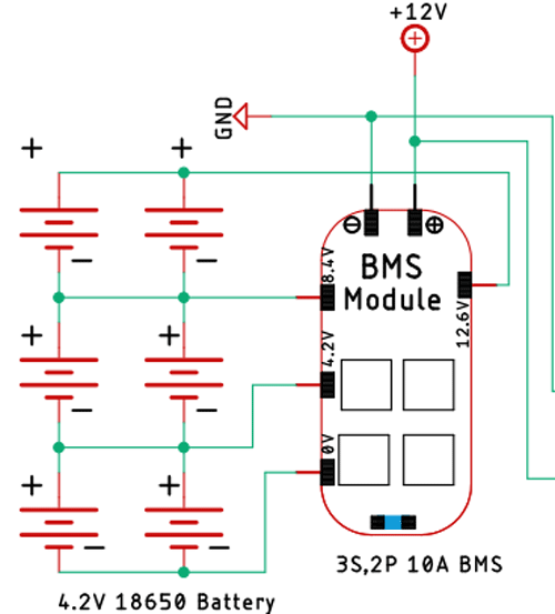
As we are using lithium batteries to power the circuit we need to take care of the charging and discharging process of the batteries otherwise its life expectancy will reduce drastically, which is why we are using a 10A 3s, 2P BMS module. This BMS module will ensure that the battery gets charged properly and it doesn't get over-discharged other than that this BMS module also protects the battery from short circuit and overload conditions. A closeup of the BMS circuit is shown below.
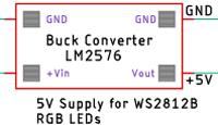
Next, we have the buck converter module. The buck converter module reduces the 12V coming from the battery and converts it to +5V so that we can power the Neo Pixel LEDs, Bluetooth Audio Receiver Module, and the ESP12E module.
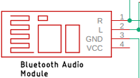
Next on the list is the Bluetooth audio receiver module itself. As the name implies this model is a Bluetooth audio receiver and we are connecting the output of the Bluetooth audio receiver to the input of the audio amplifier module.
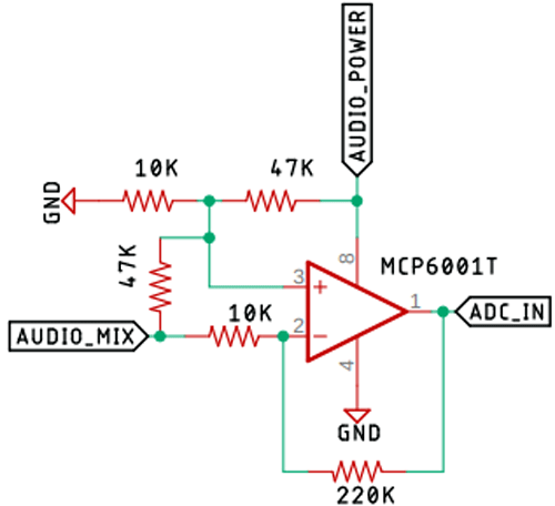
The output of the Bluetooth Audio Receiver module gets mixed with two 10K resistors and it gets directly to an MCP6001T low voltage op-amp whose job is to amplify the signal and to offset the audio source. Because without the offset only one part of the sine wave will get amplified and it would in return produce unwanted output. As the op-amp is a very low-power one we are using a GPIO pin of the ESP to power it, doing so we can turn on or off the LEDs at any time we want. This feature can come in very handy in low light conditions or in a dark room.
Now we have our ESP8266 module. To power the module we are using a AMS117 3.3V regulator, other than that in the module we have connected some WS2812 Neo Pixel LEDs. The data pin for the Neo Pixels is the RX pin of the ESP module and it cannot be changed as the code uses I2S of the ESP module to drive the LED and for the input side, we are using the A0 pin of the ESP which is connected to the output pin of the op-amp. Finally as mentioned before, we are using the gpio14 of the module to power on/off the op-amp.
![]()
Once the schematic was done, I started to build the ESP circuit on a piece of perfboard as I was in a hurry to build this project. I soldered the components very rationally and it's absolutely not recommended, an image of the circuit board is shown below.

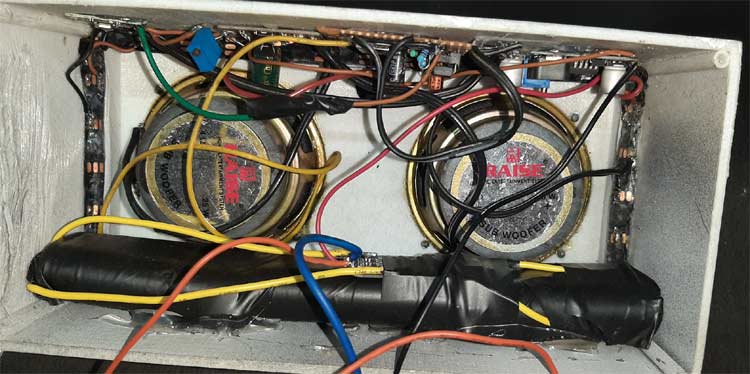
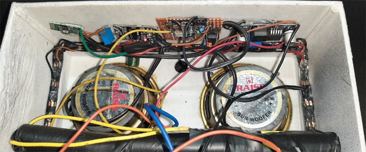
After that I started super gluing the 3D printed LEDs and finally, I have used some hot glue to secure the battery and the modules in place. The final build resembles the image shown below.
Once this was done, I soldered wires for a switch and a charging port and the build process was finished.
Note: If you are building the circuit yourself, please note that any version of node MCU boards will not work for this project. You have to use a bare bone ESP8266-12E module because as output we are using the RX pin and it cannot be changed because the colorchord uses I2S operations internally. Also, the ADC pin on a node MCU board goes to a voltage divider, which can also ruin your final result.
3D Designing and Printing the Parts of the Bluetooth Speaker
The enclosure for the Bluetooth speaker is completely made out of 3D printing part. To do so we first need to design the enclosure infusion 360. We started out by marking out the outside of the enclosure and made 3” circles inside. Then we offset the outer circle by 3mm to make a body so that we could extrude. Once that is done, we have repeated this process twice so that we could make a channel where the LEDs will fit.
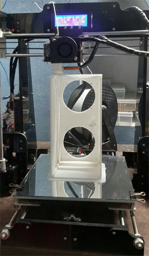
I exported it as an STL file, sliced it based on printer settings, and finally printed it. The STL file is also available for download from Thingiverse and you can print your enclosure using it.
Building our Bluetooth Speaker using Arduino, Neopixel and Enclosure
Once the 3D printing process was finished, I measured out the strip of Neo Pixels and cut them accordingly. After that, I used lots of super glue to stick the neo pixel LEDs in place according to Din and Dout markings and solder the VCC, GND, Din, and Dout pins with standard wires. Once that was done, I used a lot of hot glue to stick the battery in the bottom of the Bluetooth speaker. And solder wires that I used for charging the device. Once that was finished, I started soldering the Bluetooth module with other modules according to the schematic.
![]()
Compiling Colourcord on a Linux based System and Flashing it to an ESP82266
Now we have come to the most interesting and most important part of the build, without this step your Bluetooth speaker will work fine but your WS2812B LEDs will not light up at all, so follow the steps accordingly. Please note that in order for this process to work you must have a distribution of Linux installed in your system or you have to install and set up a window subsystem for Linux version 1 or WSL1, but that's way beyond the scope of this project. Now let's begin the compilation process for colourchord embedded.
If you are building this project for the first time, you need to go to the cnlohr esp82xx GitHub repo and follow the instructions.
Like any other Linux system, you need to update and upgrade your system and install some prerequisite.
sudo apt-get update && upgrade
sudo apt-get install -y make gcc g++ gperf install-info gawk libexpat-dev python2-dev
python2 python2-serial sed git unzip bash wget bzip2 libtool-bin
Now, if your system doesn't have python2 or pyserial you need to follow the instruction given below.
curl  https://github.com/pypa/get-pip/raw/5f38681f7f5872e4032860b54e9cc11cf0374932/get-pip.py --output get-pip.py
sudo python2 get-pip.py
pip install pyserial
Next, you need to pull the esp-open-sdk and extract it that will place the content of the archive in the home folder, and that is the default location of this SDK. Most of the ESP projects know to look there for the headers and other content.
mkdir -p ~/esp8266
cd ~/esp8266
wget https://github.com/cnlohr/esp82xx_bin_toolchain/raw/master/esp-open-sdk-x86_64-20200810.tar.xz
tar xJvf esp-open-sdk-x86_64-20200810.tar.xz
So, in the above step, we make a folder cd into it and we get the esp-open-sdk files and extract it.
Next, we have to install the NON-OS SDK from espressif and for that just copy-paste the commands below and hit enter.
cd ~/esp8266
git clone https://github.com/espressif/ESP8266_NONOS_SDK --recurse-submodules
Next, you need to make sure that you are part of the dialout group so that you could just go in and flash the file without root privileges, the command to do so is given below.
sudo usermod -aG dialoutdas
Once this is done you need to log out and log in, in order for the process to take effect.
Next, you need to add the location of the esp-open-sdk to bashrc with the command below.
export ESP_ROOT=/path/to/sdk/where/esp-open-sdk
We are done with setting up all the tools that are necessary to compile colorchord.
Now we need to get a copy of colorchord embedded from GitHub, and for that follow the instruction below. This will download the source code for colorchord and all of its dependencies.
git clone https://github.com/cnlohr/colorchord.git --recurse-submodules
Next, you need to cd into the embedded directory so that we can compile the version of colorchord for the esp8266.
cd colorchord/embedded8266
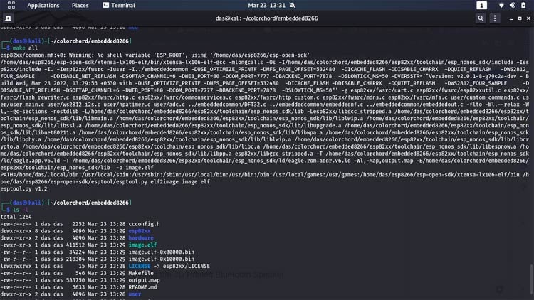
Now, all we have to do is just type make all, and hit enter.
If you have done everything correctly at this point you will get two bin files ready to be uploaded to esp8266. Now you have to flash the compiled bin files to ESP8266, if you are doing this for the first time you need to erase the memory of esp8266 completely, and additionally, it will flash some base files into the memory of the ESP module, to do so run the following commands. In place of <port value>, you need to add your USB port address. For me it was /dev/ttyUSB0.
PORT=<port value> make erase
PORT=<port value> make burnitall
If you have made any changes to colorchord and you want to test them use the command given below.
PORT=<port_value> make burn
If the flashing process went correctly, the ESP module should be broadcasting a Wi-Fi access point that you can connect to. Now if you connect to that access point go to 192.168.4.1 you will be presented with something that is shown below. It's the colorchord control panel where you can turn on or off a GPIO. You can select different DFT methods for different light effects, or you can change wi-fi settings, and do more.

*click on the GIF for a large view
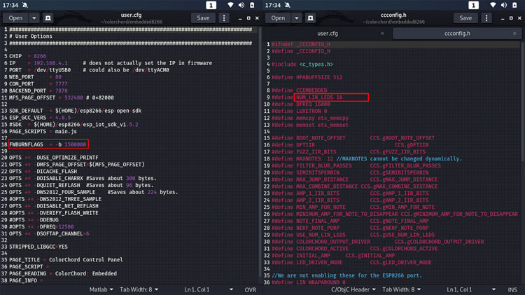
In the source code of colorchord there are two additional files you need to be aware of, first one is the user.cfg file and the second one is the ccconfig.h file. By default, you can only light up 16 LEDs if you need more LEDs than that you need to edit the ccconfig.h file and change the NUM_LIN_LEDS to your liking. Next is the user.cfg file, if you are having trouble with flashing the ESP you need to change the baud rate in the FWBURNFLAGS = -b 115200 baud or something else.
Testing the 3D Printed Bluetooth Speaker
While building the speakers I did not take that many pictures of the testing process because I was testing each and every module. First I tested the BMS module to see if it is working fine or not, for that I shorted the two output terminals and checked if the overcurrent protection was working or not, then I powered the LM2576 Buck Converter and set its output to 5V and then I soldered the Bluetooth module and the audio amplifier module according to the schematic and tested it. Finally, I separately built the esp8266 and op-amp circuit and connected some NeoPixel LEDs to test if they were working or not. And they were working exactly as expected.
With this, we are concluding our project on light-reactive Bluetooth speaker with colourchord. Hope you have enjoyed reading this and learned something useful. Now it’s time for you to build it on your own and let us know what you are doing with this project in the comment section below. If you have any questions or problems feel free to post them on our forums and we will get back to you.
