
By Vikas Singh Thakur
Introduction
In today's fast-paced world, managing home security, daily routines, and connectivity can be challenging, especially for busy individuals, elderly users, or those living alone. DIGI-HOME is a compact Home companion built on the Adafruit Memento board (powered by ESP32-S3), designed to make homes smarter, safer, and more interactive. By combining vision, IoT integration, and automation, it provides real-time monitoring, reminders, and controls accessible via its own APP, turning everyday tasks into seamless experiences.
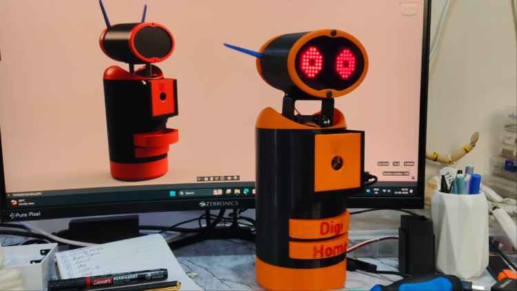
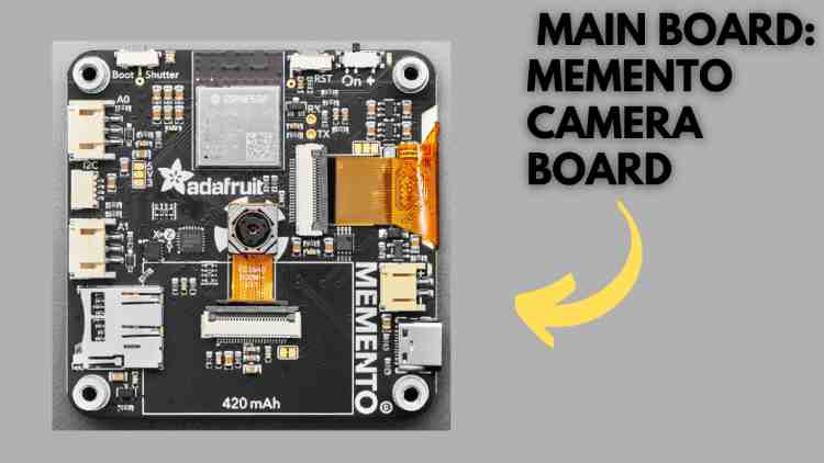
Completely Build Around Memento Camera Board By Adafruit (ESP-32 S3) which is sponsored By Digi-Key.
Problem Statement:
Modern homes often lack integrated systems for security, health reminders, and automation, leading to issues like forgotten tasks or activity reminders like meetings, reminder notes like medications, undetected intrusions, or inefficient device control. Traditional smart home devices are expensive, complex to set up, and lacks personalization.
For users in regions like India, where affordability and simplicity are key, there's a need for a low-cost, customizable solution that uses open-source hardware to handle motion detection, voice alerts, and physical interactions and event trigger (e.g., dispensing items) without relying on complex and heavy services.
Solution
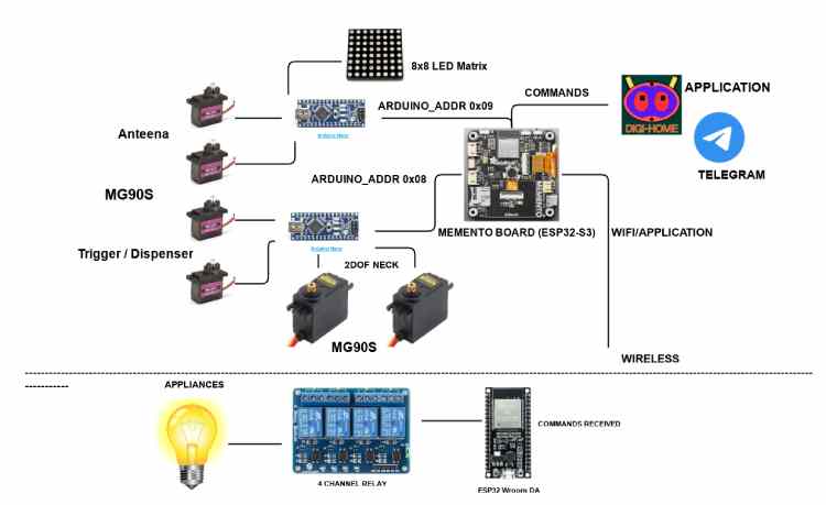
DIGI-HOME addresses these challenges with a Memento-based system that leverages its built-in camera for vision tasks, WiFi for Application and Telegram (Optional) connectivity, and I2C for interfacing multiple microcontrollers for more flexibility and feature addons. The device detects motion, tracks objects, schedules reminders, and automates actions like triggering some events based on scheduling like dispensing keys, reminder notes or dispensing medicine. All features are controlled via its simple application or for more flexibility through Telegram commands, ensuring ease of use. The open-source code allows customization, making it an affordable, DIY-friendly smart home hub.
Features
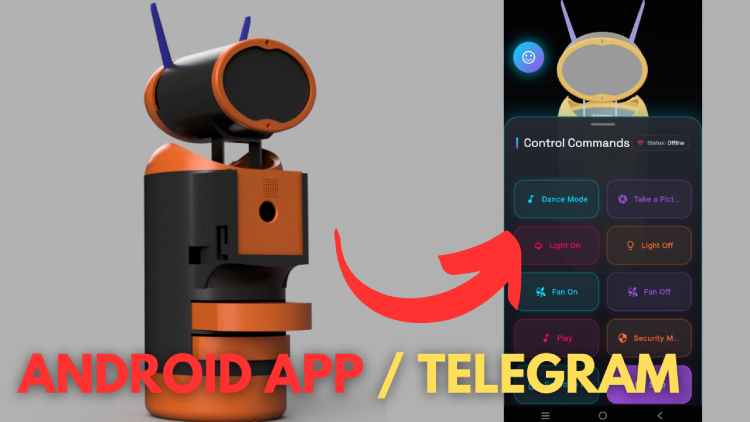
The Digi-Home robot offers a range of practical features designed to enhance home management, security, and daily convenience. These are accessible through a dedicated mobile application (Digi-Home) or Telegram integration, allowing real-time control from anywhere in the world without additional subscriptions or fees.
1. Dedicated Application and Telegram Control
The robot comes with its own app for managing all tasks, complemented by Telegram support. This setup enables seamless remote control, eliminating the need for multiple apps or recurring payments.
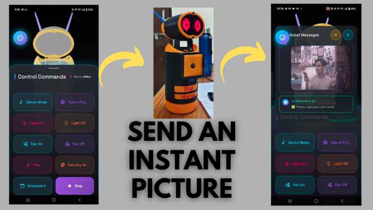
2. Snap Mode
When you're away from home and need to check on things, use the Digi-Home app to send a command from anywhere. The robot captures a current snapshot and sends it directly to your phone. All images are stored locally on an SD card for later retrieval, providing a simple way to stay informed.
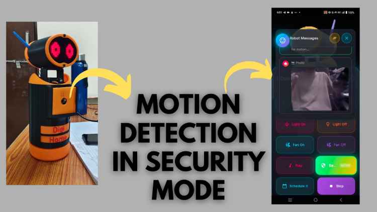
3. Security Mode
In this mode, the robot enters a continuous monitoring loop to detect any motion or movement in its environment while you're out. Upon detection, it captures a photo of the moment and sends an alert to your phone for verification. This helps keep your home and loved ones secure. Data is also saved to the local SD card, ensuring access even if the internet connection is interrupted.
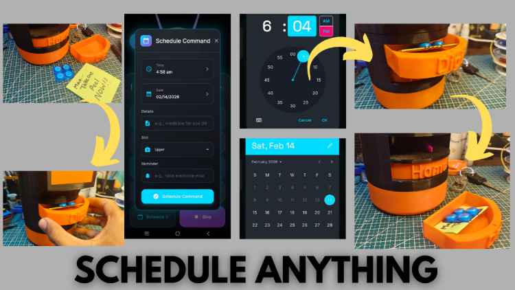
4. Schedule Mode
In a busy lifestyle, it's easy to forget important tasks like meetings, appointments, or taking medication. With Schedule Mode, you can set reminders for any date and time via the Digi-Home app from anywhere. Add custom notes, such as reminders for medicine or keys, and the robot will notify you precisely on time. Reminders are stored in memory, so they're preserved even if the robot is powered off and will trigger when it's turned back on.
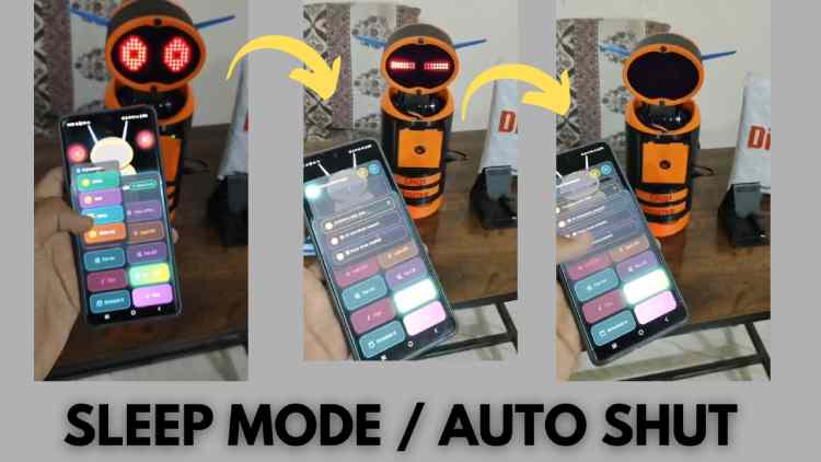
5. Sleep Mode
To conserve power, select Sleep Mode from the app's expressions menu. This shuts down the robot efficiently, extending its operational time when not in use.
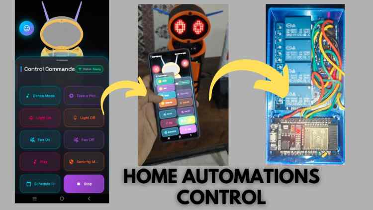
6. Home Automation Integration
Connect the robot to wireless smart devices by entering their IP addresses in the configuration. This allows control of commands like turning lights on or off through the single Digi-Home platform, centralizing home automation without needing separate apps.
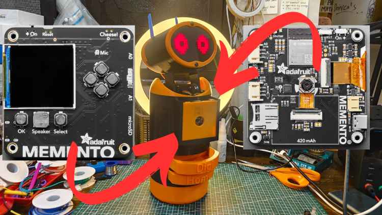
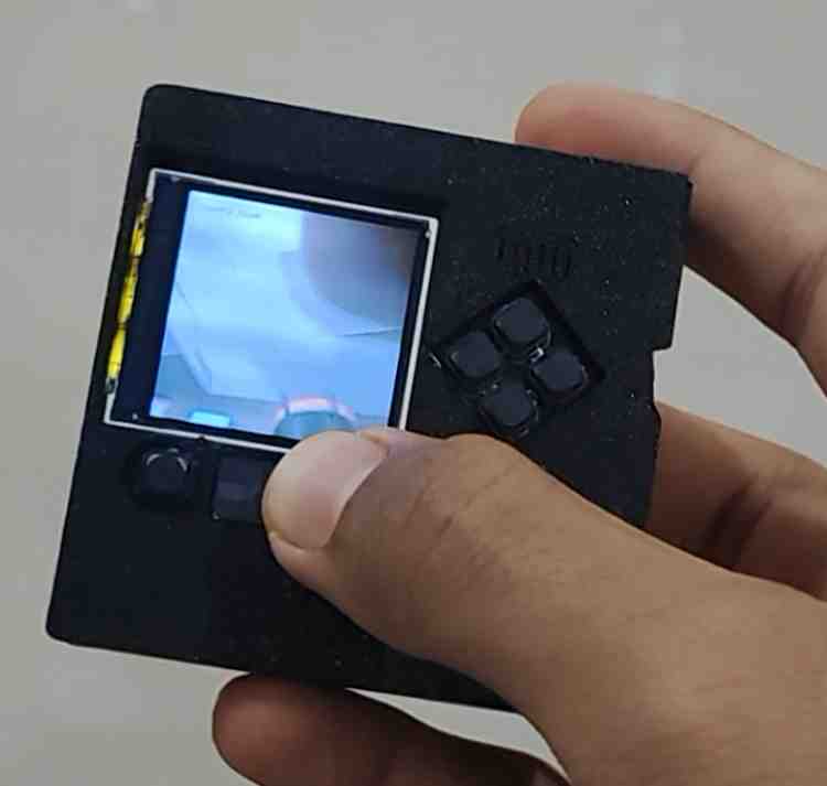
7. Easily Swappable Module (PyCamera)
The robot's board is designed with minimal connections for easy removal, allowing it to function independently. It includes a built-in TFT screen and high-resolution camera, enabling additional uses. Navigate options via the board's buttons, including:
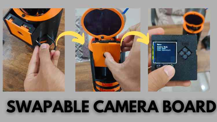
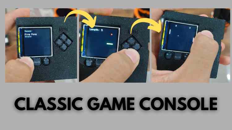
- Games: Play classic games like Ping Pong or Snake for light entertainment.
- Camera Option: Use the board as a portable camera for taking photos outdoors. Powered by its own lithium-ion battery, it's handy for loved ones in emergencies—capturing and automatically sending images to designated contacts for added safety and connectivity.
- Assistant Mode: Return the board to the robot's main body to resume standard operations.
8. Expressible Features and Movements
The robot's natural movements and facial expressions, such as eye motions, make it feel more engaging and responsive, similar to a pet that reacts locally without relying on external servers.
9. Interactable Mode
Customize expressions or activate entertainment options like dancing and expression changes for casual interaction and fun.
IF YOU WANNA BUILD ONE, THEN I HAVE MADE ALL THE HARD PARTS, ALL YOU NEED TO DO IS FOLLOW THE STEPS:
I AM VIKAS
I LOVE ROBOTICS
ALL THE BEST FOR THE BUILD....
Components Required
| Component Name | Quantity | Datasheet/Link |
| Memento Board By Adafruit | 1 | View Datasheet |
| LM2596S DC-DC Buck Converter Power Supply (12v to 5 v) | 1 | View Datasheet |
| LED 8X8 Matrix | 2 | View Datasheet |
| MG995 Servo Motor (for Neck) | 2 | View Datasheet |
| MG90S Servo Motor (for Antenna & Dispensor) | 4 | View Datasheet |
| Arduino nano (to expand Pins) | 2 | View Datasheet |
| 24 Awg Wires bundle 5 meter | 1 | View Datasheet |
| eSun PLA+ 1.75mm (Color depends on your Choice) | 1 | View Datasheet |
| Soldering Iron (Recommended all Tools Are included in this)) | 1 | View Datasheet |
| Glue Gun | 1 | View Datasheet |
| ESP32 Wroom DA | 1 | View Datasheet |
| 4 Channel Relay (5v) | 1 | View Datasheet |
| li-ion Battery Pack (12v) Recommended | 1 | View Datasheet |
| Wall Adapter (5V 4amp) | 1 | View Datasheet |
| Screw Driver Set | 1 | View Datasheet |
| Wire Cutter | 1 | View Datasheet |
| DT830D Multimeter | 1 | View Datasheet |
| M4x8mm Screws | 8 | View Datasheet |
| 20x20cm 3mm thick acrylic sheet | 1 | View Datasheet |
Simple Flow Chart(Work Flow Of The Circuit):
Circuit Diagram (Main Body):
Note: Please refer to the PDF attached below for a clear, detailed view/Connections of the circuit.
Note: Please Use Color Coded Wires (Each Unique) to trace connections for a clear, detailed view/Connections in the circuit.


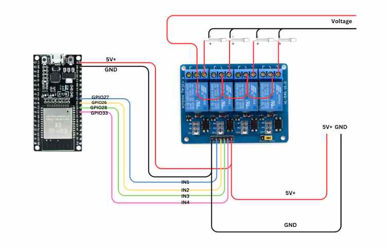
(Optional) Circuit Diagram For Wireless Appliances Control (For Trigger On/Off Control):
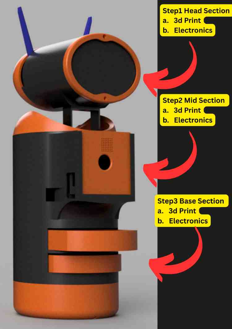
4. Hardware Assembly
This section provides a comprehensive guide to constructing the physical body of the DIGI-HOME and integrating the 3D printing Parts, electronics subsystems with (Memento Camera Board by Adafruit ).
Note: Please follow these exact steps to make the assembly part easy.
Note: For the 3D-CAD Models for 3d Printing, Please refere to my Github reposetory here:
https://github.com/vikas-meu/digi-home-hw.git
Precaution: Some heating elements and mechanical parts are used here so be very attentive while operating those.
4.1 Pre-Assembly Preparation
Before starting, ensure you have a clean workspace. This build involves higher voltage AC tools and voltage regulation, so safety is paramount.
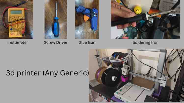
4.1.1 Tools & Components Required
- 3D Printer (PLA Filament recommended)
- Soldering Iron & Solder Wire
- Wire Strippers & Cutters
- Screwdriver Set (Phillips head)
- Hot Glue Gun
- Multimeter (Crucial for checking Buck Converter voltage)
- 3D printing Filament PLA (Color i optional here)
- An 20 cm x 20cm light pass acrylic plate (for the eys pass window)
- A grinding tool (For Cutting the acrylic)
Note: while doing this use a mask as the particals from the cut couse cause breating issues.
Key Components (from Circuit Diagram):
Main Board: Adafruit Memento (ESP32-S3)
- Sub-Controllers: 2x Arduino Nano (these are the cheapest alternatives)
- Actuators:
- 2x MG995 Servo Motors (High Torque for Neck/Base)
- 4x MG90S Servo Motors (For Dispenser/Antennas)
- Power: 12V Li-Ion Battery Pack + Buck Converter (Step-down module)
- Eyes: 8x8 Led Matrix Display
- 24awg wires with minimun 10meter length is prefered for good connection, but jumpers could also work here.

To build it correctly with fewer problems, follow these steps here:
STEP 1: Head Section
a. 3d printing each part with files named from a.stl-g.stl , please refer to the obj file for detailed structure view in my github.and after this cut the acrylic part using the grinder tool and use mask and you can do that by first 3d print teh a.stl then make an layout on paper tehn stick that o the scrylic sheet and following that layout cut the acrylic slowly.
b. after 3d printing all the files for head move to the the electronics part here you need, arduino nano, jumpers(wires),
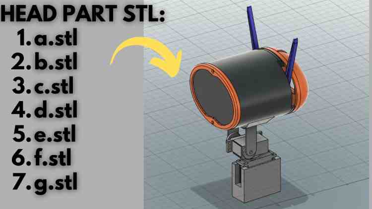
3D Printing the Head Parts
To manufacture the robot head, you need to 3D print the head components available in the official GitHub repository.
Download Link
Navigate directly to the 3D files section:
https://github.com/vikas-meu/digi-home-hw/tree/main/3d_files
Locating the STL Files
Inside the repository:
- Go to the 3d_files folder.
- Look for the .stl files named with simple abbreviations:
a.stl
b.stl
c.stl
d.stl
e.stl
f.stl
g.stl
Important Instructions
- Download all STL files into a dedicated folder on your system.
- Example folder name:
Digi_Home_Head_3D_Files
- Keeping them in one organized folder prevents confusion during slicing and printing.
Head Part File Names
File NameDescription (To Be Assigned During Assembly)a.stlHead Part Ab.stlHead Part Bc.stlHead Part Cd.stlHead Part De.stlHead Part Ef.stlHead Part Fg.stlHead Part G (You may rename them later based on their assembly position if needed.)
Next Step (Preparation for Printing)
After downloading:
- Open your slicing software (e.g., Cura / PrusaSlicer).
- Import each STL file.
- Arrange parts properly on the print bed.
- Apply suitable infill (recommended: 15–20% for structural parts).
- Slice and generate G-code.
Once printed: Assemble them by Following the images below:
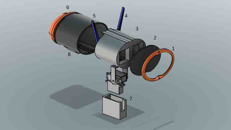
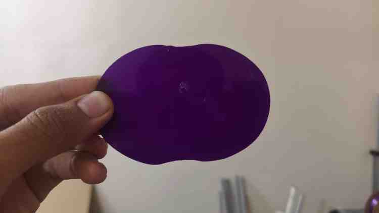
Note : Here to be noted that the part 2 is not a 3d printed part that is acrylic sheet: follow these steps to make your own:
Get a 20x 20 acrylic sheet and use part 1 to use as stelcile and make the pattern wing a pen or pencile on a paper and stick that paper on top of the acrylic sheet and using the a metal cutter or using grinding tool (Recommended) cut that peice out.
(Precaution: Use Mask)
The final Output should look like this:
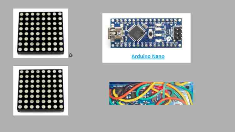
Electronics Part:
Here you will be needing:
arduino nano, a zero pcb board, jumpers, 8x8 lead matrix , 2x mg90s servo motors, 2x mg995 servo motor, Glue Gun:
Follow the Circuit diagram from the previous section and follow the exact pins, and assemble every part carefully:
Then upload the code named: Arduino_head_0x09.ino: https://github.com/vikas-meu/digi-home-hw/blob/main/head_arduino_0x09.ino
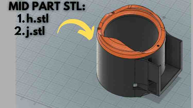
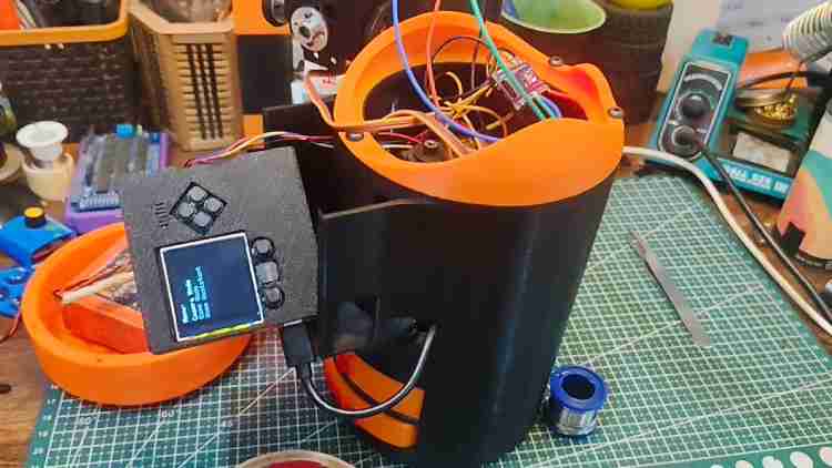
Step 2: Mid Section
3D Printing the Mid-Section Parts
The mid-section forms the central structural body of the robot and houses internal components including the Memento board.
All required files are available in your GitHub repository.
Download Link
Navigate to the mid-section folder directly:
https://github.com/vikas-meu/digi-home-hw/tree/main/3d_files/part2_mid_section
Required STL Files
Inside this folder, download the following files:
h.stl
i.stl
These parts together form the mid-structural frame of the Digi Home robot.
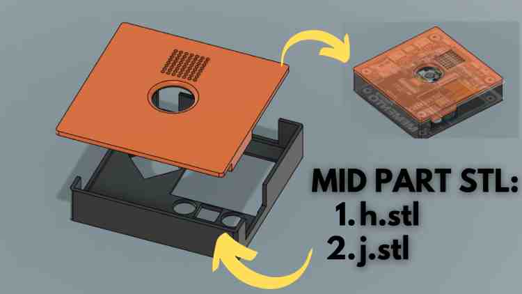
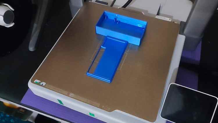
Memento Board Cover
In the same folder (part2_mid_section), you will also find the dedicated protective enclosure for the Memento board.
Download and 3D print:
memento_cover_lower.stl
memento_cover_upper.stl
These two parts assemble together to create the complete protective case for the Memento board.
Important Instructions
Create a separate folder on your system for better organization:
Digi_Home_Mid_SectionKeep the following files together:
h.stl
i.stl
memento_cover_lower.stl
memento_cover_upper.stlThis prevents confusion during slicing and assembly.
Printing Recommendations
- Infill: 20% (recommended)
- Material: PLA (recommended for easy printing)
Supports:
- Required for overhang sections
- Especially for cover parts depending on orientation
- Layer height: 0.2 mm for balanced quality
Assembly Note
- The mid-section frame (h.stl & i.stl) supports the head assembly above and electronics inside.
- The Memento cover protects the ESP32 camera board and should be assembled using small screws after wiring is completed.
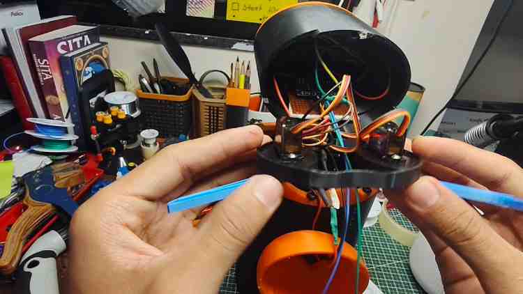
Electronics For Mid Section
Required Components
For assembling the electronics in the mid-section, you will need the following:
- Arduino Nano
- Soldering iron
- Solder wire
- Glue gun (for mechanical fixing)
- Jumper wires (Male–Male / Male–Female as required)
- Servo motors (as per design)
- I2C connection wires (SDA, SCL)
Reference Code
The wiring and logic must follow the Arduino firmware provided in your GitHub repository.
Direct link to the code: https://github.com/vikas-meu/digi-home-hw/blob/main/head_arduino_0x08.ino
Purpose of This Arduino (Mid Section Controller)
This Arduino (I2C Address 0x08) controls:
- Neck Roll Servo
- Neck Yaw Servo
- Medicine Dispenser Servo 1
- Medicine Dispenser Servo 2
- Motion Modes (Normal / Dance / Security)
- Sleep / Wake states
And Finally The last part:
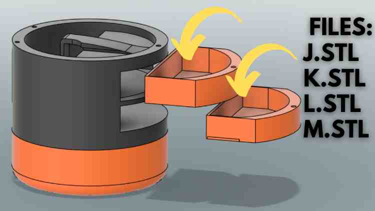
STEP 3: Base Section (Part 3)
3D Printing the Base Parts
This is the final structural section of the Digi Home Robot.
These parts form:
- Medicine dispenser slot housing
- Battery holder base
- Bottom structural support
Download Link
Navigate to your GitHub 3D files section: https://github.com/vikas-meu/digi-home-hw/tree/main/3d_files
Locate and download the following STL files:
j.stl
k.stl
l.stl
m.stl
Organize Files Properly
Create a dedicated folder on your system:
Digi_Home_Base_Section
Place these files inside:
j.stl
k.stl
l.stl
m.stl
Proper organization avoids confusion during slicing and assembly.
Printing Recommendations
- Material: PLA (recommended)
- Infill: 25(stronger support for battery weight)
- Layer Height: 0.2 mm
- Supports: Enable for overhang areas if required
- Wall Thickness: 1.2 mm minimum (for durability)
Assembly Notes
- Install dispenser servo mechanisms into the designated slot section.
- Secure battery holder firmly to prevent movement.
- Ensure wiring passage holes remain accessible.
- Use screws where possible instead of glue for maintenance access.
Final Electronics & Power System Installation
This is the last step of the Digi Home Robot assembly.
In this step, you will:
- Install the battery
- Connect a buck converter
- Add a power switch
- Perform proper soldering
- Finalize power distribution
Required Components
- Rechargeable Battery (e.g., 7.4V Li-ion / 11.1V Li-ion depending on your design)
- Buck Converter (DC-DC Step Down Module)
- ON/OFF Toggle or Rocker Switch
- Soldering Iron
- Solder Wire
- Heat Shrink Tubes
- Multimeter (VERY IMPORTANT for testing)
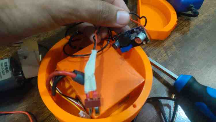
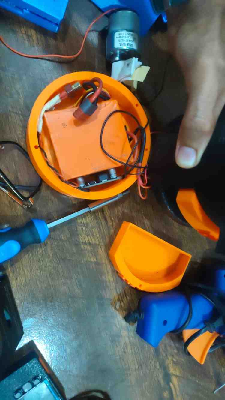
Battery Installation
Mounting
- Place the battery inside the base section battery holder (l.stl).
- Secure it using:
- Double-sided tape
- Velcro strap
- Or battery clamp system
- ⚠ Make sure the battery does not move during robot operation.
Buck Converter Connection
The buck converter is used to:
- Step down battery voltage
- Provide stable 5V output
- Protect electronics
Connection Flow
Battery → Switch → Buck Converter → Electronics
Wiring Steps
Step 1: Connect Battery to Switch
- Battery Positive (+) → Switch Input
- Switch Output → Buck Converter VIN+
- Battery Negative (–) → Buck Converter VIN–
This ensures the switch cuts the entire system power.
Step 2: Set Buck Converter Output
Before connecting electronics:
- Power ON
- Use multimeter
- Adjust potentiometer
- Set output to:
- 5.0V exactly
⚠ DO NOT connect electronics before voltage adjustment.
Step 3: Connect Output to System
Buck Converter OUT+ →
- Arduino Nano 5V
- ESP32 5V input
- Servo power line
Buck Converter OUT– →
- Common GND
- Arduino GND
- ESP32 GND
- Servo GND
All grounds must be common.
Installing the Power Switch
Mount the switch in the base section:
- Drill slot in base part if needed
- Secure switch firmly
- Ensure easy access from outside
Switch must be placed in the battery positive line only.
Final Power Testing Checklist
Before closing the base:
Electrical Tests
- Output voltage = 5.0V
- No short circuit
- Switch cuts full power
- Buck converter not overheating
Important Safety Notes
- Never short Li-ion battery terminals
- Never charge battery without proper charger
- Never exceed servo current rating
- Use fuse (optional but recommended)
FINAL STEP: PROGRAMMING ALL CONTROLLERS
This is the final configuration step.
You will program:
- Head Arduino Nano (0x09)
- Base Arduino Nano (0x08)
- Memento ESP32 (PyCamera Board)
Program the Head Arduino (Eyes & Expressions – 0x09)
File to Upload
head_code_0x09.ino
(From my GitHub repository)
Connection Steps
- Connect Arduino Nano to computer using USB Type-C / Mini-USB (depending on your Nano version).
- Open Arduino IDE.
- Select:
Tools → Board → Arduino Nano
Tools → Processor → ATmega328P (Old Bootloader if required)
Tools → Port → Select correct COM port
Upload the Code
- Open head_code_0x09.ino
- Click Upload
Wait until you see:
Done uploading.
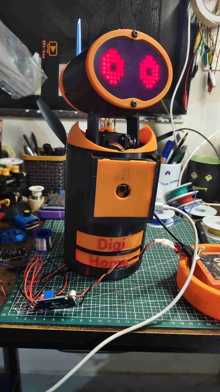
Expected Result
After uploading:
- LED matrix eyes should light up
- Default blinking animation should start
- Eye servos should begin random movement
If working correctly → Head section is programmed successfully.
Program the Base / Neck Arduino (0x08)
File to Upload
base-0x08.ino
(From GitHub repository)
Connection Steps
- Disconnect head Nano.
- Connect base Arduino Nano via USB.
- Keep same board settings in Arduino IDE.
- Select correct COM port.
Upload the Code
Open base-0x08.ino
Click Upload
Expected Result
After successful upload:
- Neck servo starts smooth random movement
- If in NORMAL mode → Idle motion visible
- Dispenser servos remain in resting position
- Movement should match your demonstration video
If servo motors start moving → Base controller is working properly.
Program the Memento ESP32 (Main Controller)
File to Upload
pycamera.ino
Enter Firmware Upload Mode
- Connect Memento board using USB Type-C.
- Press the RESET button twice quickly.
- The board will enter Firmware Mode.
You should see a new COM port appear.
Arduino IDE Settings for ESP32
- Tools → Board → ESP32 Dev Module
- Tools → Port → Select new COM port
- Upload Speed → 921600 (recommended)
IMPORTANT: Add Telegram Credentials
Before uploading, edit:
const char* ssid = "YOUR_WIFI_NAME";
const char* password = "YOUR_WIFI_PASSWORD";
#define BOTtoken "YOUR_TELEGRAM_BOT_TOKEN"
#define CHAT_ID "YOUR_CHAT_ID"⚠ Without correct credentials, Telegram features will not work.
Upload pycamera.ino
Click Upload.
If upload fails:
Hold BOOT button while uploading.
Wait for:
Hard resetting via RTS pin...
Expected Result After Upload
- Camera display turns ON
- Device connects to WiFi
- Telegram bot becomes active
- Motion detection ready
- I2C communication starts with both Arduinos
Test via Telegram:
/pic
You should receive a photo.
Final System Test Checklist
- Head eyes blinking
- Neck moving
- Dispenser responding
- Telegram commands working
- Security mode functioning
- Fan/light control working
Full System Programmed Successfully
You have now:
Printed all mechanical parts
Installed electronics
Installed power system
Programmed all controllers
Your Digi Home Robot is now fully operational.
If you want, I can now create:
- Complete Final Assembly & Programming Manual (Combined Clean Version)
- System Architecture Diagram
- Wiring Diagram Illustration
- Final Year Project Report Format
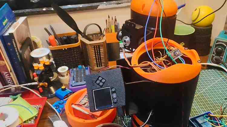
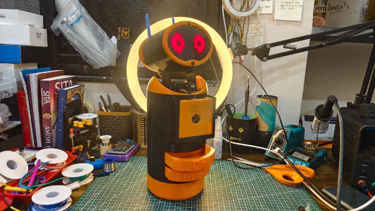
Assemeble everything and you get your digi-home in your desk
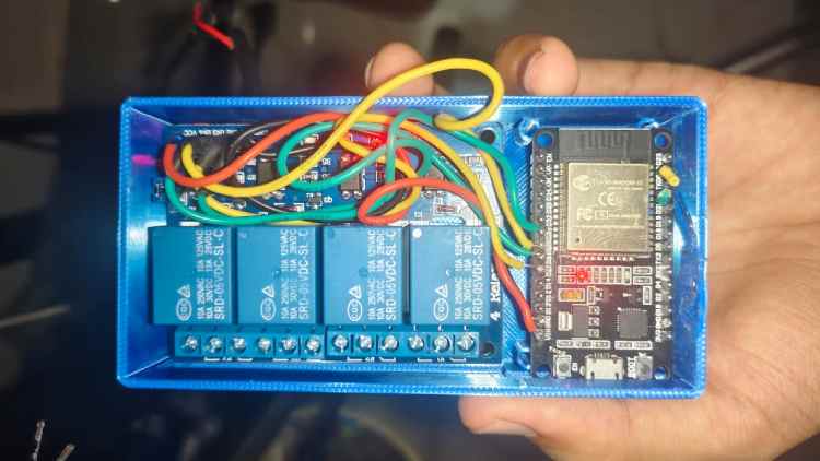
Optional Part for teh home automations:
you can builld this extras esp32 based relay based controller and use the circuit in the circuit section and use teh code from the github and files for this is available in the optional_mode folder section in my github just 3d print it and attach all the relay boards and aesp32 with the applience adn configure the wifi credentials
when you get the ip addres from th serila monitor jus tcopy paste that in the memento camera board
Code Explanation
Digi-Home Hardware Code Documentation
For all code inside vikas-meu/digi-home-hw (GitHub)
Repository Structure
/3d_files/ ← 3D models for robot parts
/Slave_Boards/ ← Arduino controllers
/src/pycamera/ ← Main ESP32 firmware code
Base_trigger.ino ← Base Arduino logic
esp32_relay_module.ino ← ESP32 web & IoT module
head_arduino_0x09.ino ← Head Arduino code
esp32_relay_module.ino ← Relay control for appliances
README.md ← Overview and setup instructions
LICENSE ← GPL-3.0 License
(GitHub)
1. Base Controller — Base_trigger.ino
Purpose
Controls the neck movement, idle animations, and medicine dispensers via an Arduino Nano at I2C address 0x08.
It acts as the motor controller and motion engine for the robot.(GitHub)
Key Functional Blocks
I2C Address
#define ARDUINO_ADDR 0x08Sets the Arduino as I2C Slave 0x08 on the common I2C bus.(GitHub)
Servo Configuration
Servos are attached to pins:
neckRoll.attach(3);
neckYaw.attach(5);
dispenser1.attach(6);
dispenser2.attach(9);
Controls: neck servos & two dispensers.(GitHub)
Modes
ModeBehaviorNORMALIdle head motionDANCEServo dance patternSECURITYSweep motionSLEEPStops movementAlive / Idle Motion
Smooth motion uses a lerp-style movement:
currentPos += (targetRoll - currentPos) * 0.10;
This creates smooth, natural transitions. (GitHub)
Dispensing Logic
The dispense() function moves a servo all the way to dispensing position and then back with delays for mechanical accuracy.(GitHub)
2. Head Arduino — head_arduino_0x09.ino
Purpose
Controls the animatronic face with LED matrix eyes and servo movements.
Head runs on second Arduino Nano at I2C address 0x09.(GitHub)
Main Functionalities
Eye Patterns
Predefined 8×8 bitmap arrays represent expressions:
- eye_open
- eye_sad
- eye_happy
- eye_closed
- eye_secure
The display updates columns quickly to animate expressions.(GitHub)
Blink Logic
Random timer triggers closed-eye frame for ~150 ms at random intervals, simulating blinking.(GitHub)
Servo Control
Left and right eye servos move smoothly using:
smoothMove(targetPos);
Creates natural head/eye movement.(GitHub)
Sleep & Secure Modes
Different states alter both LED patterns and servo behavior.(GitHub)
3. ESP32 IoT Module — esp32_relay_module.ino
Purpose
Provides local web control and REST API for high-voltage appliances (lights, fans, etc.).
Runs on an ESP32 and exposes URLs like:
/light_on
/fan_off
to toggle GPIO outputs.(GitHub)
Web Server Logic
HTTP Routes
Each endpoint toggles a specific relay or output pin.
server.on("/light_on", handleLightOn);
This allows control via browser or network requests.(GitHub)
4. I2C Communication — Shared Logic
Architecture
ESP32 (master)
│
├─ Nano #1 @ 0x08 → Neck & Dispenser
└─ Nano #2 @ 0x09 → Head & Expressions
All boards share common SDA / SCL lines on I2C bus.(GitHub)
⚠ Key Rules
✔ Common ground must be shared between all boards
✔ Pull-up resistors recommended for long I2C runs
✔ Each board has unique I2C address (0x08 & 0x09)(GitHub)
5. Helper Files & Misc
esp32_relay_module.ino
- Hosts simple IoT server
- Requires WiFi credentials before upload
- Serves control UI for lights/fan
- Maps REST endpoints to GPIO outputs(GitHub)
6. Libraries Used
LibraryPurpose
Servo.h : Creates PWM for servo motors
Wire.h : I2C communication
MD_MAX72XX : Drives 8×8 LED matrices
WiFi.h : ESP32 WiFi connectivity
WebServer.h : ESP32 web server support
UniversalTelegramBot.h / ArduinoJson : Telegram interface
NTPClient.h / WiFiUdp.h : Time syncing for scheduler
7. Deployment & Usage Flow
- Program Nano #1
Base_trigger.ino - Program Nano #2
head_arduino_0x09.ino - Program ESP32
esp32_relay_module.ino (plus WiFi creds) - Connect I2C
- Power and test servos & display
- Verify REST control via browser(GitHub)
8. Expected System Behavior
✔ Head eyes animate & blink
✔ Neck idle motion moves smoothly
✔ Servos respond to all modes
✔ Dispensers activate on commands
✔ Web UI toggles appliances (GitHub)
Troubleshooting
Servos twitch or reset
- Weak power supply
- Connect servos to dedicated 5V source
I2C data fails
- Missing GND
- Add pull-ups (≈ 4.7 kΩ)
ESP32 won’t connect to WiFi
- Ensure 2.4 GHz network and correct credentials
LED matrix displays garbage
- Try different MD_MAX72XX hardware type settings(GitHub)
Absolutely — here’s a clean, complete code documentation for the entire Digi-Home App repository on GitHub: https://github.com/vikas-meu/digi-home-app
Digi-Home App – Code Documentation
Repository Overview
/app/ ← Android Kotlin app code
/app/src/main/java/... ← Main source code
/app/src/main/res/... ← UI resources (layouts, drawables)
/app/src/main/AndroidManifest.xml
build.gradle ← Gradle config
README.md
The Digi-Home App is a mobile controller application designed to interface with the Digi-Home robot, enabling:
✔ Home automation control
✔ Teleoperation commands
✔ Video stream and telemetry
✔ App-based robot interaction
Application Structure
/app/
│
├── /src/
│ ├── /main/
│ │ ├── /java/com/vikas/digihome/
│ │ │ ├── Activities/
│ │ │ ├── Adapters/
│ │ │ ├── Helpers/
│ │ │ ├── Models/
│ │ │ └── ViewModels/
│ │ ├── /res/
│ │ │ ├── layout/
│ │ │ ├── drawable/
│ │ │ ├── values/
│ │ │ └── navigation/
│ │ └── AndroidManifest.xml
├── build.gradle
└── README.md
Main Components
ComponentPurposeActivitiesUI Screens and logicAdaptersRecycler adapters for listsHelpersUtility functionsModelsData structuresViewModelsMVVM logiclayoutsXML UI files 2. Core Modules
2.1 Activities
MainActivity.kt
Purpose:
- Launches the main UI
- Handles navigation
- Sets up listeners for buttons
Key Functions:
- onCreate()
- Inflates the layout
- Sets up navigation controller
- Initializes observers
ControlActivity.kt
Purpose:
- Primary control interface for robot actions
- Sends commands via HTTP or broadcasts
Key UI Elements:
- Buttons for:
- Light ON / OFF
- Fan ON / OFF
- Robot command toggles
Network Calls:
- Uses Retrofit / HttpUrlConnection
- Sends REST requests to the robot’s ESP32 relay endpoints
Example:
fun sendControlCommand(endpoint: String) {
   val url = "http://$controllerIP/$endpoint"
   // HTTP request logic
}
2.2 ViewModels
MainViewModel.kt
Purpose:
Holds UI data for activities and manages state.
Key responsibilities:
LiveData for network response
Data binding to UI
Handling asynchronous calls
2.3 Models
Typical classes include:
data class DeviceStatus(
   val name: String,
   val state: Boolean
)
Models represent:
- UI state
- Telemetry data
- Robot status
2.4 Helpers & Utils
Contains:
- Network helpers
- Shared preferences
- Logging utilities
- Input validation functions
Examples:
class NetworkHelper { ... }
class PreferenceManager { ... }
These promote DRY code and readability.
3. UI / Layouts
layout/activity_main.xml
- Host of navigation components
- Sets theme and toolbar
layout/activity_control.xml
UI Controls:
- Buttons for appliance control
- Toggle switches
- Data displays
navigation/nav_graph.xml
Defines navigation between screens:
- Home
- Controls
- Settings
- Camera view
4. Networking
Retrofit / HTTP Logic
The app sends simple GET requests to the robot ESP32 module to trigger actions.
Typical network call:
val url = "http://$controllerIP/$endpoint"
val request = Request.Builder().url(url).build()
// Execute
No heavy protocol — simple REST.
5. MVVM Architecture
ViewModels
Hold UI state in observable LiveData.
Example:
val statusLiveData: MutableLiveData<DeviceStatus> = MutableLiveData()Activities
Observe LiveData and update UI.
Models
Represent data cleanly with Kotlin data classes.
6. Permissions
In AndroidManifest.xml:
<uses-permission android:name="android.permission.INTERNET"/>
Required to send HTTP requests to the robot.
7. Control Logic
Light ON/OFF
Sends:
/light_on
/light_off
Fan ON/OFF
Sends:
/fan_on
/fan_off
Custom Commands
Handled similarly via REST.
8. Navigation & UI Flow
1. MainActivity
- Home screen
- Navigates to Control screen
1. ControlActivity
- Shows buttons
- Sends commands
1. Camera Screen
- May show robot camera (if supported)
9. Error Handling
The app includes basic:
- Toast alerts for errors
- Logging
- Retry mechanisms
Example:
Toast.makeText(context, "Failed to connect", LENGTH_SHORT).show()
10. Test Cases
✔ Verify HTTP Commands
Each button should fire the appropriate endpoint.
✔ Validate ViewModel updates
UI should react to LiveData changes.
✔ Check Navigation
Buttons should navigate smoothly.
11. Build Instructions
- Clone the repo
- Open in Android Studio
- Connect test device or emulator
- Build & Run
12. Troubleshooting
Network Errors
- Ensure robot and phone are on the same WiFi
- Incorrect IP → Endpoint failure
UI freezes
- Ensure network calls are done in background threads
Buttons not responsive
- Confirm activity is properly initialized
Summary
The Digi-Home App codebase demonstrates:
✔ Clean MVVM architecture
✔ Simple REST communication with robot
✔ Modular UI
✔ Network helpers
✔ Activity + ViewModel separation
✔ Expandable control features
What I can create next
Full App PDF documentation
Wireframe + navigation flowchart
User manual (APK UI guide)
A combined hardware + app project report
Just ask!
GitHub Repository


