
This ESP32 project is an exciting and interactive way to control LEDs using hand gestures. We will use an ESP32 board, Python, MediaPipe, and OpenCV to create a system that can detect specific hand gestures and translate them into actions that control LEDs. MediaPipe will be used to recognize the hand gestures, while OpenCV will capture the real-time video feed from a webcam. Based on the gestures (such as open hand, fist, or finger movements), commands will be sent to the ESP32, which will control the LEDs connected to it. This will allow us to turn LEDs on and off, change their brightness, or even control different LEDs with specific gestures. It’s a practical and fun way to learn about gesture recognition, hardware control, and communication between Python and microcontrollers.
Table of Contents
- Overview
- Components Required
- Circuit Diagram
- ESP32 Arduino Code to Control LEDs with Hand Gesture
- └ Libraries Used
- └ Complete ESP32 Code
- └ Code Explanation
- Python Code using OpenCV and Media Pipe
- └ Libraries Used
- └ Complete Python Code
- └ Python Code Explanation
- ESP32 Hand Gesture Project - Working Demo
- Similar Projects Using Gesture Control Systems
Overview
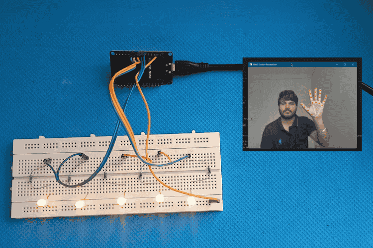
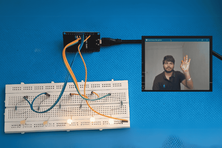
This project demonstrates how to control LEDs using hand gestures through a combination of Python, OpenCV, and the ESP32 microcontroller. Hand gestures are recognized via a webcam and processed with MediaPipe, a library designed for hand-tracking and gesture recognition. Each detected gesture is mapped to an LED control command, such as turning LEDs on or off. This allows for interactive control of the LEDs with simple hand movements.
The commands generated from hand gestures are sent wirelessly to the ESP32 over Wi-Fi using HTTP requests. Acting as a server, the ESP32 receives these commands and controls the LEDs connected to its GPIO pins. This project integrates computer vision, embedded systems, and networking, offering an excellent starting point for beginners interested in gesture-based control systems, IoT, and hardware-software integration.
Components Required
1. ESP32 Board - 1 ( ESP32 is used as the controller for handling commands sent based on the hand gestures recognized by the camera )
2. LEDs (5 pieces) for each finger (Thumb, Index, Middle, Ring, Pinky)
3. Resistors (Five 220 Ohms for each LEDs )
4. Jumper wires ( Male to Female )
5. Breadboard
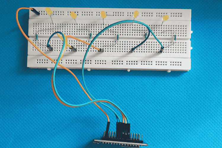
Circuit Diagram

To control 5 LEDs using an ESP32, the LEDs are connected to specific GPIO pins on the ESP32, with each LED corresponding to a unique hand gesture. The positive terminal (anode) of each LED is connected to a dedicated GPIO pin, such as GPIO pins 14, 27, 26, 25, and 33, which will control the LEDs. These GPIO pins provide the necessary voltage to turn on each LED. To prevent excess current from damaging the LEDs or the ESP32, a 220Ω or 330Ω resistor is connected in series with each LED. The resistors are crucial because they limit the current flowing through the LEDs, ensuring safe operation.
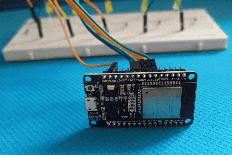
The negative terminal (cathode) of each LED is then connected to the ground (GND) of the ESP32. This establishes a complete electrical circuit for each LED. When a GPIO pin is set to HIGH, it sends a voltage to the anode of the LED, causing the LED to light up. Conversely, setting the GPIO pin to LOW turns the LED off. With the right connections, the hand gesture control system can effectively turn each LED on or off based on the detected gesture, making the setup interactive and useful for various applications.
ESP32 Arduino Code to Control LEDs with Hand Gesture
Now, let’s break down the code logic and functionality for this sound localization project.
This code sets up an ESP32 as a web server that controls 5 LEDs corresponding to the thumb, index, middle, ring, and pinky fingers. Each LED is connected to a specific GPIO pin and can be turned on or off via HTTP requests. The ESP32 connects to WiFi using the provided credentials, and once connected, it serves endpoints for controlling each LED. When a user accesses the URL corresponding to an LED (e.g., "/led/thumb/on"), the respective LED turns on and responds with a message. The server operates on port 80 and handles requests to control the LEDs.
Now let's break down the code, starting from the utilized library.
Libraries Used
ESPAsyncWebServer - Available in Library Manager
Wire - default library
Complete ESP32 Code
#include <WiFi.h>
#include <ESPAsyncWebServer.h>
const char* ssid = "Wifi_name";
const char* password = "Wifi_password";
AsyncWebServer server(80);
// Define GPIO pins for LEDs
const int thumbLedPin = 27;
const int indexLedPin = 26;
const int middleLedPin = 25;
const int ringLedPin = 33;
const int pinkyLedPin = 32;
void setup() {
 Serial.begin(115200);
 pinMode(thumbLedPin, OUTPUT);
 pinMode(indexLedPin, OUTPUT);
 pinMode(middleLedPin, OUTPUT);
 pinMode(ringLedPin, OUTPUT);
 pinMode(pinkyLedPin, OUTPUT);
 digitalWrite(thumbLedPin, LOW);
 digitalWrite(indexLedPin, LOW);
 digitalWrite(middleLedPin, LOW);
 digitalWrite(ringLedPin, LOW);
 digitalWrite(pinkyLedPin, LOW);
 Serial.println("Connecting to WiFi...");
 WiFi.begin(ssid, password);
 int attempts = 0;
 while (WiFi.status() != WL_CONNECTED && attempts < 20) {  // Try for 20 seconds
   delay(1000);
   Serial.print(".");
   attempts++;
 }
 if (WiFi.status() == WL_CONNECTED) {
   Serial.println("\nConnected to WiFi");
   Serial.print("IP Address: ");
   Serial.println(WiFi.localIP());
   // Define HTTP request handlers for each LED
   server.on("/led/thumb/on", HTTP_GET, [](AsyncWebServerRequest *request){
     digitalWrite(thumbLedPin, HIGH);
     request->send(200, "text/plain", "Price - 300");
   });
   server.on("/led/thumb/off", HTTP_GET, [](AsyncWebServerRequest *request){
     digitalWrite(thumbLedPin, LOW);
     request->send(200, "text/plain", "Thumb LED is OFF");
   });
   server.on("/led/index/on", HTTP_GET, [](AsyncWebServerRequest *request){
     digitalWrite(indexLedPin, HIGH);
     request->send(200, "text/plain", "Index finger LED is ON");
   });
   server.on("/led/index/off", HTTP_GET, [](AsyncWebServerRequest *request){
     digitalWrite(indexLedPin, LOW);
     request->send(200, "text/plain", "Index finger LED is OFF");
   });
   server.on("/led/middle/on", HTTP_GET, [](AsyncWebServerRequest *request){
     digitalWrite(middleLedPin, HIGH);
     request->send(200, "text/plain", "Middle finger LED is ON");
   });
   server.on("/led/middle/off", HTTP_GET, [](AsyncWebServerRequest *request){
     digitalWrite(middleLedPin, LOW);
     request->send(200, "text/plain", "Middle finger LED is OFF");
   });
   server.on("/led/ring/on", HTTP_GET, [](AsyncWebServerRequest *request){
     digitalWrite(ringLedPin, HIGH);
     request->send(200, "text/plain", "Ring finger LED is ON");
   });
   server.on("/led/ring/off", HTTP_GET, [](AsyncWebServerRequest *request){
     digitalWrite(ringLedPin, LOW);
     request->send(200, "text/plain", "Ring finger LED is OFF");
   });
   server.on("/led/pinky/on", HTTP_GET, [](AsyncWebServerRequest *request){
     digitalWrite(pinkyLedPin, HIGH);
     request->send(200, "text/plain", "Pinky finger LED is ON");
   });
   server.on("/led/pinky/off", HTTP_GET, [](AsyncWebServerRequest *request){
     digitalWrite(pinkyLedPin, LOW);
     request->send(200, "text/plain", "Pinky finger LED is OFF");
   });
   server.begin();
   Serial.println("Server started");
 } else {
   Serial.println("\nFailed to connect to WiFi");
 }
}
void loop() {
 // Additional code can be added here if needed, but typically not necessary for basic HTTP server operations.
}
Code Explanation
Initialization: The ESP32 initializes the serial communication at 115200 baud and sets up GPIO pins (27, 26, 25, 33, 32) for the LEDs.
LED Setup: All LEDs are initially turned off by setting their GPIO pins to LOW.
WiFi Connection: The ESP32 attempts to connect to the specified WiFi network using the provided SSID and password.
WiFi Status Check: If the connection is successful, it prints the IP address; if not, it tries for up to 20 seconds.
Server Setup: Once connected to WiFi, the ESP32 starts an HTTP server on port 80.
Endpoint Definitions: HTTP GET request handlers are defined for each LED, with URLs for turning each LED on or off (e.g., "/led/thumb/on").
LED Control: When a request is received at a specific endpoint (e.g., "/led/thumb/on"), the corresponding LED is turned on or off.
Response: Each HTTP request sends a response back with a confirmation message, such as "Thumb LED is ON" or "Price - 300".
Server Start: The server starts listening for incoming requests and provides LED control via web endpoints.
Loop: The loop() function is empty, as the server runs asynchronously, handling requests without needing continuous checks in the loop.
Python Code using OpenCV and Media Pipe
This code uses OpenCV and MediaPipe to recognize hand gestures through a webcam. It detects the state of each finger (up or down) and sends corresponding control commands to an ESP32, like turning LEDs on/off. The ESP32 IP address is set, and it communicates with the server to send and receive commands using HTTP requests. The code checks if all fingers are down and sends a special command in that case. The hand gesture recognition is displayed on the screen, and the ESP32 command is shown in real-time.
Libraries Used
pip install opencv-python
pip install mediapipe
pip install requests
Complete Python Code
import cv2
import mediapipe as mp
import requests
# ESP32 Base URL
ESP32_IP = "http://192.168.137.123"   # Change this to your ESP32 IP address
# Initialize MediaPipe Hands
mp_hands = mp.solutions.hands
hands = mp_hands.Hands()
mp_drawing = mp.solutions.drawing_utils
# Function to send hand gesture commands to ESP32
def control_led(endpoint):
   url = f"{ESP32_IP}/cart/{endpoint}"
   try:
       response = requests.get(url)
       print(f"Sent command: {endpoint}, ESP32 Response: {response.text}")
   except Exception as e:
       print(f"Failed to send command: {endpoint}, Error: {e}")
# Function to fetch commands from ESP32
def fetch_esp32_command():
   try:
       url = f"{ESP32_IP}/command"
       response = requests.get(url)
       return response.text.strip()
   except Exception as e:
       print(f"Error fetching command from ESP32: {e}")
       return None
# Function to detect the state of each finger
def count_fingers(hand_landmarks):
   # Detect finger states (up or down)
   thumb_up = hand_landmarks.landmark[mp_hands.HandLandmark.THUMB_TIP].x < hand_landmarks.landmark[mp_hands.HandLandmark.THUMB_IP].x
   index_up = hand_landmarks.landmark[mp_hands.HandLandmark.INDEX_FINGER_TIP].y < hand_landmarks.landmark[mp_hands.HandLandmark.INDEX_FINGER_PIP].y
   middle_up = hand_landmarks.landmark[mp_hands.HandLandmark.MIDDLE_FINGER_TIP].y < hand_landmarks.landmark[mp_hands.HandLandmark.MIDDLE_FINGER_PIP].y
   ring_up = hand_landmarks.landmark[mp_hands.HandLandmark.RING_FINGER_TIP].y < hand_landmarks.landmark[mp_hands.HandLandmark.RING_FINGER_PIP].y
   pinky_up = hand_landmarks.landmark[mp_hands.HandLandmark.PINKY_TIP].y < hand_landmarks.landmark[mp_hands.HandLandmark.PINKY_PIP].y
   # Combine finger statuses into a list
   finger_status = [thumb_up, index_up, middle_up, ring_up, pinky_up]
   # Send control commands to ESP32 for each finger
   control_led("add" if thumb_up else "remove")
   control_led("index/on" if index_up else "index/off")
   control_led("middle/on" if middle_up else "middle/off")
   # Check if all fingers are down
   if not any(finger_status):
       print("All fingers are down")  # Message when all fingers are down
       control_led("all/down")  # Example action when all fingers are down
   return finger_status
# Initialize VideoCapture
cap = cv2.VideoCapture(1)
while cap.isOpened():
   ret, frame = cap.read()
   if not ret:
       break
   frame = cv2.flip(frame, 1)
   frame_rgb = cv2.cvtColor(frame, cv2.COLOR_BGR2RGB)
   # Detect hand landmarks
   results = hands.process(frame_rgb)
   if results.multi_hand_landmarks:
       for hand_landmarks in results.multi_hand_landmarks:
           mp_drawing.draw_landmarks(frame, hand_landmarks, mp_hands.HAND_CONNECTIONS)
           fingers = count_fingers(hand_landmarks)
   # Fetch and display command from ESP32
   esp32_command = fetch_esp32_command()
   if esp32_command:
       cv2.putText(frame, f"ESP32 Command: {esp32_command}", (10, 50), cv2.FONT_HERSHEY_SIMPLEX, 0.8, (0, 255, 0), 2)
   cv2.imshow('Hand Gesture Recognition', frame)
   if cv2.waitKey(5) & 0xFF == 27:  # Exit on pressing 'Esc'
       break
cap.release()
cv2.destroyAllWindows()
Python Code Explanation
Initialize Libraries: OpenCV and MediaPipe are imported to handle video capture and hand gesture recognition.
Set ESP32 IP: The ESP32 IP address is defined, which will be used for sending and receiving HTTP requests.
Initialize MediaPipe Hands: MediaPipe’s hand tracking model is initialized to detect and process hand landmarks in the video feed.
Define control_led Function: This function sends a command to the ESP32 to control LEDs based on the hand gesture (e.g., turn LEDs on or off).
Define fetch_esp32_command Function: This function fetches commands from the ESP32 by sending an HTTP GET request to a specific URL.
Define count_fingers Function: This function analyzes the hand landmarks to determine if each finger is up or down and sends corresponding LED control commands to ESP32.
Capture Video: The code opens the video feed (camera) and captures frames for processing.
Process Hand Landmarks: MediaPipe processes each frame to detect hand landmarks and identify the state of each finger (up or down).
Send Commands to ESP32: Based on the detected finger states, commands are sent to the ESP32 to control the LEDs (e.g., turning on or off specific LEDs).
Display Results: The hand gesture and the ESP32 command are displayed in real-time on the screen using OpenCV, and the program continues to process video until the user presses the "Esc" key.
Key Points to Remember:
Make sure to replace "http://192.168.x.x" with the actual IP address from the Arduino IDE Serial Monitor.
ESP32 Hand Gesture Project - Working Demo
The system enables intuitive control of LEDs using hand gestures. By detecting the positions of the fingers using MediaPipe, the project identifies which fingers are raised and sends corresponding commands to the ESP32. Each finger (thumb, index, middle, ring, and pinky) is mapped to a specific LED. When a finger is raised, the related LED turns on, and when lowered, the LED turns off. The project sends these control commands to the ESP32 via HTTP requests, making it easy to control multiple LEDs in real-time. Additionally, if all fingers are down, the system triggers a predefined action, such as turning off all LEDs. This solution integrates hand gesture recognition with IoT, allowing seamless interaction between the user and the ESP32 hardware.
Here is the link to our GitHub repo, where you'll find the source code for this project.


Similar Projects Using Gesture Control Systems
Gesture control makes interacting with devices easier and more accessible without any touch. In these projects, you'll learn how to use sensors to track hand movements and create interactive systems. If you want to know more about those topics, links are given below.

Gesture Controlled Robot Using Arduino
Discover how to build a gesture-controlled robot using Arduino, allowing you to control its movements with simple hand gestures. This project demonstrates the integration of sensors and wireless communication for an interactive and innovative robotic system.

Hand Gesture Controlled Robotic Arm using Arduino Nano
Discover how to build a robotic arm that operates through hand gestures using an Arduino Nano and an MPU6050 sensor. This project provides a step-by-step guide to implementing gesture-based control, making robotics more interactive and intuitive.

IoT Gesture controlled Home Automation using ESP12 and AI Vision
Control your home appliances effortlessly with AI-based hand gesture recognition using an ESP12 microcontroller. Discover how this smart automation system works and build your own.

Accelerometer Based Hand Gesture Controlled Robot using Arduino
Discover how to build an accelerometer-based hand gesture-controlled robot using Arduino. This project demonstrates how hand movements can wirelessly control a robot, offering an intuitive and interactive way to navigate and operate robotic systems.

Arduino based Gesture controlled Robot using Accelerometer
Learn how to build a gesture-controlled robot designed to assist individuals with disabilities. This project uses hand movements to control the robot, providing an intuitive and accessible solution for mobility assistance.
Complete Project Code
#include <WiFi.h>
#include <ESPAsyncWebServer.h>
const char* ssid = "Wifi_name";
const char* password = "Wifi_password";
AsyncWebServer server(80);

// Define GPIO pins for LEDs
const int thumbLedPin = 27;
const int indexLedPin = 26;
const int middleLedPin = 25;
const int ringLedPin = 33;
const int pinkyLedPin = 32;

void setup() {
 Serial.begin(115200);

 pinMode(thumbLedPin, OUTPUT);
 pinMode(indexLedPin, OUTPUT);
 pinMode(middleLedPin, OUTPUT);
 pinMode(ringLedPin, OUTPUT);
 pinMode(pinkyLedPin, OUTPUT);
 digitalWrite(thumbLedPin, LOW);
 digitalWrite(indexLedPin, LOW);
 digitalWrite(middleLedPin, LOW);
 digitalWrite(ringLedPin, LOW);
 digitalWrite(pinkyLedPin, LOW);
 Serial.println("Connecting to WiFi...");
 WiFi.begin(ssid, password);
 int attempts = 0;
 while (WiFi.status() != WL_CONNECTED && attempts < 20) {  // Try for 20 seconds
   delay(1000);
   Serial.print(".");
   attempts++;
 }
 if (WiFi.status() == WL_CONNECTED) {
   Serial.println("\nConnected to WiFi");
   Serial.print("IP Address: ");
   Serial.println(WiFi.localIP());
   // Define HTTP request handlers for each LED
   server.on("/led/thumb/on", HTTP_GET, [](AsyncWebServerRequest *request){
     digitalWrite(thumbLedPin, HIGH);
     request->send(200, "text/plain", "Price - 300");
   });
   server.on("/led/thumb/off", HTTP_GET, [](AsyncWebServerRequest *request){
     digitalWrite(thumbLedPin, LOW);
     request->send(200, "text/plain", "Thumb LED is OFF");
   });
   server.on("/led/index/on", HTTP_GET, [](AsyncWebServerRequest *request){
     digitalWrite(indexLedPin, HIGH);
     request->send(200, "text/plain", "Index finger LED is ON");
   });
   server.on("/led/index/off", HTTP_GET, [](AsyncWebServerRequest *request){
     digitalWrite(indexLedPin, LOW);
     request->send(200, "text/plain", "Index finger LED is OFF");
   });
   server.on("/led/middle/on", HTTP_GET, [](AsyncWebServerRequest *request){
     digitalWrite(middleLedPin, HIGH);
     request->send(200, "text/plain", "Middle finger LED is ON");
   });
   server.on("/led/middle/off", HTTP_GET, [](AsyncWebServerRequest *request){
     digitalWrite(middleLedPin, LOW);
     request->send(200, "text/plain", "Middle finger LED is OFF");
   });
   server.on("/led/ring/on", HTTP_GET, [](AsyncWebServerRequest *request){
     digitalWrite(ringLedPin, HIGH);
     request->send(200, "text/plain", "Ring finger LED is ON");
   });
   server.on("/led/ring/off", HTTP_GET, [](AsyncWebServerRequest *request){
     digitalWrite(ringLedPin, LOW);
     request->send(200, "text/plain", "Ring finger LED is OFF");
   });
   server.on("/led/pinky/on", HTTP_GET, [](AsyncWebServerRequest *request){
     digitalWrite(pinkyLedPin, HIGH);
     request->send(200, "text/plain", "Pinky finger LED is ON");
   });
   server.on("/led/pinky/off", HTTP_GET, [](AsyncWebServerRequest *request){
     digitalWrite(pinkyLedPin, LOW);
     request->send(200, "text/plain", "Pinky finger LED is OFF");
   });
   server.begin();
   Serial.println("Server started");
 } else {
   Serial.println("\nFailed to connect to WiFi");
 }
}
void loop() {
 // Additional code can be added here if needed, but typically not necessary for basic HTTP server operations.
}
