
In this project, I build an Ai Virtual Assistance with IoT based smart switch Board. As you know, Home automation and today home automation is everywhere and we also use them for controlling our home appliances using mobile app, voice assistance, and as well as manual. But in this project, we are going to 4th way to control our appliances using Ai vision. I also made a homemade IoT based smart switch board in this project. I hope you like my concept.
Note: In this project, I have used my computer for AI Virtual Assistance. But you can use NVIDIA Jetson Nano to make this assistance more proper and perfect because it is a single board computer. Which is specially made for computer vision. And my budget was not so high so I used my computer.
Component Required for AI Home Automation
Project Used Hardware
- ESP12-e, Relays,
- SMD Diodes,
- SMD Resistors,
- SMD Buttons,
- AMS1117 3.3V power ic,
- 3mm Leds,
- Hi-link 5v/5w,
- 2pin connectors,
- Copper Clad,
- Plugs,
- Dummy switches,
- Electric Board,
- Wires,
- Computer for AI Virtual Assistance,
- Webcam for AI Vision
Project Used Software
- Arduino IDE,
- PyCharm,
- Python 3.7.6,
- Blynk Cloud server,
- Mit App Inverter,
- EasyEDA PCB Designer
Project Hardware Software Selection
ESP12-E:-This small WIFI transceiver is the perfect solution for home Automation and IoT applications. The ESP-12 module is one of the most complete of the ESP family as it allows you to use the biggest amount of pins of all of them. You can program this module to work stand alone with the Arduino IDE or with LUA as NodeMCU. The system is equipped with ESP8266 manifested leading features are energy-saving VoIP quickly switch between the sleep/wake patterns, with low-power operation adaptive radio bias, and front-end signal processing functions.
Hi-Link 5v/5w:- This power supply module replaces lots of parts from the traditional power supply like diodes, voltage regulators, and transformers. Therefore there are many advantages for these modules, such as low-temperature rise, low power, high efficiency, high reliability, high-security isolation etc.
TTP223 Touch Module:- The TTP223 Touch Key Module is based on a touch-sensing IC (TTP223) capacitive touch switch module. A capacitive touch sensor module based on the dedicated TTP223 touch sensor IC. The module provides a single integrated touch sensing area of 11 x 10.5mm with a sensor range of ~5mm.
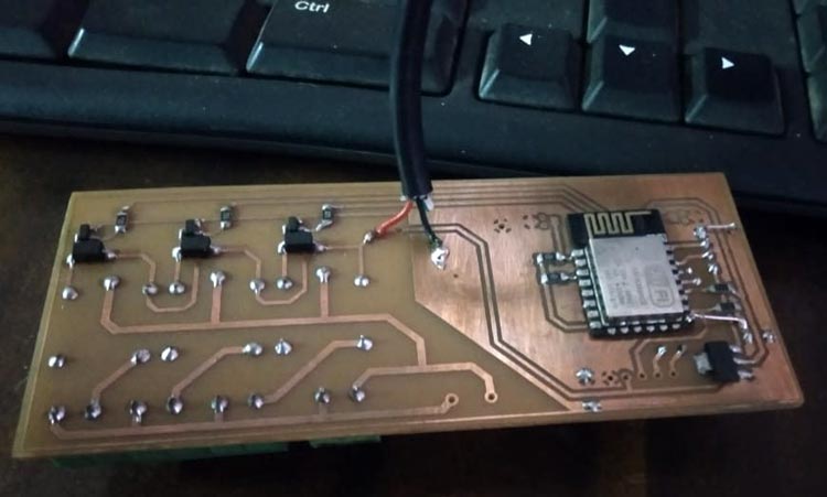
Copper Clad:- I have used copper clad to make homemade PCB as it is very cheap for single PCB.
SMD Components:- I used smd components in this because it makes my PCB smaller and better. And to power the Wi-Fi module of this circuit I have AMS 1117 3.3v is used. Which is a SMD IC. And in this circuit I have used many smd like resistors, power IC, buttons, diodes and etc.
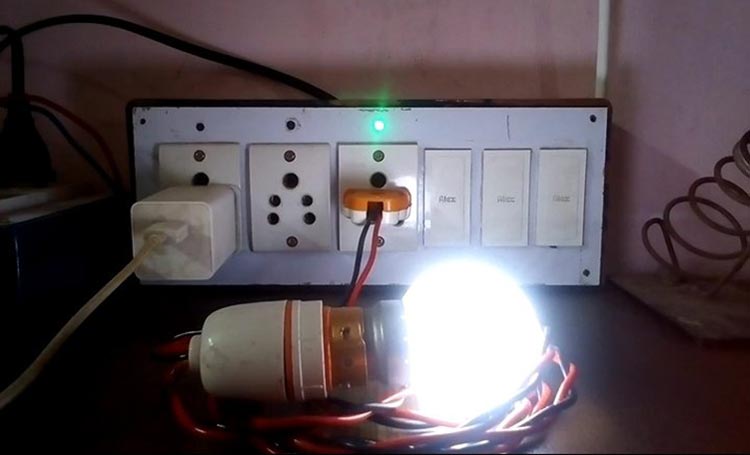
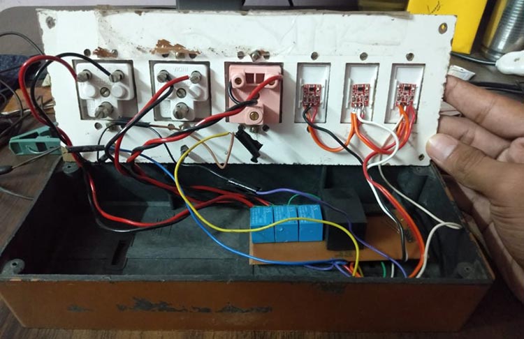
Plug and Dummy Switch of Electric Board:- I am going to use the plug to run my household appliances whose output will come from our Wi-Fi circuit. And I have used a dummy switch to set up the touch sensor
Arduino IDE:- I use Arduino IDE here because it is good and nice software. And it is very good for the programming of embedded systems. Arduino IDE is simple, and the code itself is much easier to comprehend. Another reason Arduino is so popular because there are many people using it which means there's a lot of examples out there to work with.
EasyEDA:- I have used EasyEDA software to design PCB here. It is online software and I can use it from anywhere using the internet. And all the components are easily found in this software. So I like this software. EasyEDA is a very capable online EDA platform that provides users access to all the core functions and tools required to design PCBs and circuits for various applications. It also has a great set of innovative features that even some of the paid EDA programs didn't have until recently. So I like this software.
PyCharm:- For creating Ai Assistance I have used PyCharm IDE for compiling our code. And I choose them because PyCharm provides smart code completion, code inspections, on-the-fly error highlighting and quick-fixes, along with automated code refactoring’s and rich navigation capabilities.
Mediapipe:- Mediapipe is a cross-platform library developed by Google that provides amazing ready-to-use ML solutions for computer vision tasks. OpenCV library in python is a computer vision library that is widely used for image analysis, image processing, detection, recognition, etc
OpenCV-Python:- OpenCV is used for all sorts of image and video analysis, like facial recognition and detection, license plate reading, photo editing, advanced robotic vision, optical character recognition, and a whole lot more. We will be working through many Python examples here.
MIT App Inventor:- App Inventor is a cloud-based tool, which means you can build apps for Android or iOS devices right in your web browser. This website offers all the support you'll need to learn how to build your own apps.
Requests:- The requests library is the de facto standard for making HTTP requests in Python. It abstracts the complexities of making requests behind a beautiful, simple API so that you can focus on interacting with services and consuming data in your application.
AI Home Automation Circuit Diagram

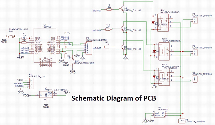
So, our circuit diagram is very simple. I have used Esp12-e in it and to program it I have also kept the pin of RX/TX. Then I have connected 3 pins of Esp12-e with relay and the other 3 pins are kept for the input of the touch sensor. And I have used a Hi-Link power supply to power the entire circuit. Here I also used 2 pin connectors for connecting board wiring. And our circuit diagram is ready. And one thing, I have used some resistors inside it. Which does it to pull up and pull down some pins of esp12e. Circuit Diagram of Board:- The circuit diagram of the board is the connection of the main hardware of our project. Inside which we put the circuit containing our Wi-Fi module. First of all, I connected 3 plugs to our Wi-Fi circuit using wire. And after that, I also connected the touch sensor. And I also put 3 LED lights inside this diagram. Which will tell the status of our plug whether the plug is on or off. And I have taken the input pin of this LED from the input pin of the relay. And finally, I have a 220V power supply connected to our Wi-Fi circuit. And our smart board is ready.

Complete Project Code
#include <ESP8266WiFi.h>
#include <WiFiClient.h>
#include <BlynkSimpleEsp8266.h>
BlynkTimer timer;
#define RELAY_PIN_1      13
#define RELAY_PIN_2      12
#define RELAY_PIN_3      14
#define TOUCH_BUTTON_1    4
#define TOUCH_BUTTON_2    5
#define TOUCH_BUTTON_3    15
int MODE = 0;
int relay1State = LOW;
int relay2State = LOW;
int relay3State = LOW;
int TOUCHButton1State = HIGH;
int TOUCHButton2State = HIGH;
int TOUCHButton3State = HIGH;
// Your WiFi credentials.
// Set password to "" for open networks.
#define AUTH "nm84INtLwBwMXiyoBcIilNWLPwFSBU"
#define WIFI_SSID "ANAND"
#define WIFI_PASS "22102003A"
BLYNK_WRITE(V1)
{
   relay1State = param.asInt(); // assigning incoming value from pin V1 to a variable
  digitalWrite(RELAY_PIN_1, relay1State);
  // process received value
}

BLYNK_WRITE(V2)
{
   relay2State = param.asInt(); // assigning incoming value from pin V2 to a variable
  digitalWrite(RELAY_PIN_2, relay2State);
  // process received value
}

BLYNK_WRITE(V3)
{
   relay3State = param.asInt(); // assigning incoming value from pin V3 to a variable
  digitalWrite(RELAY_PIN_3, relay3State);
  // process received value
}

void with_internet()
{
  if (digitalRead(TOUCH_BUTTON_1) == LOW) {
    if (TOUCHButton1State != LOW) {
      relay1State = !relay1State;
      digitalWrite(RELAY_PIN_1, relay1State);
      Blynk.virtualWrite(V1, relay1State);
    }
    TOUCHButton1State = LOW;
  } else {
    TOUCHButton1State = HIGH;
  }

  if (digitalRead(TOUCH_BUTTON_2) == LOW) {
    if (TOUCHButton2State != LOW) {
      relay2State = !relay2State;
      digitalWrite(RELAY_PIN_2, relay2State);
      Blynk.virtualWrite(V2, relay2State);
    }
    TOUCHButton2State = LOW;
  } else {
    TOUCHButton2State = HIGH;
  }

  if (digitalRead(TOUCH_BUTTON_3) == LOW) {
    if (TOUCHButton3State != LOW) {
      relay3State = !relay3State;
      digitalWrite(RELAY_PIN_3, relay3State);
      Blynk.virtualWrite(V3, relay3State);
    }
    TOUCHButton3State = LOW;
  } else {
    TOUCHButton3State = HIGH;
  }
}

void without_internet()
{
  if (digitalRead(TOUCH_BUTTON_1) == LOW) {
    if (TOUCHButton1State != LOW) {
      relay1State = !relay1State;
      digitalWrite(RELAY_PIN_1, relay1State);
       }
    TOUCHButton1State = LOW;
  } else {
    TOUCHButton1State = HIGH;
  }

  if (digitalRead(TOUCH_BUTTON_2) == LOW) {
    if (TOUCHButton2State != LOW) {
      relay2State = !relay2State;
      digitalWrite(RELAY_PIN_2, relay2State);
       }
    TOUCHButton2State = LOW;
  } else {
    TOUCHButton2State = HIGH;
  }

  if (digitalRead(TOUCH_BUTTON_3) == LOW) {
    if (TOUCHButton3State != LOW) {
      relay3State = !relay3State;
      digitalWrite(RELAY_PIN_3, relay3State);
      }
    TOUCHButton3State = LOW;
  } else {
    TOUCHButton3State = HIGH;
  }
}
void checkBlynk() { // called every 3 seconds by SimpleTimer

  bool isconnected = Blynk.connected();
  if (isconnected == false) {
    MODE = 1;
  }
  if (isconnected == true) {
    MODE = 0;
  }
}

void setup()
{
  // Debug console
  Serial.begin(9600);
  pinMode(15,OUTPUT);

  delay (5000);
  digitalWrite(15,HIGH);
  pinMode(TOUCH_BUTTON_1, INPUT);
  pinMode(RELAY_PIN_1, OUTPUT);

  pinMode(TOUCH_BUTTON_2, INPUT);
  pinMode(RELAY_PIN_2, OUTPUT);

  pinMode(TOUCH_BUTTON_3, INPUT);
  pinMode(RELAY_PIN_3, OUTPUT);
  WiFi.begin(WIFI_SSID, WIFI_PASS);
  while (WiFi.status() != WL_CONNECTED) {
        delay(500);
        Serial.print(".");
    }

  timer.setInterval(3000L, checkBlynk);
  Blynk.config(AUTH);// check if connected to Blynk server every 3 seconds
  //, ssid, pass);

}

void loop()
{
  if (WiFi.status() != WL_CONNECTED)
  {
    WiFi.begin(WIFI_SSID, WIFI_PASS);
  }
  else
  {
    Serial.println(" Connected");
    Blynk.run();
  }
  timer.run(); // Initiates SimpleTimer
  if (MODE == 0)
    with_internet();
  else
    without_internet();
}
