

Batteries come with a certain voltage limit and if the voltage goes beyond the prescribed limits while charging or discharging, the life of the battery get affected or reduced. Whenever we use a battery powered project, sometimes we need to check the battery voltage level, whether it is needed to be charged or replaced. This circuit will help you to monitor the voltage of your battery. This Arduino battery voltage indicator indicates the status of the battery by glowing LEDs on a 10 Segment LED Bar Graph according to the battery voltage. It also shows your battery voltage on the LCD connected to the Arduino.
Material Required
- Arduino UNO
- 10 Segment LED Bar Graph
- LCD (16*2)
- Potentiometer-10k
- Resistor (100ohm-10;330ohm)
- Battery (to be tested)
- Connecting wires
- 12v adapter for Arduino
Circuit Diagram

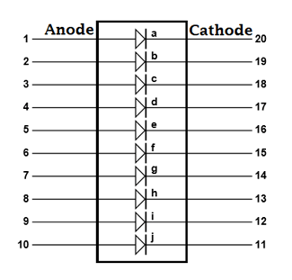
LED Bar Graph
The LED bar graph comes in industrial standard size with a low power consumption. The bar is categorized for luminous intensity. The product itself remains within RoHS compliant version. It has a forward voltage of up to 2.6v. The power dissipation per segment is 65mW. The operating temperature of the LED bar graph is -40℃ to 80℃. There are many application for the LED bar graph like Audio equipment, Instrument panels, and Digital readout display.
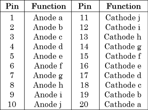
Pin Diagram
Pin Configuration
Arduino Program for Battery Voltage Monitoring:
The complete Arduino code and Demonstration Video is given at the end of this article. Here we have explained some important parts of the code.
Here, we are defining the LCD library and specifying pins of LCD to be used with the Arduino. The analog input is taken from pin A4 for checking the battery voltage. We have set the value as Float to get the voltage up to two decimal.
#include <LiquidCrystal.h>
const int rs = 12, en = 13, d4 = A0, d5 = A1, d6 = A2, d7 = A3;
LiquidCrystal lcd(rs, en, d0, d1, d2, d3);
const int analogPin = A4;
float analogValue;
float input_voltage;
int ledPins[] = {
2, 3, 4, 5, 6, 7, 8, 9, 10, 11
};       // an array of pin numbers to which LEDs are attached
int pinCount = 10;           // the number of pins (i.e. the length of the array)
Setting up LCD and the analog pins (A0, A1, A2, A3) as OUTPUT pins.
void setup()
{
   Serial.begin(9600);     //  opens serial port, sets data rate to 9600 bps
   lcd.begin(16, 2);       //// set up the LCD's number of columns and rows:
   pinMode(A0,OUTPUT);
   pinMode(A1,OUTPUT);
   pinMode(A2,OUTPUT);
   pinMode(A3,OUTPUT);
   pinMode(A4,INPUT);
   lcd.print("Voltage Level");
}
Here, we make a function for using the LED bar graph to use in a simple manner, you can even glow the LEDs by programming them one by one , but the code get lengthy.
void LED_function(int stage)
{
     for (int j=2; j<=11; j++)
   {
    digitalWrite(j,LOW);
   }
   for (int i=1, l=2; i<=stage; i++,l++)
   {
    digitalWrite(l,HIGH);
    //delay(30);
   }
}
//  Conversion formula for voltage
   analogValue = analogRead (A4);
   Serial.println(analogValue);
   delay (1000);
   input_voltage = (analogValue * 5.0) / 1024.0;
   lcd.setCursor(0, 1);
   lcd.print("Voltage= ");
   lcd.print(input_voltage);
   Serial.println(input_voltage);
   delay(100);
According to the value of the input voltage we have given some condition to control the LED bar graph LEDs. The condition you can check below in the code:
if (input_voltage < 0.50 && input_voltage >= 0.00 )
{
digitalWrite(2, HIGH);
delay (30);
digitalWrite(2, LOW);
delay (30);       // when the voltage is zero or low the 1st LED will indicate by blinking
}
else if (input_voltage < 1.00 && input_voltage >= 0.50)
{
LED_function(2);
}
else if (input_voltage < 1.50 && input_voltage >= 1.00)
{
LED_function(3);
}
else if (input_voltage < 2.00 && input_voltage >= 1.50)
{
LED_function(4);
}
else if (input_voltage < 2.50 && input_voltage >= 2.00)
{
LED_function(5);
}
else if (input_voltage < 3.00 && input_voltage >= 2.50)
{
LED_function(6);
}
else if (input_voltage < 3.50 && input_voltage >= 3.00)
{
LED_function(7);
}
else if (input_voltage < 4.00 && input_voltage >= 3.50)
{
LED_function(8);
}
else if (input_voltage < 4.50 && input_voltage >= 4.00)
{
LED_function(9);
}
else if (input_voltage < 5.00 && input_voltage >= 4.50)
{
LED_function(10);
}
}
Working of Battery Voltage Indicator

Battery Voltage Indicator just read the value from Arduino Analog pin and convert it into a digital value by using the Analog to Digital Conversion (ADC) formula. The Arduino Uno ADC is of 10-bit resolution (so the integer values from 0 - 2^10 = 1024 values). This means that it will map input voltages between 0 and 5 volts into integer values between 0 and 1023. So if we multiply input anlogValue to (5/1024), then we get the digital value of input voltage. Learn here how to use ADC input in Arduino. Then the digital value is used to glow the LED bar Graph accordingly.
Also, check this simple Battery level Monitor without any Microcontroller
Complete Project Code
#include <LiquidCrystal.h>
const int rs = 12, en = 13, d0 = A0, d1 = A1, d2 = A2, d3 = A3;

LiquidCrystal lcd(rs, en, d0, d1, d2, d3);

const int analogPin = A4;

float analogValue;

float input_voltage;

int ledPins[] = {

2, 3, 4, 5, 6, 7, 8, 9, 10, 11

};       // an array of pin numbers to which LEDs are attached

int pinCount = 10;           // the number of pins (i.e. the length of the array)

void setup()

{

   Serial.begin(9600);     //  opens serial port, sets data rate to 9600 bps

   lcd.begin(16, 2);       //// set up the LCD's number of columns and rows:

   pinMode(A0,OUTPUT);

   pinMode(A1,OUTPUT);

   pinMode(A2,OUTPUT);

   pinMode(A3,OUTPUT);

   pinMode(A4,INPUT);

   lcd.print("Voltage Level");


}

void LED_function(int stage)

{

     for (int j=2; j<=11; j++)

   {

    digitalWrite(j,LOW);

   }

   for (int i=1, l=2; i<=stage; i++,l++)

   {

    digitalWrite(l,HIGH);

    //delay(30);

   }


}

void loop()

{

//  Conversion formula for voltage

   analogValue = analogRead (A4);

   Serial.println(analogValue);

   delay (1000);

   input_voltage = (analogValue * 5.0) / 1024.0;

   lcd.setCursor(0, 1);

   lcd.print("Voltage= ");

   lcd.print(input_voltage);

   Serial.println(input_voltage);

   delay(100);
if (input_voltage < 0.50 && input_voltage >= 0.00 )

{

digitalWrite(2, HIGH);

delay (30);

digitalWrite(2, LOW);

delay (30);

}

else if (input_voltage < 1.00 && input_voltage >= 0.50)

{

LED_function(2);

}

else if (input_voltage < 1.50 && input_voltage >= 1.00)

{

LED_function(3);

}

else if (input_voltage < 2.00 && input_voltage >= 1.50)

{

LED_function(4);

}

else if (input_voltage < 2.50 && input_voltage >= 2.00)

{

LED_function(5);

}

else if (input_voltage < 3.00 && input_voltage >= 2.50)

{

LED_function(6);

}

else if (input_voltage < 3.50 && input_voltage >= 3.00)

{

LED_function(7);

}

else if (input_voltage < 4.00 && input_voltage >= 3.50)

{

LED_function(8);

}

else if (input_voltage < 4.50 && input_voltage >= 4.00)

{

LED_function(9);

}

else if (input_voltage < 5.00 && input_voltage >= 4.50)

{

LED_function(10);

}
}
Comments
YOur circuit is well constructed and thought out.
Would you tell me what code language is used? Thank you.
nice one
nice project. you have a 5v battery for your project but in my project i have a 24v and 14 amph battery what i do for battery indicator.
i wanted to know if i use a battery (12v-more) than a Function Generator would the battery charge(s) up or it would "only" indicate how many battery left inside the battery? Thank you! .. Waiting for your Response
This battery indicator only measures the voltage across the battery terminals and displays it on the bar graph. If you connect a charger to the battery, the battery will charge and as the battery gets charged the voltage value will increase and also the bar will increase.
Wow thank you for your reply. May i ask again, is the Circuit Diagram correct? I manage to follow the circuit diagram my LCD won't go on even my 10 Segement idk i f the circuit is correct i checked my pins and repeated the process, Does it need a function generator to make my LCD work or would it be okay for the meanwhile w/o a Function Generator to see my work is correct?
May i ask again, if it its okay for the 10 Segment LED Bar Graph, if we use a 7 Segment LED Bar Graph rather than a 10 Segment LED Bar Graph?
Please i need your help, would the LCD print the Voltage in the screen w/o any function generator?
plz help me which resistor is required i have 100ohm or 330 ohm resistor which one is best

I like to build a short distance measurement kit which read mm or less precise distance.
Any suggestion?