
What if we can generate different colors using a single RGB led and make our room’s corner more attractive? So, here is a simple Arduino based color mixing lamp which can change color when there is change in light in the room. So this lamp will automatically will changes its color according to the light conditions in the room.
Every color is the combination of Red, Green and Blue color. So we can generate any color by using red, green and blue colors .So, here we will vary PWM i.e. intensity of light on LDRs. That will further changes the intensity of red, green and blue color in RGB LED, and different colors will be produced.
Below table shows the color combinations with respective change in duty cycles.
Materials required:
- 1 x Arduino UNO
- 1 x Breadboard
- 3 x 220-ohm resistors
- 3 x 1-kilohm resistors
- Jumper wires
- 3 x LDRs
- 3 x colored strips (red, green, blue)
- 1 x RGB LED
LDR:
We will use photoresistor (or light-dependent resistor, LDR, or photo-conductive cell) here in this circuit. LDRs are made from semiconductor materials to enable them to have their light-sensitive properties. These LDRs or PHOTO RESISTORS works on the principle of “Photo Conductivity”. Now what this principle says is, whenever light falls on the surface of the LDR (in this case) the conductance of the element increases or in other words, the resistance of the LDR falls when the light falls on the surface of the LDR. This property of the decrease in resistance for the LDR is achieved because it is a property of semiconductor material used on the surface.
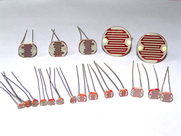
Here three LDR sensors are used to control the brightness of individual Red, Green and Blue LED inside RGB Led. Learn more about controlling LDR with Arduino here.
RGB LED:
There are two types of RGB LEDs, one is common cathode type (common negative) and other is common anode type (common positive) type. In CC (Common Cathode or Common Negative), there will be three positive terminals each terminal representing a color and one negative terminal representing all three colors.


In our circuit we are going to use CA (Common Anode or Common Positive) type. In Common Anode type, if we want RED LED to be ON in, we need to ground the RED LED pin and power the common positive. The same goes for all the LEDs. Learn here to interface RGB LED with Arduino.
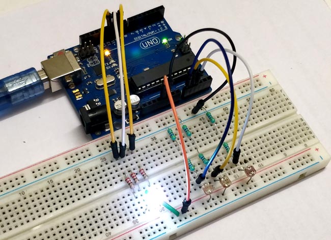
Circuit Diagram:

The complete circuit diagram of this project is given above. The +5V and ground connection shown in the circuit diagram can be obtained from the 5V and ground pin of the Arduino. The Arduino itself can be powered from your laptop or through the DC jack using a 12V adapter or 9V battery.
We will use PWM to change brightness of RGB led. You can learn more about PWM here. Here are some PWM examples with Arduino:
Programming Explanation:
First, we declare all the inputs and output pins as shown below.
const byte red_sensor_pin = A0;
const byte green_sensor_pin = A1;
const byte blue_sensor_pin = A2;
const byte green_led_pin = 9;
const byte blue_led_pin = 10;
const byte red_led_pin = 11;
Declare initial values of sensors and leds as 0.
unsigned int red_led_value      = 0;
unsigned int blue_led_value     = 0;
unsigned int green_led_value    = 0;
unsigned int red_sensor_value   = 0;
unsigned int blue_sensor_value  = 0;
unsigned int green_sensor_value = 0;

void setup() {
    pinMode(red_led_pin,OUTPUT);
    pinMode(blue_led_pin,OUTPUT);
    pinMode(green_led_pin,OUTPUT);
    Serial.begin(9600);
}
In loop section, we will take output of three sensors with analogRead(); function and store in three different variables.
void loop() {
    red_sensor_value = analogRead(red_sensor_pin);
    delay(50);
    blue_sensor_value = analogRead(blue_sensor_pin);
    delay(50);
    green_sensor_value = analogRead(green_sensor_pin);
Print those values onto the serial monitor for debugging purpose
    Serial.println("Raw Sensor Values:");
    Serial.print("\t Red: ");
    Serial.print(red_sensor_value);
    Serial.print("\t Blue: ");
    Serial.print(blue_sensor_value);
    Serial.print("\t Green: ");
    Serial.println(green_sensor_value);
We will get 0-1023 values from the sensors but our Arduino PWM pins have 0-255 values as output. So we have to convert our raw values to 0-255. For that we have to divide raw values by 4 OR simply we can use mapping function of Arduino to convert these values.
   red_led_value   = red_sensor_value / 4;   // define Red LED
   blue_led_value  = blue_sensor_value / 4;  // define Blue LED
   green_led_value = green_sensor_value / 4; // define Green Led
Print mapped values to serial monitor
    Serial.println("Mapped Sensor Values:");
    Serial.print("\t Red: ");
    Serial.print(red_led_value);
    Serial.print("\t Blue: ");
    Serial.print(blue_led_value);
    Serial.print("\t Green: ");
    Serial.println(green_led_value);
Use analogWrite() to set output for RGB LED
  analogWrite(red_led_pin,red_led_value);   // indicate red LED
  analogWrite(blue_led_pin,blue_led_value);  // indicate blue LED
  analogWrite(green_led_pin,green_led_value); // indicate green
Working of Arduino Color Mixing Lamp:
As we are using three LDR’s so, when light incident on these sensors ,it’s resistance changes as a result voltages also changes at analog pins of Arduino which is acting as a input pins for sensors.
When intensity of light changes on these sensors, it’s respective led in RGB will glow with amount of resistance changing and we have different color mixing in RGB led using PWM.
Complete Project Code
const byte red_sensor_pin = A0;

const byte green_sensor_pin = A1;

const byte blue_sensor_pin = A2;

const byte green_led_pin = 9;

const byte blue_led_pin = 10;

const byte red_led_pin = 11;
unsigned int red_led_value      = 0;

unsigned int blue_led_value     = 0;

unsigned int green_led_value    = 0;

unsigned int red_sensor_value   = 0;

unsigned int blue_sensor_value  = 0;

unsigned int green_sensor_value = 0;
void setup() {

    pinMode(red_led_pin,OUTPUT);

    pinMode(blue_led_pin,OUTPUT);

    pinMode(green_led_pin,OUTPUT);

    Serial.begin(9600);

}
void loop() {

    red_sensor_value = analogRead(red_sensor_pin);

    delay(50);

    blue_sensor_value = analogRead(blue_sensor_pin);

    delay(50);

    green_sensor_value = analogRead(green_sensor_pin);

    // print those values onto the serial monitor

    Serial.println("Raw Sensor Values:");

    Serial.print("\t Red: ");

    Serial.print(red_sensor_value);

    Serial.print("\t Blue: ");

    Serial.print(blue_sensor_value);

    Serial.print("\t Green: ");

    Serial.println(green_sensor_value);

    // convert from 0-1023 to 0-255

    red_led_value   = red_sensor_value / 4;   // define Red LED

    blue_led_value  = blue_sensor_value / 4;  // define Blue LED

    green_led_value = green_sensor_value / 4; // define Green LEd

    // print mapped values to serial monitor

    Serial.println("Mapped Sensor Values:");

    Serial.print("\t Red: ");

    Serial.print(red_led_value);

    Serial.print("\t Blue: ");

    Serial.print(blue_led_value);

    Serial.print("\t Green: ");

    Serial.println(green_led_value);

    // use analogWrite() to set output for RGB LED

    analogWrite(red_led_pin,red_led_value);   // indicate red LED

    analogWrite(blue_led_pin,blue_led_value);  // indicate blue LED

    analogWrite(green_led_pin,green_led_value); // indicate green

}

I recently got a new Arduino unor3 and wanted to try out something basic like this. I thought I had a 4 pin RGB LED but i only had a 3 pinned one (that doesn't have a like positive). So i tried it with 3 diffent LEDs (Red, Green and Blue) and set them up as it would be a normal 4 pin RGB. Once all set up all the LEDs just stayed on even arfer pressing the reset button. I looked at the serial print and it was quite fast, but once I stopped autoscroll I saw results like; Uncovered - Raw - 260 to 320, Mapped - 55 to 80, Covered - Raw - 120 to 130, Mapped - 20 - 30. This was all seeming fine but the LEDs output did not change. It may be my LDRs fault, but some insight would be nice if you had any ideas. Thanks - Heath