
By Varun Sontakke
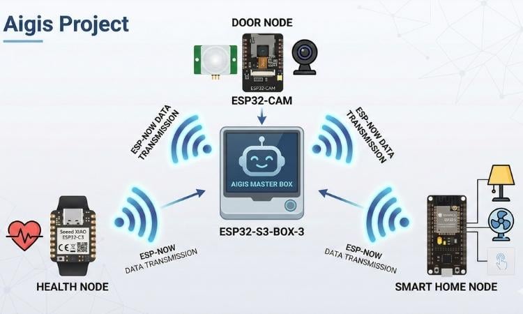
An Edge-AI Ecosystem merging Robotics, Health, Security, and Home Automation via ESP-NOW.
Aigis is not just another smart assistant, it is a distributed Edge-AI Ecosystem designed to bridge the gap between human interaction and smart home automation. While most current smart home devices act as isolated "islands"—where your doorbell doesn't talk to your health tracker, and your lights don't know if you've fallen—Aigis serves as the Bipedal Heart of the home.
It integrates four distinct, specialized nodes into a single, cohesive guardian system that prioritizes privacy, local processing, and physical companionship.
The Problem: The Fragmented Smart Home
Modern families face a dual challenge, ensuring safety for aging grandparents while providing engaging interaction for young children. Existing smart homes are often soulless fragmented apps that elders find confusing and kids find boring. A true smart home shouldn't just be a switch; it should be a guardian.
Modern smart homes suffer from three major issues:
- Privacy Concerns: Most voice assistants and cameras rely on the cloud, sending sensitive personal data to external servers.
- High Latency: Cloud-dependency causes delays in critical scenarios, like fall detection or security alerts.
- Lack of Personality: Smart devices are often invisible or "boxy," making them unintuitive and unapproachable for children or the elderly.
The Solution: Distributed Edge Intelligence
Aigis solves these challenges by utilizing TinyML and ESP-NOW protocols to keep all processing on-device. By moving the "brain" to the edge, Aigis provides 10x faster response times and 100% data privacy.
The Master Brain An ESP32-S3-BOX-3 that handles Voice AI and orchestrates the entire network while displaying a range of emotive expressions. while siting on a robot body.
The Physical Interface A 3D-printed Otto DIY bipedal body controlled by an Arduino Nano, giving the Aigis a physical presence that can dance, move, and interact with kids and play story for them.
The Door Node An ESP32-CAM with a PIR sensor that uses Edge AI to recognize family members or servants for old age people and alert the aigis. also allows to control door locking and unlocking.
The Health Node A wearable Seeed XIAO ESP32-C3 for real-time fall detection and heart rate monitoring . on any anomaly it alerts Aigis and send SMS alert via circuit digest cloud sms API.
The Home Node A NodeMCU ESP32-S that integrates manual touch switches with automated relays using advanced XOR (stair case ) logic also it controls fan speed without any dependency on any mobile app just control with voice command.
Core Innovation Pillars
- Privacy First: No voice or video data ever leaves your local network.
- Low-Latency Interaction: By using ESP-NOW instead of standard Wi-Fi for node communication, the system achieves near-instantaneous alerts.
- Emotive Robotics: By combining the ESP32-S3-BOX-3 screen with a bipedal body, Aigis transitions from a "tool" to a "companion."
- Smart Home: By implementing localized XOR logic, the system allows seamless appliance control via both manual touch and digital voice commands without state conflicts.
Kids reaction :
Main functionality is there but making smart home and wearables more interactive is what is amazing part of this project look into this video how a kid reacts when aigis do some dance moves.
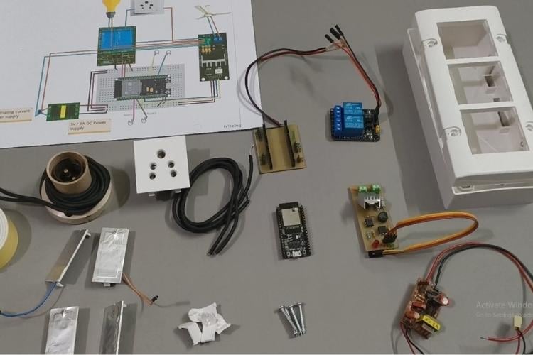
II. Hardware Components List:
Digi key link of list : Link This link is having all components for purchase to make this project its like BOM.
Software apps and online services
- Fritzing : for making circuit diagrams
- Arduino IDE: for coding Door node , smart home node and health node.
- Fusion 360 : for making 3D designs for casing for Door node and Health Node
- Tinker cad : For making body and head of Aigis robot.
- Visual Studio code with ESP IDF extension
- Easy Eda : For making schematics and designing of PCBs
- Bambu studio : For configuring the printing of casing for all nodes.
These are the tools that are online available free to use just search the name of software you need to use and you can get lot of details about to use them for the purpose i have used for Aigis project.
Hand tools and fabrication machines:
- Soldering station
- 3D printer
- Drilling machine
- PCB etching station
- Voltmeter
- Bench vise
These tools helped me to make hardware much better and with ease all tools are also mentioned in components and you can take a look there and buying link is also mentioned in that.
Components Required
| Component Name | Quantity | Datasheet/Link |
| ESP 32 S3 Box3 | 1 | View Datasheet |
| Xiao ESP 32 C3 | 1 | View Datasheet |
| Node MCU ESP 32 S | 1 | View Datasheet |
| ESP 32 CAM | 1 | View Datasheet |
| Arduino Nano | 1 | View Datasheet |
| MAX 30102 | 1 | View Datasheet |
| MPU 6050 (GY 521) | 1 | View Datasheet |
| 3.7v / 135mAh Lipo battery | 1 | View Datasheet |
| Buzzer 5v | 2 | View Datasheet |
| Elastic Band 100mm long | 1 | View Datasheet |
| 5v / 2A AC to DC Micro USB adapte | 1 | View Datasheet |
| PIR Sensor Module | 1 | View Datasheet |
| 5V Single-Channel Relay Module | 1 | View Datasheet |
| Micro USB Female Power Cable Panel Mount | 1 | View Datasheet |
| Solenoid for Electric Door Lock | 1 | View Datasheet |
| FT232RL USB TO TTL 5V 3.3V | 1 | View Datasheet |
| Female 2.1*5.5mm for DC Power Jack | 2 | View Datasheet |
| 5V Dual-Channel Relay Module | 1 | View Datasheet |
| AC Dimmer module | 1 | View Datasheet |
| 5V / 1A Ac to DC converter module | 1 | View Datasheet |
| Wall Mounted Electric Boxes Dual Socket and Dual Switch | 1 | View Datasheet |
| 5 Pin AC shocket | 1 | View Datasheet |
| Aluminium foil | 1 | View Datasheet |
| Switch cap | 4 | View Datasheet |
| Mini BreadBoard | 1 | View Datasheet |
| Li-ion 3.7v 2000mAh battery 18650 | 2 | View Datasheet |
| Battery 2 x 18650 Cell Box | 1 | View Datasheet |
| Servo Motor SG-90 | 4 | View Datasheet |
| Bread Board Jumper wires F-F , M-F , M-M each size | 10 | View Datasheet |
| Header pin male and female each | 20 | View Datasheet |
| PCB Glass epoxy 6x4 | 1 | View Datasheet |
| Nose Plier | 1 | View Datasheet |
| Wire Cutter | 1 | View Datasheet |
| Screw driver set | 1 | - |
| Glue gun | 1 | View Datasheet |
| Sand paper 150 | 1 | View Datasheet |
| White and Black PLA+ 1kg spool | 2 | - |
| USB C type cables | 2 | - |
| Double sided tape | 1 | View Datasheet |
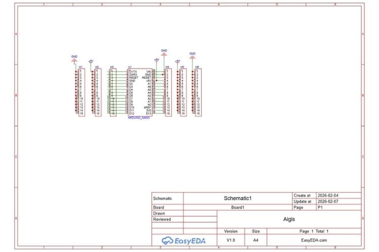
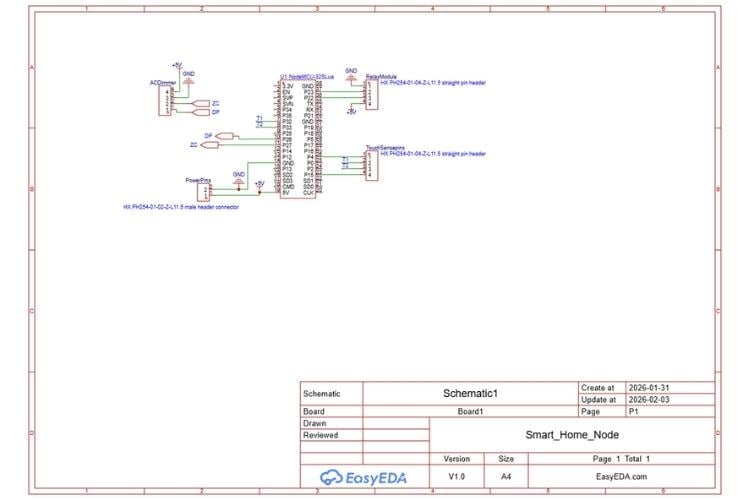
Circuit Diagram
III. Circuit Diagram & System Architecture:
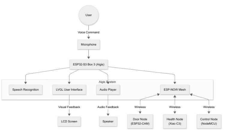
The hardware architecture of Project Aigis is modular. Instead of a single complex circuit, This system architecture diagram illustrates the complete Aigis ecosystem, a distributed edge-AI platform centered around the Aigis Master Robot. The robot itself is a dual-processor unit, with an ESP32-S3-BOX-3 acting as the primary "brain" for voice AI and user interface, communicating via I2C with an Arduino Nano that acts as the dedicated "body controller" for physical movements. This central hub orchestrates three specialized peripheral nodes through the ultra-low-latency ESP-NOW (2.4GHz) wireless protocol: the Door Node (ESP32-CAM for vision and solenoid access), the Health Node (a wearable XIAO ESP32-C3 with IMU and bio-sensors), and the Smart Home Node (a NodeMCU ESP32-S managing high-voltage appliances via relays and dimmers).
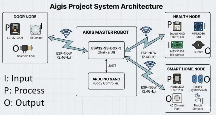
Below are the circuit details and connection diagrams for each individual node.
1. Aigis Master & Body (The Robot)

Description:
This circuit represents the central "Hub" of the ecosystem. It utilizes a Master-Slave architecture to separate high-level AI processing from low-level motor control.
- The Brain (Master): The ESP32-S3-BOX-3 handles voice recognition, facial expressions (LCD), and wireless ESP-NOW communication with other nodes.
- The Spinal Cord (Slave): An Arduino Nano acts as a dedicated servo controller for the Otto DIY bipedal chassis.
- Communication: The two boards communicate via UART (Serial). The ESP32 sends action commands (e.g., "Walk", "Dance") to the Nano, which executes the specific servo movements.
Connection Details:
- Power Supply:
- Source: 2x 18650 Li-Ion Batteries (7.4V total) connected to a slide switch.
- Distribution: Power is regulated to 5V (if using a buck converter/regulator, though the diagram shows direct battery power to the rails—ensure your servos can handle the voltage, or use the Nano's VIN for regulation). The ESP32-S3-BOX-3 and Arduino Nano share a Common Ground (GND).
- Inter-Board Communication (UART):
- ESP32 TX (G42) to Arduino Nano RX (D0) (Sends commands to body).
- One wire is enough as its just one way data transmission UART based.
- Actuators (Otto DIY Bipedal Config):
- Left Leg Servo (Signal): Connected to Arduino Nano D2.
- Right Leg Servo (Signal): Connected to Arduino Nano D3.
- Left Foot Servo (Signal): Connected to Arduino Nano D4.
- Right Foot Servo (Signal): Connected to Arduino Nano D5.
- Note: All servos connect to the external 7.2V/GND Power Rail, not the Arduino 5V pin, to prevent brownouts.
- Left Leg Servo (Signal): Connected to Arduino Nano D2.
- Audio Feedback:
- Piezo Buzzer (+): Connected to Arduino Nano D13 for movement sounds.
- Piezo Buzzer (-): Connected to GND.
- Piezo Buzzer (+): Connected to Arduino Nano D13 for movement sounds.
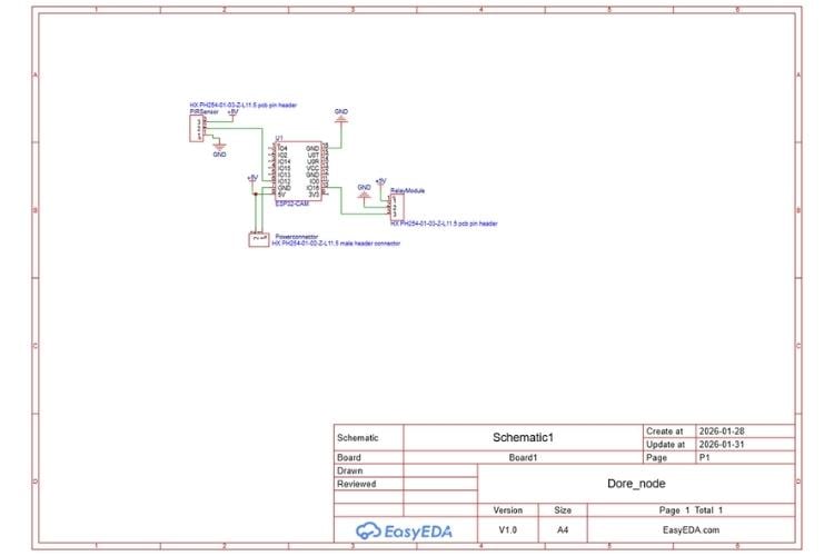
2. The Door Node (The Eyes)
Description:
The Door Node acts as the first line of defense. It combines computer vision with physical security.
- The Guard: A PIR Motion Sensor constantly scans for presence. This is an "Interrupt" device—it keeps the system in low power until movement is detected.
- The Vision: Once awoken, the ESP32-CAM captures frames and runs a TinyML model to check if the face belongs to a known family member.
- The Gatekeeper: If authentication is successful (or upon command from the Aigis Master), the Relay Module triggers a high-power 12V Solenoid Lock to physically open the door.
Connection Details:
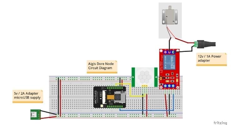
- Power Architecture (Dual Rail):
- Logic Power: A 5V / 2A Micro USB Adapter powers the breadboard rails, feeding the ESP32-CAM, PIR, and Relay logic.
- Lock Power: A separate 12V / 1A Adapter is connected directly to the Relay's switching side to drive the Solenoid Lock. This isolation prevents voltage spikes from the lock crashing the ESP32.
- Logic Power: A 5V / 2A Micro USB Adapter powers the breadboard rails, feeding the ESP32-CAM, PIR, and Relay logic.
- Sensor & Actuator Connections:
- PIR Motion Sensor:
- VCC: Connected to 5V Rail.
- GND: Connected to GND Rail.
- OUT (Signal): Connected to ESP32-CAM GPIO 13 (Yellow Wire).
- VCC: Connected to 5V Rail.
- Relay Module (Control Side):
- VCC (+): Connected to 5V Rail.
- GND (-): Connected to GND Rail.
- IN (Signal): Connected to ESP32-CAM GPIO 12 (Blue Wire).
- VCC (+): Connected to 5V Rail.
- Solenoid Lock (High Power Side):
- Circuit: The 12V Positive goes into the Relay COM (Common) port.
- Circuit: The Relay NO (Normally Open) port connects to the Solenoid Positive.
- Circuit: The Solenoid Negative goes directly to the 12V Adapter Ground.
- Circuit: The 12V Positive goes into the Relay COM (Common) port.
- PIR Motion Sensor:
3. The Health Node (The Shield)
Description:
The Health Node acts as a personal guardian for the user. It is a battery-powered wearable device designed to monitor vital signs and physical safety.
- Core Controller: The Seeed XIAO ESP32-C3 was chosen for its thumb-sized footprint and built-in Wi-Fi/Bluetooth capabilities.
- Power: It runs on a compact 3.7V LiPo Battery, making it completely wireless.
- Sensors: It uses a shared I2C Bus to connect two sensors: the MPU6050 (for detecting sudden falls via accelerometer data) and the MAX30102 (for monitoring Heart Rate and SpO2 levels).
- Alert: A Piezo Buzzer provides immediate local feedback (beeping) if a fall is detected, while the ESP32-C3 simultaneously sends an alert to the Aigis Master.
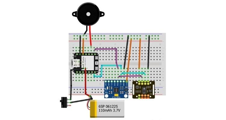
Connection Details:
- Power Circuit:
- 3.7V LiPo Battery (-): Connected to Slide Switch (Pin 1).
- Slide Switch (Pin 2): Connected to XIAO GNDBat-
- 3.7V LiPo Battery (+): Connected to XIAO VBat+ Pin
- 3.7V LiPo Battery (-): Connected to Slide Switch (Pin 1).
- I2C Sensor Bus (MPU6050 & MAX30102 Shared):
- VCC (Both Sensors): Connected to XIAO 3V3 Pin (Regulated output).
- GND (Both Sensors): Connected to Common GND.
- SDA (Data): Connected to XIAO D8 (SDA).
- SCL (Clock): Connected to XIAO D7 (SCL).
- VCC (Both Sensors): Connected to XIAO 3V3 Pin (Regulated output).
- Output (Alerts):
- Piezo Buzzer (+): Connected to XIAO D9 .
- Piezo Buzzer (-): Connected to GND.
- Piezo Buzzer (+): Connected to XIAO D9 .
4. Smart Home Node (The Hands)
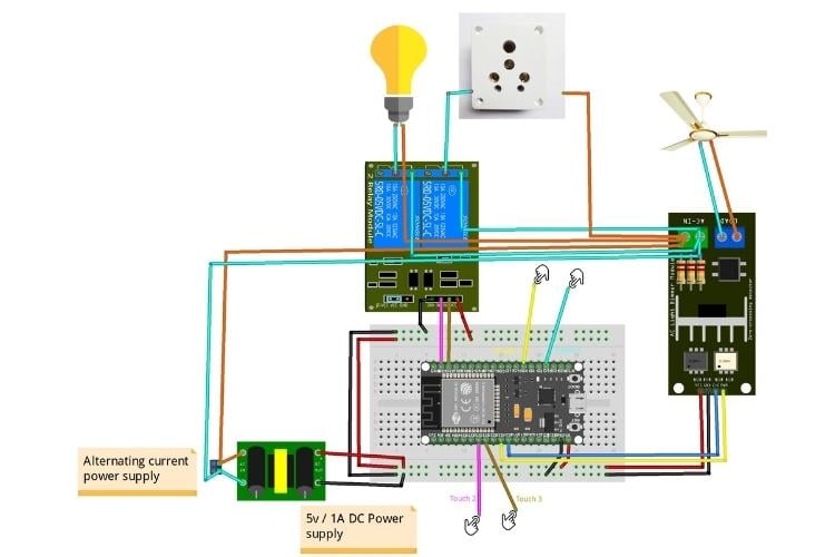
Description:
The Smart Home Node is designed to retrofit into standard switchboards. It provides "Hybrid Control," allowing appliances to be controlled both physically (via touch) and digitally (via Aigis).
- Controller: A NodeMCU ESP32-S handles the logic.
- Power System: It uses an isolated AC-to-DC 5V Buck Converter to power the ESP32 directly from the mains, eliminating the need for external USB adapters.
- Actuation:
- 2-Channel Relay Module: Switches the Light Bulb and Power Socket.
- AC Light Dimmer: Uses Zero-Crossing detection to control the speed of the Ceiling Fan.
- 2-Channel Relay Module: Switches the Light Bulb and Power Socket.
- Manual Input: Four Capacitive Touch Points (wires connected to metal plates behind the switchboard) allow the user to toggle devices manually.
Connection Details:
- High Voltage Side (AC Mains):
- Input: 220V AC Mains (Live/Neutral) connects to the AC-DC Buck Converter Input and distributes Live to the Relays/Dimmer.
- Input: 220V AC Mains (Live/Neutral) connects to the AC-DC Buck Converter Input and distributes Live to the Relays/Dimmer.
- Output (Appliances):
- Light Bulb: Connected via Relay 1 NO (Normally Open).
- Power Socket: Connected via Relay 2 NO.
- Ceiling Fan: Connected via the Dimmer Module LOAD terminal.
- Light Bulb: Connected via Relay 1 NO (Normally Open).
- Low Voltage Logic (ESP32 Connections):
- Relay Module
- IN1 (Light) to GPIO 23 (NodeMCU ESP32)
- IN2 (Socket) to GPIO 22 (NodeMCU ESP32)
- IN1 (Light) to GPIO 23 (NodeMCU ESP32)
- AC Dimmer
- Z-C (Zero Cross) to GPIO 27 (NodeMCU ESP32)
- PWM (Dimming) to GPIO 26 (NodeMCU ESP32)
- Z-C (Zero Cross) to GPIO 27 (NodeMCU ESP32)
- Touch Sensors
- Touch Sensor 1 (Light Toggle) to GPIO 4 (NodeMCU ESP32)
- Touch Sensor 2 (Socket Toggle) to GPIO 33 (NodeMCU ESP32)
- Touch Sensor 3 (Fan Toggle) to GPIO 32 (NodeMCU ESP32)
- Touch Sensor 4 (Speed Control) to GPIO 15 (NodeMCU ESP32)
- Touch Sensor 1 (Light Toggle) to GPIO 4 (NodeMCU ESP32)
- Power Connections
- 5V Input to VIN (From Buck Converter)
- GND to GND (Common Ground)
- 5V Input to VIN (From Buck Converter)
Disclaimer: Do follow connection well after connection do check the continuity with multimeter so that no short circuit is happening, also be careful as AC supply is involved in this project wear slippers and hand gloves while doing connection handle wire with nose pliers.
IV. Step-by-Step Build Guide: Node-by-Node:
Disclaimer: all designs are prototype based only will upgrade later and well posted in GitHub with version control. you will get options to change design and also with mentioned used software you can further use base hardware design file to customize as per your application and usage.
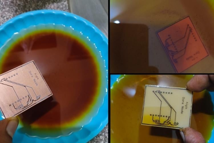
Manual PCB Fabrication (The Toner Transfer Method)
Manual PCB fabrication allows for rapid iteration of the Door, Health, and Home nodes. By following the "The Engineering Projects" structured workflow, we ensure high trace precision and reliable soldering pads. This process you can also skip and use given Gerber files to directly print order from a PCB manufacturer
1. Materials and Tools Required
- Copper Clad Board: Single-sided glass epoxy PCB board
- Laser Printer: (Note: Inkjet printers will not work for toner transfer). use laser printer
- black and white toner printer
- Glossy Paper: High-gloss magazine paper 180 gsm or specialized PCB transfer paper.
- Chemicals: Ferric Chloride (FeCl_3) for etching and Acetone for cleaning.
- Tools: Household iron, mini drill press, fine sandpaper (150+ grit).
2. Step-by-Step Fabrication Process
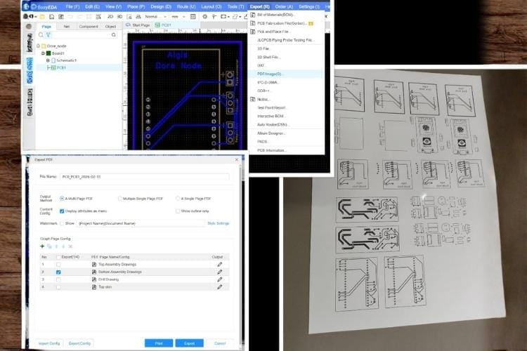
Step 1: Design and Mirror Printing
The first step is to design the PCB layout using software EasyEDA. Once finalized, the layout must be printed in Mirror Image on glossy paper. Ensure the printer settings are set to "High Toner Density" for the best results.
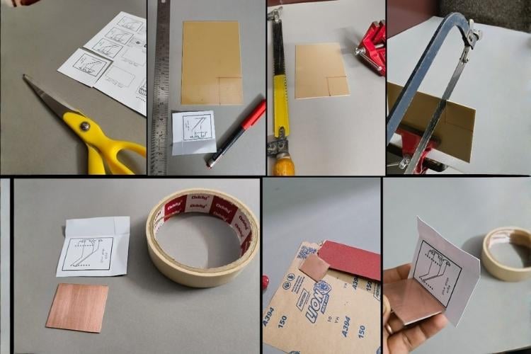
Step 2: Copper Board Preparation
Cut the copper-clad board to the required size for the node. Use fine sandpaper to scrub the copper surface until it is bright and reflective. This removes oxidation and allows the toner to bond effectively. Clean the surface thoroughly with isopropyl alcohol afterward.
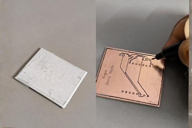
Step 3: Design Transfer (Heat Application)
Align the printed layout face-down onto the copper side of the board. Using a household iron set to maximum heat (no steam), apply firm, even pressure across the paper for 5 to 8 minutes. The heat melts the toner, fusing it onto the copper surface.

Step 4: Paper Removal
Soak the heated board in a tray of warm water for about 10 minutes. Once the paper is soft, gently peel and rub it away. The black toner should now be clearly visible on the copper, forming the protective layer for your circuit traces. if some missing trace happen use marker pen to mark them.
Step 5: Chemical Etching
Submerge the board into a solution of Ferric Chloride. Agitate the container gently to speed up the reaction. The chemical will dissolve all the exposed copper, leaving only the traces protected by the toner. Once the unwanted copper is gone, rinse the board in clean water immediately. also use hot boiling water to speed up and also use plastic tray no metal tray.
Step 6: Toner Removal and Cleaning
Use a cloth soaked in Acetone or a sand paper to wipe away the black toner. This reveals the shiny copper traces beneath. At this stage, the circuit is physically formed on the board.
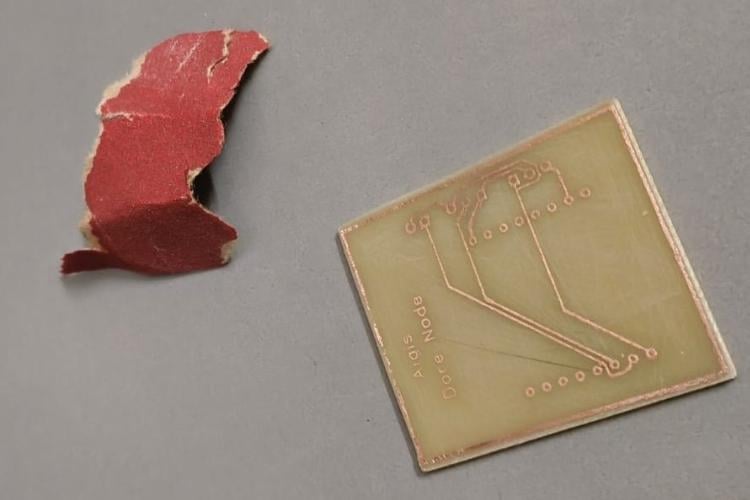
Step 7: Drilling and Finishing
Use a mini PCB drill (typically 0.8mm to 1mm bits) to create holes for the through-hole components like the ESP32 headers and relay pins. Finally, apply a thin layer of solder flux to prevent oxidation before assembly.
Here will start combining the PCB, 3D designs and molding each part of project in casing and structure. again PCB making is tedious but it gives opportunity for customization , you can also explore online PCB manufacturing platform as well i have shared Gerber files as well.
A) Aigis Master Robot (The Brain & Body)
This node is the primary interface of the project, combining the expressive ESP32-S3-BOX-3 head with the bipedal Otto DIY body.
1. 3D Printing & Mechanical Preparation
To build the Aigis body, you need a set of bipedal parts that offer stability and a mounting point for the "Brain." so using Otto DIY opensource plat form and modified the design of it .
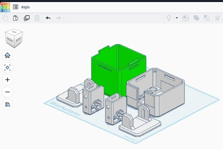
- Standard Otto Parts: Print the following standard Otto DIY components:
- 2x Foot (Left and Right).
- 2x Legs.(Left and Right).
- 1x Bipedal Body.
- 1x Head
- Print Settings:
- Material: PLA (for rigidity and ease of printing).
- Infill: 20% (standard for Otto parts).
- Resolution: 0.15mm or 0.2mm for a balance of speed and detail.
- Slicer : I have used Bambu studio slicer for printing this as per these settings in A1 mini printer
I have attached the STL file of this design as the name as Aigis_3D file.
2. PCB & Circuitry
Aigis Master uses a dual-controller setup where the ESP32-S3-BOX-3 acts as the Master and the Arduino Nano as the Slave.
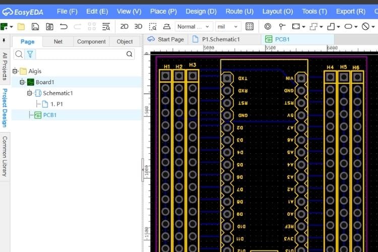
- Protocol: They communicate via the UART protocol, allowing the Master to send complex movement commands to the motor controller.
- Custom Shield/PCB: Use a custom PCB or an Arduino Nano Expansion Shield to manage the wiring for the four SG90 servos.
- Power Management: Ensure a common ground between the ESP32 head and the Nano body to maintain UART signal integrity.
You can use the Gerber file that i have attached as Aigis_PCB to manufacture this PCB
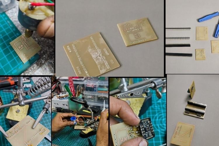
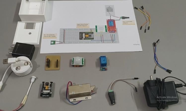
3. Hardware Assembly Steps
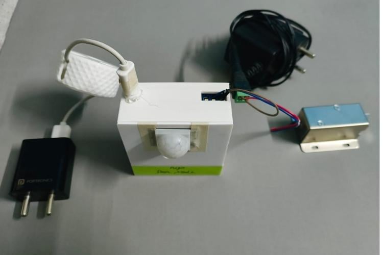
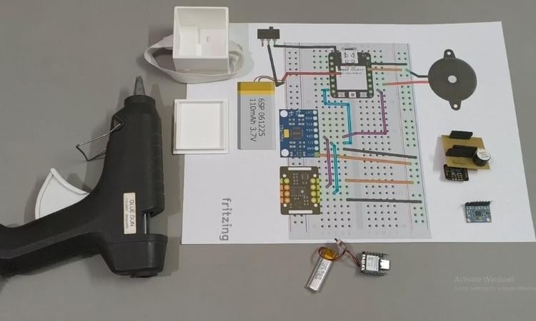
For this assembly you need the below mentioned components in below image:
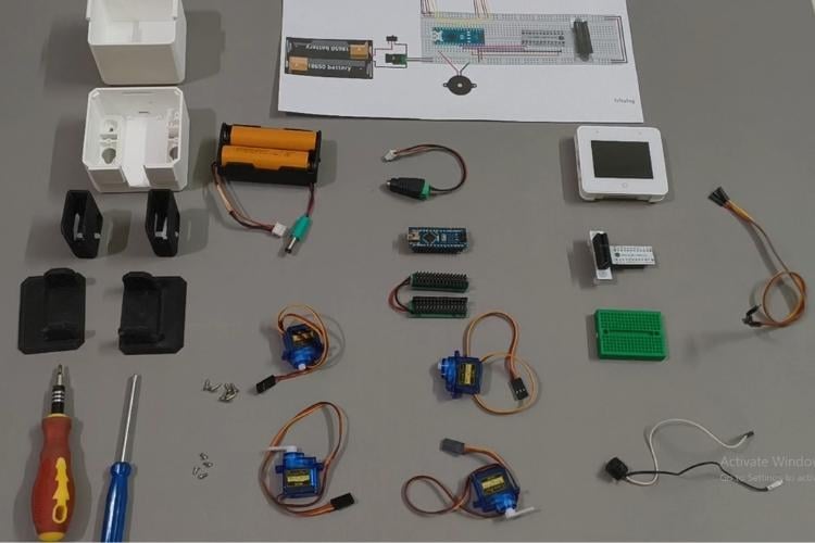
- Servo Calibration: Before mounting, center all four SG90 servos to 90° using a servo tester or a calibration sketch.
- for calibration tutorial follow this video https://youtu.be/jgk8L8_pWiU?si=f0K-ZGHUNyxf2Tp-
- Will also show you in code section how to calibrate it and all code for calibration is given in the documents folder .
- for calibration tutorial follow this video https://youtu.be/jgk8L8_pWiU?si=f0K-ZGHUNyxf2Tp-
- Leg & Foot Assembly: Insert the servos into the 3D-printed feet and legs, securing them with the provided screws.
- Body Mounting: Attach the legs to the main chassis. Route the servo cables through the interior slots to keep the internal wiring clean.
- Connecting the "Brain": Use the mini bread board adn bread adapter of the ESP32-S3-BOX-3 onto the Body. Connect the SDA and SCL pins of the BOX-3 to the corresponding pins on the Arduino Nano for I2C communication as mentioned in circuit diagram section.
- Place PCB on head part of it and paste it with the use of double sided tape.
4. Build Video Reference
Check this video i have given all steps in very detail you just need to follow it up.
Aigis Assembly video tutorial link: https://www.youtube.com/watch?v=Vk-rMrMnXJ4
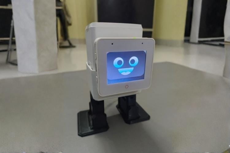
Keep in mind while connecting wires RX of Arduino nano will connect to G42 pin of ESP32 S3 Box 3 bread.
5. Final look of Aigis Robot:
B) The Door Node (The Eyes & Gatekeeper)
The Door Node is a standalone security unit that identifies visitors and manages physical access via a solenoid lock.
1. 3D Printing & Mechanical Preparation
Because this node is often mounted near a doorway, the enclosure needs to be compact and secure.
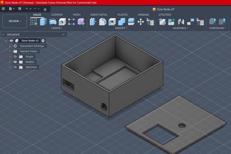
- ESP32-CAM Housing: A custom 3D-printed case designed with a cutout for the camera lens and a front-facing slot for the PIR motion sensor.
- Print Settings:
- Material: PETG (recommended for better durability if mounted near an exterior door) or PLA.
- Infill: 20% (standard for Otto parts).
- Resolution: 0.15mm or 0.2mm for a balance of speed and detail.
- Slicer : I have used Bambu studio slicer for printing this as per these settings in A1 mini printer
I have attached the STL file of this design as the name as Doore_Node_Aigis_3D file.
2. PCB & Circuitry (Power & Switching)
The circuit for this node must handle two different voltage levels safely.
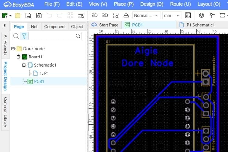
- Power Rail: A custom PCB or perf-board layout that separates the 5V logic (ESP32-CAM, PIR and relay module)
- Relay Isolation: The relay acts as the bridge, allowing the low-power ESP32-CAM to trigger the 12V lock without risking back-EMF damage to the microcontroller.
- Signal Routing: Short, shielded traces for the PIR signal to prevent false triggers in a noisy environment.
You can use the Gerber file that i have attached as Door_Node_Aigis_PCB to manufacture this PCB
3. Hardware Assembly Steps
- PIR Installation: Press-fit the PIR sensor into the 3D-printed front panel and connect it to GPIO 13 on the ESP32-CAM.
- Camera Mounting: Secure the ESP32-CAM module inside the housing, ensuring the lens is perfectly centered in the cutout.
- Relay & Power Wiring: Wire the 12V adapter through the relay's "Normally Open" (NO) contacts to the solenoid. Connect the relay control pin to GPIO16.
- Final Enclosure: Snap the back cover onto the housing and mount the entire unit to the wall using the integrated screw holes.
4. Build Video Reference
Check this video i have given all steps in very detail you just need to follow it up.
Door Node Assembly video tutorial link:https://www.youtube.com/watch?v=2RU2EOzodAs
5. Final look of Door Node:
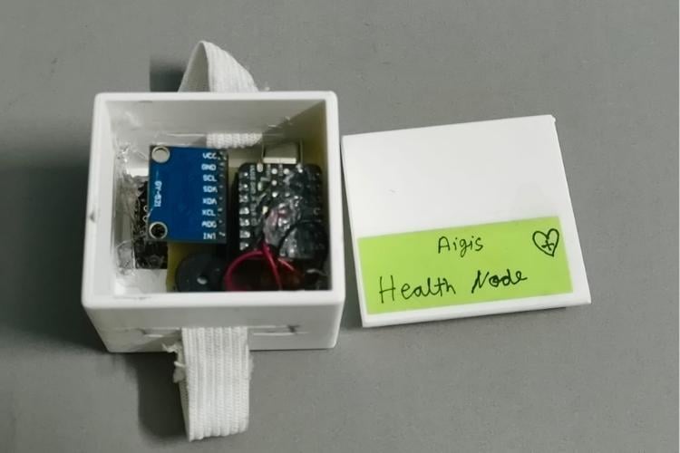
C) The Health Node (The Shield)
The Health Node is a wrist-worn wearable that uses accelerometer and heart rate sensor to monitor the user’s safety and vitals in real-time.
1. 3D Printing & Mechanical Preparation
Because this node is wearable, the enclosure focuses on ergonomics and a small footprint.
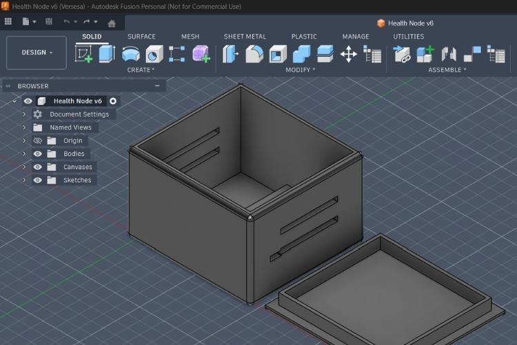
- Wristband Chassis: A two-part snap-fit enclosure with slots for a standard 20mm watch strap or elastic bands
- Sensor Window: The bottom plate features a precision cutout for the MAX30102 sensor to ensure direct contact with the skin for accurate heart rate and SpO_2 readings.
- Print Settings:
- Material: PLA is best for the main housing.
- Infill: 15% (to keep the device lightweight).
- Layer Height: 0.1mm for a smooth, comfortable finish against the skin.
I have attached the STL file of this design as the name as Health_Node_Aigis_3D file.
2. PCB & Circuitry (Compact Integration)
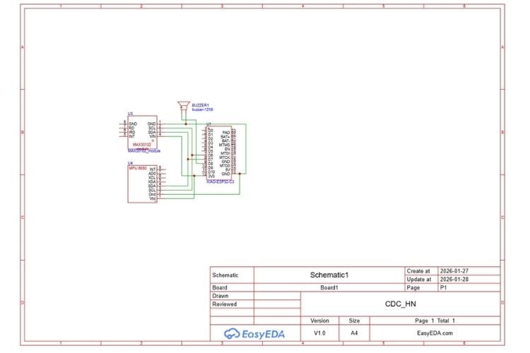
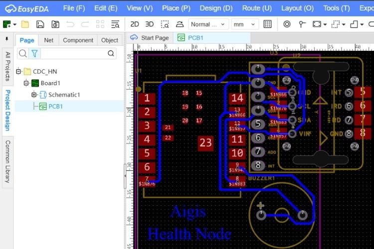
Due to the tiny size of the Seeed XIAO ESP32-C3, this node requires precise soldering.
- I2C Shared Bus: A custom mini-PCB or high-density wiring layout connects both the MPU6050 and MAX30102 to the XIAO’s I2C pins (D4/SDA, D5/SCL).
- Power Circuit: Includes a miniature slide switch and a JST connector for the 3.7V 135mAh LiPo battery.
- Alert System: A tiny 5V active piezo buzzer is integrated to provide immediate haptic/auditory feedback if the controller detects a fall.
You can use the Gerber file that i have attached as Health_Node_Aigis_PCB to manufacture this PCB
3. Hardware Assembly Steps
- Sensor Stack: Solder the MPU6050 and MAX30102 to the I2C bus, ensuring the MAX30102 is positioned at the bottom of the stack to face the skin.
- Controller Connection: Wire the sensor stack and the buzzer to the XIAO ESP32-C3. Keep wires as short as possible to fit the enclosure.
- Battery & Switch: Connect the LiPo battery through the slide switch. Tuck the battery behind the XIAO module
- Final Fitting: Place the assembly into the 3D-printed housing, ensuring the MAX30102 lens is clean and centered in its window. Snap the top cover in place.
4. Build Video Reference
Check this video i have given all steps in very detail you just need to follow it up.
Health Node Assembly video tutorial link: https://www.youtube.com/watch?v=sPTYYVidauc
5. Final look of Health Node:
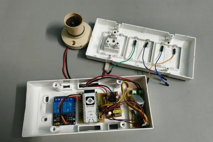
D) The Smart Home Node (The Hands)
The Smart Home Node is the executive arm of the Aigis ecosystem, managing high-power appliances with a focus on seamless manual and AI integration.
1. 3D Printing & Mechanical Preparation
Safety is the priority here, as the enclosure must house high-voltage AC components.
- Junction Box Enclosure: A custom-designed, flame-retardant enclosure that fits into a standard wall switchboard or acts as a standalone hub.
- Touch Pad Mounts: The front panel includes four recessed slots for copper/aluminum foil pads that act as the capacitive touch interfaces.
- This box is quite popular and easily available in electric shop , i have also put the purchase link in components section.
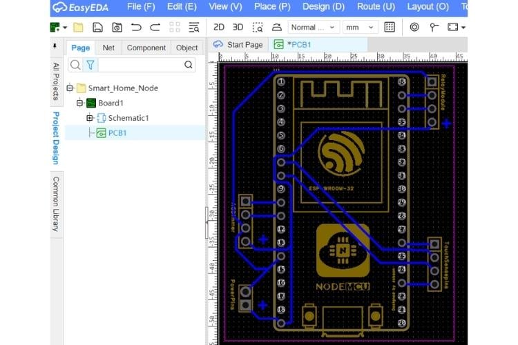
2. PCB & Circuitry (AC/DC Hybrid & XOR Logic)
This circuit is built to handle the interplay between 220V AC and 5V DC logic.
- Integrated AC-DC Power: The NodeMCU ESP32 S is powered by a built-in HLK-PM01 (or similar) buck converter module to draw power directly from the mains.
- The XOR Logic System: The firmware implements an XOR (Exclusive OR) logic gate between the Physical Touch State and the Software Command State. This ensures that the relay toggles its current state regardless of whether the command came from a finger touch or an ESP-NOW message from Aigis.
- Safety Isolation: Optical isolation is used within the relay and ACdimmer modules to keep the high-voltage spikes away from the ESP32 pins
You can use the Gerber file that i have attached as Smart_Home_Node_Aigis_PCB to manufacture this PCB
3. Hardware Assembly Steps
- AC-DC Integration: Solder the AC mains input to the buck converter and wire the 5V output to the NodeMCU's VIN and GND pins.
- Relay & Dimmer Wiring: Connect the relay inputs to the ESP32. Wire the AC "Live" wire through the relay common (COM) and normally open (NO) terminals to the light and socket.
- Touch Plate Setup: Adhere four metal foil pads to the inside of the 3D-printed front panel. Connect these to the ESP32’s touch-capable pins (GPIO 4, 32, 33, 15) using short, shielded wires.
- Final Installation: Secure the components inside the enclosure using nylon standoffs. Double-check all AC connections for insulation before snapping the touch panel into place.
4. Build Video Reference
Smart Home Node Assembly video tutorial link: https://www.youtube.com/watch?v=9zycPttw5mY
5. Final look of Smart home Node:
Here finishes the hardware part and again i recommend you also to put your creativity on the base designs use free tools for designing your versions as well. all design files are there in git folder each node have folder for PCB and 3D case designs .
Code Explanation
V. Software and Code Configuration
The Aigis ecosystem operates on a distributed intelligence model. Instead of a single monolithic script, each node runs specialized firmware optimized for its hardware. All nodes are interconnected using a Master-Slave Star Topology via the ultra-low-latency ESP-NOW protocol.
A) Aigis Master (Brain & Body)
Aigis is an advanced AI-powered family guardian and smart home companion built on the ESP32-S3 Box 3 platform. It combines offline speech recognition, multimedia capabilities, and wireless mesh networking to create a central hub for home automation and health monitoring.
Key Features:
- Offline Speech Recognition: Supports custom voice commands for privacy and reliability, without needing an internet connection.
- Multimedia Experience: Features a rich UI on the LCD screen, audio feedback, and music playback.
- Wireless Mesh Network: Acts as the central node in an ESP-NOW mesh network, communicating with:
- Door Node (ESP32-CAM): For visitor detection and door lock control.
- Health Node (Xiao C3): For monitoring fall detection and vitals (Heart Rate/SpO2).
- Smart Home Node (NodeMCU 32 ): For controlling smart home appliances (Lights, Fans, Sockets).
- Safety & Security: Integrates fall detection alarms and door security features.
System Architecture
The project follows a modular architecture, separating hardware drivers, middleware, and application logic.
Directory Structure
- main/: Core application source code.
- main.c: Application entry point and initialization.
- app/: Functional modules (SR, Audio, ESP-NOW, LED, UART).
- gui/: Graphical User Interface (generated by SquareLine Studio or custom LVGL code).
- *_ui.c: Specific UI logic for different modes (Door, Dance, Story, Fall).
- spiffs/: File system resources (Audio files, images).
Functional Modules
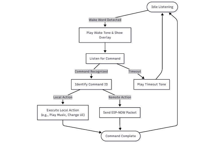
A. Speech Recognition (SR)
- Module: app/app_sr.c, app/app_sr_handler.c
- Functionality:
- Wake Word Detection: Listens for "Hi ESP" or "Hi Lexin".
- Command Recognition: Once woken, it listens for specific commands defined inapp_sr.h (e.g., "Turn on light one", "Lock the door", "Help me").
- Command Handling: Recognized commands are sent to a queue and processed by sr_handler_task.
- Feedback:
- Plays distinct audio tones for Wake, Command Recognized, and Timeout.
- Updates the UI overlay to show recognized text.
B. Wireless Communication (ESP-NOW)
- Module: app/app_espnow.c
- Protocol: ESP-NOW (Connectionless, low-latency, peer-to-peer).
- Roles:
- Sender: Sends commands to Control Node (Lights/Fan) and Door Node (Lock/Unlock).
- Receiver: Receives status updates from Health Node (Fall Detected, Vitals) and Door Node (Visitor Name).
- Data Structures:
- control_node_data_t: Simple integer commands.
- health_node_data_t: Boolean flags for fall/alarm and float/int for vitals.
- door_node_data_recv_t: String receiving the name of the recognized person.
C. Audio System
- Module: app/app_audio.c
- Driver: Uses I2S interface to drive the onboard codec/amplifier.
- Feature: Wraps esp-audio-player to play MP3 files stored in SPIFFS.
- Use Cases: Background music for "Dance Mode", storytelling for "Story Mode", and alarm sirens for "Fall Detection".
D. User Interface (UI)
- Framework: LVGL (Light Versatile Graphics Library).
- Modes:
- Main UI: The idle face of Aigis.
- Door UI: Shows the recognized visitor's name and status (Locked/Unlocked).
- Dance UI: distinctive animation for the dance feature.
- Story UI: Visuals accompanying the storytelling feature.
- Fall UI: Critical red alert screen when a fall is detected.
E. Fall Monitor
- Module: app_fall_monitor.c
Workflow:
- Health Node detects a fall and sends an ESP-NOW packet.
- app_espnow receives the packet and passes it to app_fall_monitor.
- Monitor triggers the Fall UI (Visual Alert) and plays a Siren (Audio Alert).
- Alarm persists until manually reset via voice command ("Stop").
These all files are there in github repository kindly check and explore. also check there read me file that will guide you
Application Flowcharts
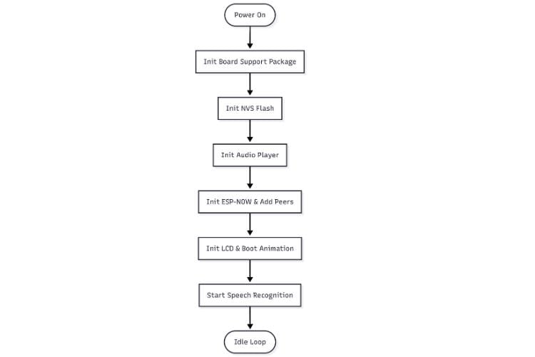
System Initialization Flow
Voice Command Processing Flow
Use full links that helped to make the
B) Door Node (The Eyes) - Firmware Logic
The Door Node firmware turns the ESP32-CAM into an intelligent, autonomous security guard. Its logic is designed for efficiency, remaining in a passive state until triggered by real-world events. The system integrates a PIR motion sensor for wake-up, an Edge Impulse TinyML model for on-device face recognition, and ESP-NOW for instant two-way communication with the Aigis Master.
To make firmware i have used arduino IDE with esp32 board version 3.1.7, also used edge Impulse plat form to make tiny ML model link below is reference project it will guide you how to make tiny ML and add the exported library to arduino IDE. this step is first then use below logic and code to make it for door node.
Reference project link to make Tiny ML model with edge impulse this project is tutorial by circuit digest platform
Screen shot of me making tiny Ml model.


Results :
model is not much mature as it got less data base but i will make sure to mature it well in future with more datasets.
Firmware Logic Flowchart
The following flowchart illustrates the exact decision-making process programmed into the ESP32-CAM.
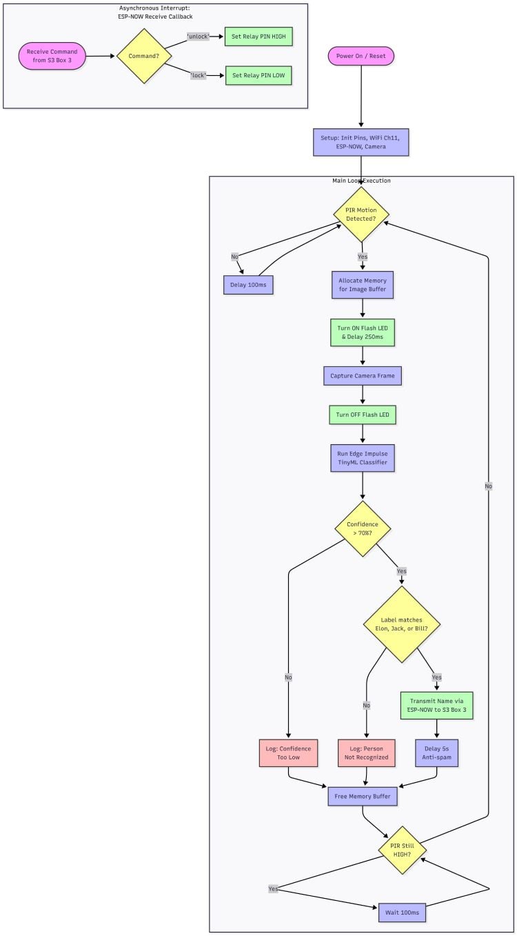
Detailed Logic Explanation:
Based on the flowchart above, the code's logic is divided into a main execution loop and an asynchronous interrupt for handling incoming commands.
1. Main Loop: Motion-Triggered Recognition
- Motion Detection (PIR): The node's primary state is a low-power loop that constantly polls the passive infrared (PIR) sensor. The main sequence is only triggered when motion is detected.
- Image Acquisition: Once triggered, the system allocates memory for a frame buffer, activates the on-board flash LED for illumination, captures a single camera frame, and then immediately deactivates the flash to conserve power.
- Edge AI Inference: The captured image is passed to a local Edge Impulse TinyML classifier. This lightweight neural network analyzes the image on the device itself to detect and identify faces.
- Authentication & Alerting:
- The code first checks if the AI model's confidence score is above a predefined threshold (e.g., 85%).
- If the score is high enough, it checks if the recognized face matches one of the authorized users (e.g., "Elon," "Jack," or "Bill").
- If a match is found, the user's name is packaged into a message and transmitted to the Aigis Master unit via ESP-NOW. An anti-spam delay ensures the master is not flooded with repeated alerts for the same event.
- Memory Management: Regardless of the recognition outcome, the image buffer is freed at the end of each cycle to prevent memory leaks, and the system returns to polling the PIR sensor.
2. Asynchronous Command Handling (ESP-NOW)
Receive Callback: Independently of the main loop, the firmware registers an ESP-NOW receive callback function. This function acts as an interrupt that triggers whenever a message arrives from the Aigis Master.
Action Execution: The callback analyzes the incoming command string.
If the command is 'unlock', it immediately sets the relay control pin to HIGH, activating the solenoid lock to open the door.
If the command is 'lock', it sets the pin to LOW, securing the door.
Door Node Source Code
Below is the complete Arduino sketch that implements the vision, AI, and communication logic shown in the flowchart.
/* Includes ---------------------------------------------------------------- */
#include <Aigis_Door_Node_inferencing.h>
#include "edge-impulse-sdk/dsp/image/image.hpp"
#include "esp_camera.h"
// --- Networking & ESP-NOW ---
#include <WiFi.h>
#include <esp_now.h>
#include <esp_wifi.h>
//#define CAMERA_MODEL_ESP_EYE // Has PSRAM
#define CAMERA_MODEL_AI_THINKER // Has PSRAM
#if defined(CAMERA_MODEL_ESP_EYE)
#define PWDN_GPIO_NUM    -1
#define RESET_GPIO_NUM   -1
#define XCLK_GPIO_NUM    4
#define SIOD_GPIO_NUM    18
#define SIOC_GPIO_NUM    23
#define Y9_GPIO_NUM      36
#define Y8_GPIO_NUM      37
#define Y7_GPIO_NUM      38
#define Y6_GPIO_NUM      39
#define Y5_GPIO_NUM      35
#define Y4_GPIO_NUM      14
#define Y3_GPIO_NUM      13
#define Y2_GPIO_NUM      34
#define VSYNC_GPIO_NUM   5
#define HREF_GPIO_NUM    27
#define PCLK_GPIO_NUM    25
#elif defined(CAMERA_MODEL_AI_THINKER)
#define PWDN_GPIO_NUM     32
#define RESET_GPIO_NUM    -1
#define XCLK_GPIO_NUM      0
#define SIOD_GPIO_NUM     26
#define SIOC_GPIO_NUM     27
#define Y9_GPIO_NUM       35
#define Y8_GPIO_NUM       34
#define Y7_GPIO_NUM       39
#define Y6_GPIO_NUM       36
#define Y5_GPIO_NUM       21
#define Y4_GPIO_NUM       19
#define Y3_GPIO_NUM       18
#define Y2_GPIO_NUM        5
#define VSYNC_GPIO_NUM    25
#define HREF_GPIO_NUM     23
#define PCLK_GPIO_NUM     22
#else
#error "Camera model not selected"
#endif
/* Constant defines -------------------------------------------------------- */
#define EI_CAMERA_RAW_FRAME_BUFFER_COLS           320
#define EI_CAMERA_RAW_FRAME_BUFFER_ROWS           240
#define EI_CAMERA_FRAME_BYTE_SIZE                 3
// --- Hardware & Logic Defines ---
// HARDWARE FIX: Changed pins to avoid PSRAM and Bootstrapper conflicts
#define PIR_PIN 13                 // PIR sensor input
#define RELAY_PIN 14               // Relay control (LOW = Lock, HIGH = Unlock)
#define FLASH_LED_PIN 4            // Onboard High-Power Flash LED
#define CONFIDENCE_THRESHOLD 0.60  // 70% confidence required to trigger
// --- ESP-NOW Configuration ---
// MAC ADDRESS OF ESP32-S3-BOX-3
uint8_t box3MacAddress[] = {0xB4, 0x3A, 0x45, 0xF3, 0x9E, 0x50};
// Structure to SEND data (Recognized Name)
typedef struct struct_message_send {
   char name[32];
} struct_message_send;
// Structure to RECEIVE data (Door Command)
typedef struct struct_message_recv {
   char command[16];
} struct_message_recv;
struct_message_send sendData;
struct_message_recv recvData;
esp_now_peer_info_t peerInfo;
/* Private variables ------------------------------------------------------- */
static bool debug_nn = false;
static bool is_initialised = false;
uint8_t *snapshot_buf;
static camera_config_t camera_config = {
   .pin_pwdn = PWDN_GPIO_NUM,
   .pin_reset = RESET_GPIO_NUM,
   .pin_xclk = XCLK_GPIO_NUM,
   .pin_sscb_sda = SIOD_GPIO_NUM,
   .pin_sscb_scl = SIOC_GPIO_NUM,
   .pin_d7 = Y9_GPIO_NUM,
   .pin_d6 = Y8_GPIO_NUM,
   .pin_d5 = Y7_GPIO_NUM,
   .pin_d4 = Y6_GPIO_NUM,
   .pin_d3 = Y5_GPIO_NUM,
   .pin_d2 = Y4_GPIO_NUM,
   .pin_d1 = Y3_GPIO_NUM,
   .pin_d0 = Y2_GPIO_NUM,
   .pin_vsync = VSYNC_GPIO_NUM,
   .pin_href = HREF_GPIO_NUM,
   .pin_pclk = PCLK_GPIO_NUM,
   .xclk_freq_hz = 20000000,
   .ledc_timer = LEDC_TIMER_0,
   .ledc_channel = LEDC_CHANNEL_0,
   .pixel_format = PIXFORMAT_JPEG,
   .frame_size = FRAMESIZE_QVGA,
   .jpeg_quality = 12,
   .fb_count = 1,
   .fb_location = CAMERA_FB_IN_PSRAM,
   .grab_mode = CAMERA_GRAB_WHEN_EMPTY,
};
/* Function definitions ------------------------------------------------------- */
bool ei_camera_init(void);
void ei_camera_deinit(void);
bool ei_camera_capture(uint32_t img_width, uint32_t img_height, uint8_t *out_buf);
static int ei_camera_get_data(size_t offset, size_t length, float *out_ptr);
// --- ESP-NOW Callbacks ---
void OnDataSent(const uint8_t *mac_addr, esp_now_send_status_t status) {
   Serial.print("Data Delivery Status: ");
   Serial.println(status == ESP_NOW_SEND_SUCCESS ? "Success" : "Failed");
}
void OnDataRecv(const esp_now_recv_info_t * esp_now_info, const uint8_t *incomingData, int len) {
   int copyLen = len;
   if (copyLen > sizeof(recvData)) {
       copyLen = sizeof(recvData);
   }

   memset(&recvData, 0, sizeof(recvData));
   memcpy(&recvData, incomingData, copyLen);
   Serial.printf("\n[Command Received]: %s\n", recvData.command);
   if (strcmp(recvData.command, "unlock") == 0) {
       digitalWrite(RELAY_PIN, HIGH);
       Serial.println("Action: Door Unlocked!");
   }
   else if (strcmp(recvData.command, "lock") == 0) {
       digitalWrite(RELAY_PIN, LOW);
       Serial.println("Action: Door Locked!");
   }
}
/**
* @brief      Arduino setup function
*/
void setup()
{
   Serial.begin(115200);
   while (!Serial);
   Serial.println("Starting Node Initialization...");
   // Initialize Hardware Pins
   pinMode(PIR_PIN, INPUT_PULLDOWN);
   pinMode(RELAY_PIN, OUTPUT);
   pinMode(FLASH_LED_PIN, OUTPUT);
   digitalWrite(RELAY_PIN, LOW);
   digitalWrite(FLASH_LED_PIN, LOW); // Ensure flash is off at boot
   // Cleanly initialize Wi-Fi to Channel 11
   WiFi.mode(WIFI_STA);
   WiFi.setSleep(false); // Prevents ESP-NOW packets dropping
   esp_wifi_start();
   esp_wifi_set_channel(11, WIFI_SECOND_CHAN_NONE);
   // Initialize ESP-NOW
   if (esp_now_init() != ESP_OK) {
       Serial.println("Critical Error: Failed to initialize ESP-NOW");
       return;
   }
   // Register Callbacks
   esp_now_register_send_cb(OnDataSent);
   esp_now_register_recv_cb(OnDataRecv);
   // Register S3 Box 3 as a Peer
   memset(&peerInfo, 0, sizeof(peerInfo));
   memcpy(peerInfo.peer_addr, box3MacAddress, 6);
   peerInfo.channel = 11;
   peerInfo.encrypt = false;
   peerInfo.ifidx = WIFI_IF_STA;
   if (esp_now_add_peer(&peerInfo) != ESP_OK){
       Serial.println("Failed to add S3 Box 3 as peer");
       return;
   }
   if (ei_camera_init() == false) {
       ei_printf("Failed to initialize Camera!\r\n");
   } else {
       ei_printf("Camera initialized successfully.\r\n");
   }
   ei_printf("\nSystem Ready. Waiting for motion on PIR sensor...\n");
}
/**
* @brief      Main Loop - Awaits PIR trigger, runs inference, and transmits matches
*/
void loop()
{
   if (digitalRead(PIR_PIN) == HIGH) {
       Serial.println("\nMotion Detected! Capturing frame...");
       snapshot_buf = (uint8_t*)malloc(EI_CAMERA_RAW_FRAME_BUFFER_COLS * EI_CAMERA_RAW_FRAME_BUFFER_ROWS * EI_CAMERA_FRAME_BYTE_SIZE);
       if(snapshot_buf == nullptr) {
           ei_printf("ERR: Failed to allocate snapshot buffer!\n");
           return;
       }
       ei::signal_t signal;
       signal.total_length = EI_CLASSIFIER_INPUT_WIDTH * EI_CLASSIFIER_INPUT_HEIGHT;
       signal.get_data = &ei_camera_get_data;
       // Turn on the Flash LED and wait slightly for auto-exposure to adjust
       digitalWrite(FLASH_LED_PIN, HIGH);
       delay(250);
       if (ei_camera_capture((size_t)EI_CLASSIFIER_INPUT_WIDTH, (size_t)EI_CLASSIFIER_INPUT_HEIGHT, snapshot_buf) == false) {
           ei_printf("Failed to capture image\r\n");
           digitalWrite(FLASH_LED_PIN, LOW); // Turn off if capture fails
           free(snapshot_buf);
           return;
       }
       // Immediately turn off the Flash LED after the capture
       digitalWrite(FLASH_LED_PIN, LOW);
       ei_impulse_result_t result = { 0 };
       EI_IMPULSE_ERROR err = run_classifier(&signal, &result, debug_nn);
       if (err != EI_IMPULSE_OK) {
           ei_printf("ERR: Failed to run classifier (%d)\n", err);
           free(snapshot_buf);
           return;
       }
       char best_label[32] = "unknown";
       float best_value = 0.0;
#if EI_CLASSIFIER_OBJECT_DETECTION == 1
       for (uint32_t i = 0; i < result.bounding_boxes_count; i++) {
           ei_impulse_result_bounding_box_t bb = result.bounding_boxes[i];
           if (bb.value > best_value) {
               best_value = bb.value;
               strcpy(best_label, bb.label);
           }
       }
#else
       for (uint16_t i = 0; i < EI_CLASSIFIER_LABEL_COUNT; i++) {
           if (result.classification[i].value > best_value) {
               best_value = result.classification[i].value;
               strcpy(best_label, ei_classifier_inferencing_categories[i]);
           }
       }
#endif
       ei_printf("Top Prediction: %s (Confidence: %.2f)\n", best_label, best_value);
       if (best_value > CONFIDENCE_THRESHOLD) {
           if (strcmp(best_label, "Elon") == 0 ||
               strcmp(best_label, "Jack") == 0 ||
               strcmp(best_label, "Bill") == 0) {

               Serial.printf("Authorized Person Identified: %s. Sending to S3 Box 3...\n", best_label);

               strcpy(sendData.name, best_label);
               esp_now_send(box3MacAddress, (uint8_t *) &sendData, sizeof(sendData));

               delay(5000);
           } else {
               Serial.println("Person not recognized as authorized.");
               delay(2000);
           }
       } else {
           Serial.println("Confidence too low. Ignoring.");
           delay(1000);
       }
       free(snapshot_buf);

       while(digitalRead(PIR_PIN) == HIGH) {
           delay(100);
       }
       Serial.println("Motion cleared. Returning to standby.");
   }
   else {
       delay(100);
   }
}
// =========================================================================
// Below are the unchanged helper functions provided from the original code
// =========================================================================
bool ei_camera_init(void) {
   if (is_initialised) return true;
#if defined(CAMERA_MODEL_ESP_EYE)
 pinMode(13, INPUT_PULLUP);
 pinMode(14, INPUT_PULLUP);
#endif
   esp_err_t err = esp_camera_init(&camera_config);
   if (err != ESP_OK) {
     Serial.printf("Camera init failed with error 0x%x\n", err);
     return false;
   }
   sensor_t * s = esp_camera_sensor_get();
   if (s->id.PID == OV3660_PID) {
     s->set_vflip(s, 1);
     s->set_brightness(s, 1);
     s->set_saturation(s, 0);
   }
#if defined(CAMERA_MODEL_M5STACK_WIDE)
   s->set_vflip(s, 1);
   s->set_hmirror(s, 1);
#elif defined(CAMERA_MODEL_ESP_EYE)
   s->set_vflip(s, 1);
   s->set_hmirror(s, 1);
   s->set_awb_gain(s, 1);
#endif
   is_initialised = true;
   return true;
}
void ei_camera_deinit(void) {
   esp_err_t err = esp_camera_deinit();
   if (err != ESP_OK) {
       ei_printf("Camera deinit failed\n");
       return;
   }
   is_initialised = false;
   return;
}
bool ei_camera_capture(uint32_t img_width, uint32_t img_height, uint8_t *out_buf) {
   bool do_resize = false;
   if (!is_initialised) {
       ei_printf("ERR: Camera is not initialized\r\n");
       return false;
   }
   camera_fb_t *fb = esp_camera_fb_get();
   if (!fb) {
       ei_printf("Camera capture failed\n");
       return false;
   }
  bool converted = fmt2rgb888(fb->buf, fb->len, PIXFORMAT_JPEG, snapshot_buf);
  esp_camera_fb_return(fb);
  if(!converted){
      ei_printf("Conversion failed\n");
      return false;
  }
   if ((img_width != EI_CAMERA_RAW_FRAME_BUFFER_COLS)
       || (img_height != EI_CAMERA_RAW_FRAME_BUFFER_ROWS)) {
       do_resize = true;
   }
   if (do_resize) {
       ei::image::processing::crop_and_interpolate_rgb888(
       out_buf,
       EI_CAMERA_RAW_FRAME_BUFFER_COLS,
       EI_CAMERA_RAW_FRAME_BUFFER_ROWS,
       out_buf,
       img_width,
       img_height);
   }
   return true;
}
static int ei_camera_get_data(size_t offset, size_t length, float *out_ptr)
{
   size_t pixel_ix = offset * 3;
   size_t pixels_left = length;
   size_t out_ptr_ix = 0;
   while (pixels_left != 0) {
       out_ptr[out_ptr_ix] = (snapshot_buf[pixel_ix + 2] << 16) + (snapshot_buf[pixel_ix + 1] << 8) + snapshot_buf[pixel_ix];
       out_ptr_ix++;
       pixel_ix+=3;
       pixels_left--;
   }
   return 0;
}
C) Health Node (The Shield) - Firmware Logic
Unlike the vision-based Door Node, the Health Node does not rely on complex neural networks. Instead, it uses a highly optimized, low-latency threshold-based algorithm derived from physics principles to detect falls.
The firmware continuously polls the MPU6050 IMU via I2C and analyzes the acceleration vectors in real-time. The detection logic rests on the principle that a typical fall event follows a specific pattern: a brief moment of "weightlessness" (freefall) followed immediately by a high-G impact.
For health node you also need to set up circuit digest cloud SMS API for this i have used circuit digest cloud tutorial look into the below reference tutorial its very easy and steps are shown in simple manner have a look this step is first to make health node code .
Reference tutorial link to integrate with circuit digest cloud for SMS alerts .
Firmware Logic Flowchart
The following flowchart illustrates the exact decision-making process programmed into the Seed XIAO ESP32-C3.
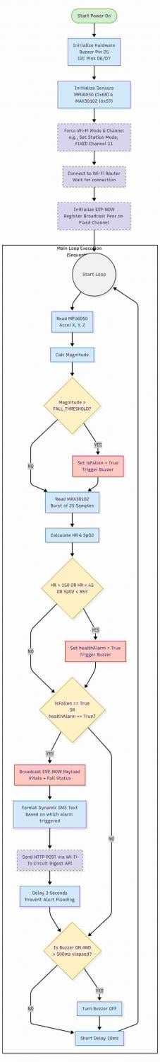
Detailed Logic Explanation:
Based on the flowchart above, the code executes the following steps in its main loop:
1. Initialization & Calibration: Upon boot, the system initializes the I2C bus, connects to the MPU6050, and performs a calibration routine to determine sensor offsets (indicated by blinking LEDs), ensuring accurate readings.
2. Vector Magnitude Calculation: The code reads raw acceleration data from all three axes (a_x, a_y, a_z). It then calculates the total Magnitude Vector Sum using the formula: sqrt{a_x^2 + a_y^2 + a_z^2}. This gives a single value representing the total force acting on the device.
3. Stage 1: Freefall Detection: The code checks if the generated Magnitude is below a specific Low Threshold (e.g., < 0.5g). If true, it indicates the user is in freefall. A fallDetected flag is set to TRUE, and a timer begins.
4. Stage 2: Impact Confirmation: Immediately after, the code checks if the Magnitude exceeds a High Threshold (e.g., > 3.0g). If this high G-force occurs while the fallDetected flag is already TRUE (meaning freefall just happened), a fall is confirmed.
5. Rotation Check (Secondary Confirmation): As shown in the flowchart, the code also monitors gyroscope data. A rapid change in rotation ($g_z > 200 deg/sec$) acts as a secondary confirmation of a violent movement pattern.
6. Alert Triggering: Upon confirming the fall pattern (Stage 1 + Stage 2), the firmware activates the local Piezo Buzzer for immediate audio feedback and simultaneously broadcasts a critical "FALL DETECTED" packet to the Aigis Master via ESP-NOW.
Health Node Source Code
Below is the complete Arduino sketch implementing the flowchart logic shown above.
#include <Wire.h>
#include <Adafruit_MPU6050.h>
#include <Adafruit_Sensor.h>
#include <WiFi.h>
#include <esp_now.h>
#include "MAX30105.h"
#include "spo2_algorithm.h"
// --- PIN DEFINITIONS FOR XIAO ESP32-C3 ---
#define I2C_SDA_PIN D7 // GPIO 20
#define I2C_SCL_PIN D6 // GPIO 21
#define BUZZER_PIN  D5 // GPIO 8
// --- I2C ADDRESSES ---
#define MPU_ADDR 0x68
#define MAX_ADDR 0x57
// --- WIFI & SMS CONFIGURATION ---
const char* ssid = "xxxxx";           // Replace with your Wi-Fi Name
const char* password = "xxxxxxxx";   // Replace with your Wi-Fi Password
// Circuit Digest API Details
const char* apiKey = "xxxzxxxxx";           // Replace with your API key
const char* templateID = "101";                // Using Template 101: "Your {#var#} is currently at {#var#}."
const char* mobileNumber = "xxxxxxxxxx";     // Replace with recipient number (include Country Code!)
const char* var1 = "HEALTH BAND";              // Custom variable 1
const char* var2 = "FALL DETECTED";            // Custom variable 2
// --- CONFIGURATION ---
const float FALL_THRESHOLD = 25.0;
const int HR_HIGH_LIMIT = 150;
const int HR_LOW_LIMIT = 45;
const int SPO2_LOW_LIMIT = 85;
// --- OBJECTS ---
Adafruit_MPU6050 mpu;
MAX30105 particleSensor;
// --- ESP-NOW VARIABLES ---
uint8_t broadcastAddress[] = {0xB4, 0x3A, 0x45, 0xF3, 0x9E, 0x50}; // b4:3a:45:f3:9e:50
typedef struct struct_message {
 bool fallDetected;
 bool healthAlarm;
 float heartRate;
 int spo2;
} struct_message;
struct_message myData;
esp_now_peer_info_t peerInfo;
// --- HEALTH VARIABLES ---
uint32_t irBuffer[100];
uint32_t redBuffer[100];
int32_t bufferLength = 100;
int32_t spo2;
int8_t validSPO2;
int32_t heartRate;
int8_t validHeartRate;
// Buzzer timing
unsigned long buzzerStartTime = 0;
bool isBuzzing = false;
// Function declarations
void sendSMS();
void triggerAlarm();
void handleBuzzer();
void setup() {
 Serial.begin(115200);

 // 1. Init Buzzer
 pinMode(BUZZER_PIN, OUTPUT);
 digitalWrite(BUZZER_PIN, LOW);
 // 2. Init I2C
 Wire.begin(I2C_SDA_PIN, I2C_SCL_PIN);
 // 3. Init MPU6050
 if (!mpu.begin(MPU_ADDR, &Wire)) {
   Serial.println("Failed to find MPU6050 chip at 0x68!");
   while (1) { delay(10); }
 }
 Serial.println("MPU6050 Found at 0x68!");

 mpu.setAccelerometerRange(MPU6050_RANGE_8_G);
 mpu.setGyroRange(MPU6050_RANGE_500_DEG);
 mpu.setFilterBandwidth(MPU6050_BAND_21_HZ);
 // 4. Init MAX30102 (Logic commented out in loop)
 if (!particleSensor.begin(Wire, 400000, MAX_ADDR)) {
   Serial.println("MAX30102 not found. (Ignored for Fall Test)");
 } else {
   Serial.println("MAX30102 Found!");
   byte ledBrightness = 60;
   byte sampleAverage = 4;
   byte ledMode = 2;
   byte sampleRate = 100;
   int pulseWidth = 411;
   int adcRange = 4096;
   particleSensor.setup(ledBrightness, sampleAverage, ledMode, sampleRate, pulseWidth, adcRange);
 }
 // 5. Connect to Wi-Fi FIRST (Crucial for combined ESP-NOW & Wi-Fi)
 WiFi.mode(WIFI_STA);
 Serial.print("Connecting to Wi-Fi...");
 WiFi.begin(ssid, password);
 while (WiFi.status() != WL_CONNECTED) {
   delay(500);
   Serial.print(".");
 }
 Serial.println("\nWi-Fi connected!");
 Serial.print("Operating on Wi-Fi Channel: ");
 Serial.println(WiFi.channel()); // Take note of this channel for your Receiver!
 // 6. Init ESP-NOW (It will inherit the Wi-Fi router's channel)
 if (esp_now_init() != ESP_OK) {
   Serial.println("Error initializing ESP-NOW");
   return;
 }

 memcpy(peerInfo.peer_addr, broadcastAddress, 6);
 peerInfo.channel = 0;  // 0 means it uses the current active channel (the router's channel)
 peerInfo.encrypt = false;

 if (esp_now_add_peer(&peerInfo) != ESP_OK){
   Serial.println("Failed to add peer");
   return;
 }
}
void loop() {
 // --- FALL DETECTION ---
 sensors_event_t a, g, temp;
 mpu.getEvent(&a, &g, &temp);
 float accel_magnitude = sqrt(pow(a.acceleration.x, 2) + pow(a.acceleration.y, 2) + pow(a.acceleration.z, 2));

 bool isFallen = false;
 if (accel_magnitude > FALL_THRESHOLD) {
   isFallen = true;
   Serial.println("!!! FALL DETECTED !!!");
   triggerAlarm();
 }
 // --- HEALTH MONITORING (COMMENTED OUT FOR TESTING) ---
 /*
 // [Health code is temporarily bypassed for testing fall detection]
 */
 // --- DATA TRANSMISSION (ESP-NOW + SMS) ---
 if (isFallen) {
   // 1. Send ESP-NOW Message
   myData.fallDetected = isFallen;
   myData.healthAlarm = false;
   myData.heartRate = 0.0;
   myData.spo2 = 0;
   esp_err_t result = esp_now_send(broadcastAddress, (uint8_t *) &myData, sizeof(myData));
   if (result == ESP_OK) {
     Serial.println("ESP-NOW: Fall Alert Broadcasted!");
   } else {
     Serial.println("ESP-NOW: Error sending data");
   }
   // 2. Send SMS Alert via HTTP POST
   Serial.println("Triggering SMS Alert...");
   sendSMS();

   // Delay to stop flooding. Fall alerts shouldn't trigger multiple times a second.
   delay(3000);
 }

 handleBuzzer();
 delay(10);
}
// --- SMS SENDING FUNCTION ---
void sendSMS() {
 if (WiFi.status() == WL_CONNECTED) {
   WiFiClient client;
   String apiUrl = "/api/v1/send_sms?ID=" + String(templateID);

   Serial.print("Connecting to SMS server...");
   if (client.connect("www.circuitdigest.cloud", 80)) {
     Serial.println("connected!");

     // Create JSON payload
     String payload = "{\"mobiles\":\"" + String(mobileNumber) + "\",\"var1\":\"" + String(var1) + "\",\"var2\":\"" + String(var2) + "\"}";

     // Send HTTP POST request headers
     client.println("POST " + apiUrl + " HTTP/1.1");
     client.println("Host: www.circuitdigest.cloud");
     client.println("Authorization: " + String(apiKey));
     client.println("Content-Type: application/json");
     client.println("Content-Length: " + String(payload.length()));
     client.println(); // Empty line separates headers from payload

     // Send the JSON payload
     client.println(payload);

     // Wait briefly for response
     int timeout = millis();
     while (client.available() == 0) {
       if (millis() - timeout > 5000) {
         Serial.println(">>> Client Timeout!");
         client.stop();
         return;
       }
     }
     // Read HTTP response code to confirm success
     int responseCode = -1;
     while (client.available()) {
       String line = client.readStringUntil('\n');
       if (line.startsWith("HTTP/")) {
         responseCode = line.substring(9, 12).toInt();
         break; // We only care about the response code
       }
     }

     if (responseCode == 200) {
       Serial.println(">>> SMS SENT SUCCESSFULLY! <<<");
     } else {
       Serial.print(">>> Failed to send SMS. HTTP Code: ");
       Serial.println(responseCode);
     }

     client.stop();
   } else {
     Serial.println("Connection to SMS server failed!");
   }
 } else {
   Serial.println("Cannot send SMS: Wi-Fi disconnected!");
 }
}
void triggerAlarm() {
 digitalWrite(BUZZER_PIN, HIGH);
 buzzerStartTime = millis();
 isBuzzing = true;
}
void handleBuzzer() {
 if (isBuzzing) {
   if (millis() - buzzerStartTime > 500) {
     digitalWrite(BUZZER_PIN, LOW);
     isBuzzing = false;
   }
 }
}
D) Smart Home Node (The Hands) - Firmware Logic
The firmware for the NodeMCU ESP32-S is designed to provide "hybrid control," allowing high-voltage appliances to be operated seamlessly by both physical touch and remote AI commands without state conflicts. The logic is divided into three distinct, asynchronous processes: a main loop for touch polling, a hardware interrupt for AC dimming, and a wireless callback for remote control.
Firmware Logic Flowchart
The following flowchart illustrates the parallel processes running on the NodeMCU esp32 .
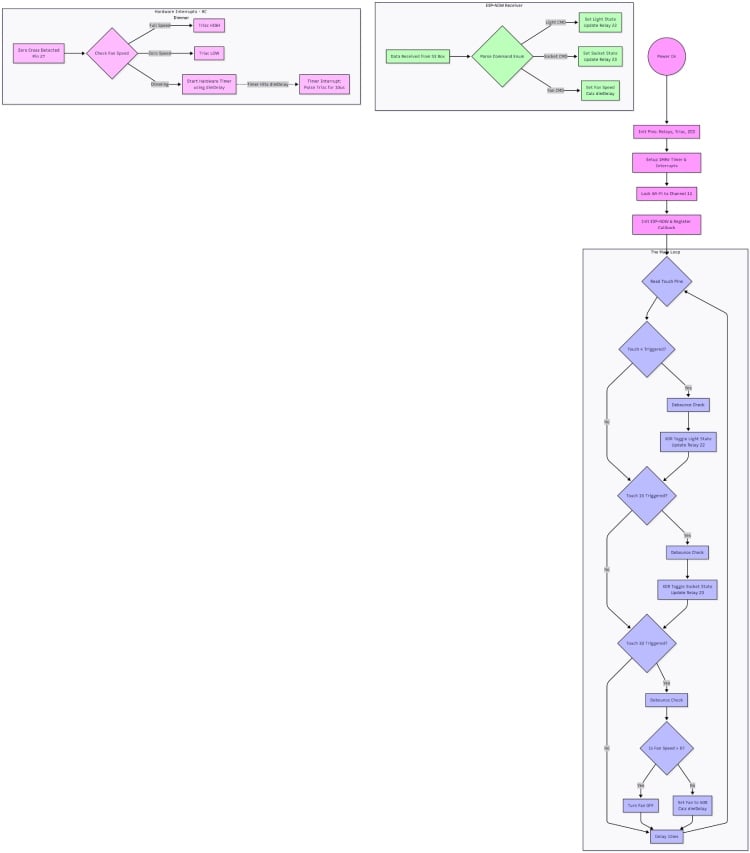
Detailed Logic Explanation:
Based on the flowchart above, the code executes these three parallel tasks:
- 1. Main Loop: Manual Touch Control (XOR Logic)
- The main loop continuously polls four capacitive touch pins (T1, T2, T3, T4).
- Relay Control (Touch 1 & 2): If Touch 1 (Light) or Touch 2 (Socket) is triggered, the code first applies a debounce check to prevent false triggers. It then uses XOR Logic to toggle the current status of the appliance (e.g., NewState = CurrentState ^ 1). Finally, it updates the physical relay pin (GPIO 22 or 21). This ensures physical touch always changes the state, regardless of previous remote commands.
- Fan Speed Control (Touch 3 & 4): If Touch 3 is triggered, fan speed increases by 10% (capped at 100%). If Touch 4 is triggered, speed decreases by 10% (floored at 0%).
- 2. Asynchronous Hardware Interrupt: AC Dimming (Zero-Crossing)
- This routine is triggered automatically by a hardware interrupt on Pin 27 every time the AC sine wave crosses zero volts (100 times per second for 50Hz AC).
- Speed Check: It checks the current target fan speed variable.
- 0% or 100%: The Triac is turned fully OFF or fully ON respectively, without delay.
- Dimming (1-99%): The code calculates a precise microsecond delay based on the desired speed. After waiting for this delay, it fires the Triac for a specific duration (e.g., 10µs) to "chop" the AC waveform, regulating power to the fan.
- 3. Asynchronous ESP-NOW Callback: Remote Control
- This function is triggered whenever a command packet arrives from the Aigis Master.
- It parses the incoming string (e.g., "Light ON", "Fan 60") and directly updates the same global state variables used by the main touch loop and the dimming interrupt, ensuring both manual and remote inputs stay synchronized.
Smart Home Node Source Code
Below is the complete Arduino sketch that implements the hybrid control, XOR logic, and zero-crossing dimming shown in the flowchart.
#include <esp_now.h>
#include <WiFi.h>
#include <esp_wifi.h> // <-- ADDED: Required to force the Wi-Fi Channel
// --- AIGIS SR COMMAND DEFINITIONS ---
typedef enum {
   TURN_ON_LIGHT_ONE = 1,
   TURN_OFF_LIGHT_ONE,
   TURN_ON_SOCKET,
   TURN_OFF_SOCKET,
   TURN_ON_FAN_AT_LEVEL_ONE,
   TURN_ON_FAN_AT_LEVEL_TWO,
   TURN_ON_FAN_AT_LEVEL_THREE,
   TURN_OFF_FAN
} aigis_command_t;
// ESP-NOW Data Structure
typedef struct struct_message {
 int command;
} struct_message;
struct_message myData;
// --- HARDWARE PIN DEFINITIONS ---
// Touch Pins
const int touchPinLight = 4;   // Touch for Relay 1 (Light)
const int touchPinSocket = 15; // Touch for Relay 2 (Socket)
const int touchPinFan = 33;    // Touch for Fan Dimmer
// Relay Pins
const int relayLightPin = 22;
const int relaySocketPin = 23;
// Fan Control Pins (Dimmer Circuit)
const int zcdPin = 27;    // Zero Crossing Detect (Input)
const int triacPin = 26;  // Triac Gate Control (Output)
// --- CONFIGURATION ---
const int threshold = 20;       // Touch sensitivity
const int debounceDelay = 300;  // 300ms debounce
// Dimmer Timings (for 50Hz AC)
const int minDelay = 1000; // High speed
const int maxDelay = 9000; // Low speed
// --- STATE VARIABLES ---
bool lightState = false;
bool socketState = false;
volatile int fanSpeed = 0; // 0-100%
volatile int dimDelay = 0; // Microseconds
unsigned long lastTouchTimeLight = 0;
unsigned long lastTouchTimeSocket = 0;
unsigned long lastTouchTimeFan = 0;
// --- HARDWARE TIMER ---
hw_timer_t *timer = NULL;
// --- INTERRUPT SERVICE ROUTINES (ISRs) ---
void IRAM_ATTR onTimer() {
 if (fanSpeed > 0) {
   digitalWrite(triacPin, HIGH);
   for(volatile int i=0; i<50; i++); // 10us trigger pulse
   digitalWrite(triacPin, LOW);
 }
}
void IRAM_ATTR onZeroCross() {
 if (fanSpeed >= 95) {
   digitalWrite(triacPin, HIGH);
 } else if (fanSpeed <= 0) {
   digitalWrite(triacPin, LOW);
 } else {
   timerWrite(timer, 0);
   timerAlarm(timer, dimDelay, false, 0); // V3.0 Timer Syntax
   digitalWrite(triacPin, LOW);
 }
}
// --- ESP-NOW CALLBACK (RECEIVING FROM AIGIS) ---
void OnDataRecv(const uint8_t * mac, const uint8_t *incomingData, int len) {
 memcpy(&myData, incomingData, sizeof(myData));
 Serial.print("Aigis Voice Command Received: ");
 Serial.println(myData.command);
 // LOGIC
 switch(myData.command) {
   // Light Control
   case TURN_ON_LIGHT_ONE:
     lightState = true;
     digitalWrite(relayLightPin, LOW);
     break;
   case TURN_OFF_LIGHT_ONE:
     lightState = false;
     digitalWrite(relayLightPin, HIGH);
     break;

   // Socket Control
   case TURN_ON_SOCKET:
     socketState = true;
     digitalWrite(relaySocketPin, LOW);
     break;
   case TURN_OFF_SOCKET:
     socketState = false;
     digitalWrite(relaySocketPin, HIGH);
     break;
   // Fan Control
   case TURN_ON_FAN_AT_LEVEL_ONE:
     fanSpeed = 33;
     dimDelay = map(fanSpeed, 1, 99, maxDelay, minDelay);
     break;
   case TURN_ON_FAN_AT_LEVEL_TWO:
     fanSpeed = 66;
     dimDelay = map(fanSpeed, 1, 99, maxDelay, minDelay);
     break;
   case TURN_ON_FAN_AT_LEVEL_THREE:
     fanSpeed = 100;
     dimDelay = map(fanSpeed, 1, 99, maxDelay, minDelay);
     break;
   case TURN_OFF_FAN:
     fanSpeed = 0;
     break;
 }
}
void setup() {
 Serial.begin(115200);
 // Setup Pins
 pinMode(relayLightPin, OUTPUT);
 pinMode(relaySocketPin, OUTPUT);
 pinMode(triacPin, OUTPUT);
 pinMode(zcdPin, INPUT_PULLUP);

 digitalWrite(relayLightPin, HIGH);
 digitalWrite(relaySocketPin, HIGH);
 digitalWrite(triacPin, LOW);
 // --- TIMER SETUP ---
 timer = timerBegin(1000000);
 timerAttachInterrupt(timer, &onTimer);
 attachInterrupt(digitalPinToInterrupt(zcdPin), onZeroCross, RISING);
 // --- WIFI / ESP-NOW ---
 WiFi.mode(WIFI_STA);

 // --- ADDED: FORCE WI-FI TO CHANNEL 11 ---
 esp_wifi_set_promiscuous(true);
 esp_wifi_set_channel(11, WIFI_SECOND_CHAN_NONE);
 esp_wifi_set_promiscuous(false);
 // ----------------------------------------
 if (esp_now_init() != ESP_OK) {
   Serial.println("ESP-NOW Init Failed");
   return;
 }
 esp_now_register_recv_cb(esp_now_recv_cb_t(OnDataRecv));
 Serial.println("Aigis Smart Node Ready on Channel 11.");
}
void loop() {
 // Read Touch Sensors
 int tLight = touchRead(touchPinLight);   // Pin 4
 int tSocket = touchRead(touchPinSocket); // Pin 15
 int tFan = touchRead(touchPinFan);       // Pin 33
 // --- MANUAL LIGHT OVERRIDE (Pin 4) ---
 if (tLight < threshold && (millis() - lastTouchTimeLight > debounceDelay)) {
   lightState = !lightState;
   digitalWrite(relayLightPin, lightState ? LOW : HIGH);
   lastTouchTimeLight = millis();
   Serial.println("Manual Touch: Light Toggled");
 }
 // --- MANUAL SOCKET OVERRIDE (Pin 15) ---
 if (tSocket < threshold && (millis() - lastTouchTimeSocket > debounceDelay)) {
   socketState = !socketState;
   digitalWrite(relaySocketPin, socketState ? LOW : HIGH);
   lastTouchTimeSocket = millis();
   Serial.println("Manual Touch: Socket Toggled");
 }
 // --- MANUAL FAN OVERRIDE (Pin 33) ---
 if (tFan < threshold && (millis() - lastTouchTimeFan > debounceDelay)) {
   if (fanSpeed > 0) {
       fanSpeed = 0;
       Serial.println("Manual Touch: Fan OFF");
   } else {
       fanSpeed = 50; // Set to 50%
       dimDelay = map(fanSpeed, 1, 99, maxDelay, minDelay);
       Serial.println("Manual Touch: Fan 50%");
   }
   lastTouchTimeFan = millis();
 }
 delay(10);
}
VI. Conclusion and Project Resources
Conclusion
Project Aigis represents a shift from centralized, cloud-dependent smart homes to a privacy-first, distributed Edge-AI ecosystem. By offloading critical tasks like face recognition, fall detection, and high-voltage management to dedicated local nodes, we have achieved a system that is not only faster and more reliable but also inherently secure. Aigis isn't just a robot; it is a scalable blueprint for the future of ambient computing and domestic safety. with further more opportunity i will scale it up and take this prototype to companion to homes .
Acknowledgements
This project was a journey of multi-disciplinary engineering, and I would like to thank those who made it possible:
- Circuit Digest: For hosting the "India Electronics Project Competition" and providing a platform for makers to showcase innovation.
- Digi key: For sponsoring the kit ESP 32 S3 Box 3 and giving challenging opportunity to explore learn and grow. and thanks for really nice packaging
- The Global Maker Community: Specifically the creators of the Otto DIY project and the ESP-SR framework, whose open-source foundations were instrumental in building Aigis's physical and vocal identity.
- Mentors & Peers: family and friend to support me for making this thing happen.
GitHub Repository


