
By Udhaibalaji
The AI-Enhanced Child Safety Wearable and Smart Home System is an integrated IoT-based solution designed to improve the safety, health monitoring, and home automation support for children especially physically challenged children and modern children who spend time alone at home. With increasing nuclear families and working parents, ensuring continuous supervision and emergency response has become a major challenge.
This project combines a motion detection camera, a smart health-monitoring smartwatch, and ESP32-based smart home control modules, all interconnected using the MQTT protocol for real-time communication. The smartwatch continuously monitors vital parameters such as SpO₂, heart rate (BPM), step count, and fall detection, while also enabling control of home appliances like lights. The motion detection camera enhances security by monitoring movement inside the home. All collected data and control functionalities are accessible through a parental dashboard, allowing parents to remotely monitor and manage their child’s safety and environment in real time.
The design and implementation of the smartwatch were influenced by the article “DIY Smartwatch with Multiple Watch Faces, Heart Rate Sensor, Compass and Games” featured on Circuit Digest. The project served as a foundation and inspiration for developing a compact, multifunctional wearable device by integrating health monitoring and interactive features into a single smart system.
Problem Statement
In today’s fast-paced world children, especially physically challenged children and those staying alone at home face safety and health risks due to the lack of continuous supervision. Parents often struggle with:
- No real-time health monitoring (SpO₂, BPM, activity).
- Delayed response to falls or emergencies.
- Limited indoor surveillance.
- No centralized control of home appliances for safety and comfort.
Existing solutions focus either on CCTV surveillance or standalone fitness wearables, lacking integration, real-time interconnection, and a unified monitoring platform.
Proposed Solution & Uniqueness
This project presents an AI-Enhanced Child Safety Wearable and Smart Home System that integrates a smartwatch (SpO₂, BPM, steps, fall detection), motion detection camera, and ESP32-based home automation modules all interconnected using MQTT.
All data and controls are accessible through a single parental dashboard for real-time monitoring and emergency alerts.
Uniqueness
- Real-time wearable health monitoring
- AI-powered risk analysis
- Automatic emergency alerts
- Smart home device control
- Interactive ESP32-S3-BOX-3 display
- Parent dashboard with live updates
This integrated approach ensures enhanced child safety, faster emergency response, and complete parental control from a single platform.
Components Required
| Component Name | Quantity | Datasheet/Link |
| ESP32 S3 Box3 | 1 | - |
| MAX30102 sensor | 1 | - |
| TTP223 touch sensor | 1 | - |
| MPU6050 | 1 | - |
| ESP32 dev module | 1 | - |
| ESP32 cam | 1 | - |
| PIR Sensor | 1 | - |
| TPU4056 | 1 | - |
| 5v Boost converter | 1 | - |
| 0.96 Inch OLED Display Module | 1 | - |
Circuit Diagram
Camera Circuit Connection:
In our project, the ESP32-CAM motion detection circuit functions as a smart indoor surveillance unit for monitoring children when they are alone at home. The PIR sensor detects movement and activates the camera only when motion is sensed, reducing power consumption and improving efficiency. Powered by a 3.7V Li-Po battery with TP4056 charging and a boost converter, the system remains portable and operational even during power interruptions. When motion is detected, alerts or captured images can be transmitted via MQTT to the parental dashboard, ensuring real-time supervision and enhanced home security.

This circuit diagram illustrates a battery-powered ESP32-CAM surveillance system with motion detection capabilities. The setup uses a 1S Li-Po battery ( 3.7V) managed by a TP4056 charging module for safe battery charging and protection. The battery voltage is stepped up to 5V using a boost converter to power the ESP32-CAM module, which captures images or video. A PIR (Passive Infrared) sensor is integrated to detect motion, triggering the camera only when movement is detected, thereby conserving battery power. The color-coded wiring (red for power, black for ground, and yellow for signal) shows the interconnections between all components, creating an efficient, portable camera system ideal for security monitoring or wildlife observation applications.
Smart-Watch Circuit Connection:
The smartwatch circuit serves as the core wearable health monitoring device in the system, specially designed for physically challenged and home-alone children. Built around the ESP32, it integrates the MAX30102 sensor for continuous SpO₂ and heart rate monitoring, and the MPU6050 sensor for step tracking and fall detection. In case of abnormal readings or a fall event, the system sends instant alerts through MQTT. The OLED display provides real-time feedback to the child, while touch sensors allow simple interaction and control of home appliances, enabling both health monitoring and smart home connectivity in a compact wearable device.
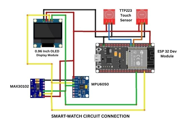
This diagram presents a comprehensive wearable health monitoring device built around an ESP32 Dev Module as the central processing unit. The system integrates multiple sensors including an MPU6050 accelerometer/gyroscope for motion tracking and step counting, a MAX30102 pulse oximeter for heart rate and blood oxygen monitoring, and two TTP223 capacitive touch sensors for user interface control. A 0.96-inch OLED display module provides visual feedback for sensor readings and user interactions. The I2C communication protocol (indicated by the shared SCL and SDA lines in yellow and green) enables efficient data exchange between the ESP32 and the sensors, while the touch sensors connect via digital pins for input detection, creating a functional smartwatch capable of fitness tracking and health monitoring.
Automation Circuit Connection:
The ESP32-based automation circuit controls home appliances such as lights, forming the smart home component of the system. Through MQTT communication, parents can remotely control appliances from the dashboard, and the smartwatch can also trigger actions automatically for example, turning on lights during a fall detection event. This setup enhances safety, accessibility, and convenience, especially for physically challenged children who may find it difficult to operate traditional switches, thereby creating a fully interconnected and responsive child safety ecosystem.
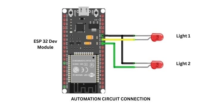
This circuit demonstrates a simple but effective home automation system using an ESP32 Dev Module to control two LED lights independently. The ESP32's GPIO pins are connected directly to the LEDs through current-limiting resistors (shown as part of the circuit), with each LED having its own dedicated control line. The green wire represents the common ground connection shared between the ESP32 and both lights, while separate control wires (yellow and additional lines) allow independent switching of each light. This basic configuration can be expanded to control more devices and serves as a foundation for IoT-based smart home
Hardware Assembly
The hardware assembly is completed in three main stages, ensuring each module works independently before integrating them into one connected child safety system. It's important to note that the hardware components presented in this project represent the minimal setup required to demonstrate the core functionality of the Child Safety Hub. This streamlined configuration includes only the essential sensors and modules needed to establish basic health monitoring, environmental tracking, camera surveillance, and home automation capabilities. While this minimal setup effectively proves the concept and provides foundational child safety features, the modular design allows for future expansion and enhancement additional sensors such as GPS trackers, more sophisticated environmental monitors, multiple camera units, or expanded home automation devices can be easily integrated as needed to create a more comprehensive safety system tailored to specific requirements and use cases.
_0.jpg)
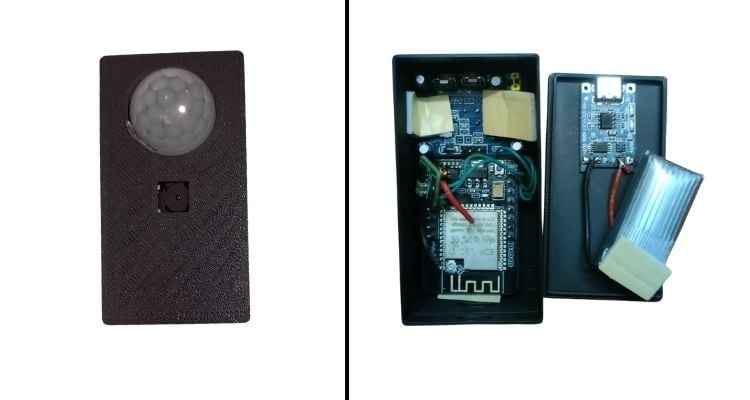
ESP32-CAM Surveillance Module
The 3.7V Li-Po battery is connected to the TP4056 charging module for safe charging, and its output is boosted to 5V using a step-up converter to power the ESP32-CAM. The PIR sensor is connected to a GPIO pin to detect motion, with a common ground shared across all components. After secure soldering and enclosure, the module activates the camera only when movement is detected, ensuring energy-efficient indoor monitoring.
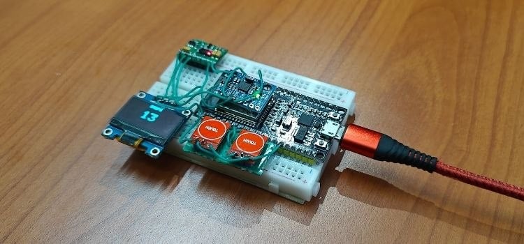
Smartwatch Module
The ESP32 Dev Module acts as the controller. The MAX30102 (SpO₂ and heart rate) and MPU6050 (motion and fall detection) are connected via shared I2C lines along with the 0.96-inch OLED display. Touch sensors are connected to GPIO pins for user input and appliance control. The components are arranged compactly to form a comfortable wearable device.
Final Integration
After testing each module individually, all ESP32 devices are connected to the same Wi-Fi network and configured using MQTT, enabling seamless communication between the smartwatch, camera, automation system, and parental dashboard.
Code Architecture and Flow Explanation
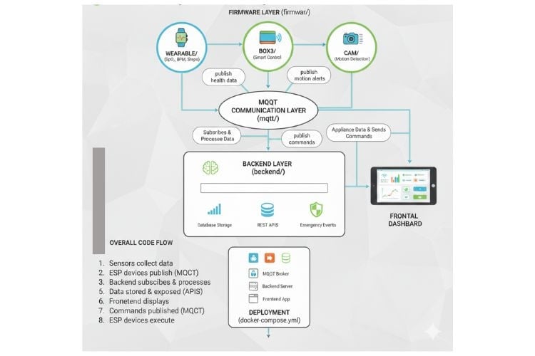
The AI Child Safety Smart Home System follows a modular and scalable IoT architecture where each component is separated into firmware, backend, frontend, and communication layers. The repository is structured to clearly divide device-level programming from server-side processing and user interface management. This separation ensures easy development, debugging, scalability, and future upgrades.
ai-child-safety-smart-home/
│
├── firmware/
│ ├── box3/
│ ├── wearable/
│ └── cam/
│
├── backend/
│
├── frontend/
│
├── mqtt/
│
├── docker-compose.yml
└── README.md
Frontend Layer (frontend/)
The frontend provides a web-based parental dashboard for real-time monitoring and control.
- Displays live health data (SpO₂, BPM, steps)
- Shows motion detection alerts
- Allows remote control of home appliances
- Provides emergency notifications
It communicates with the backend APIs to fetch data and send commands.
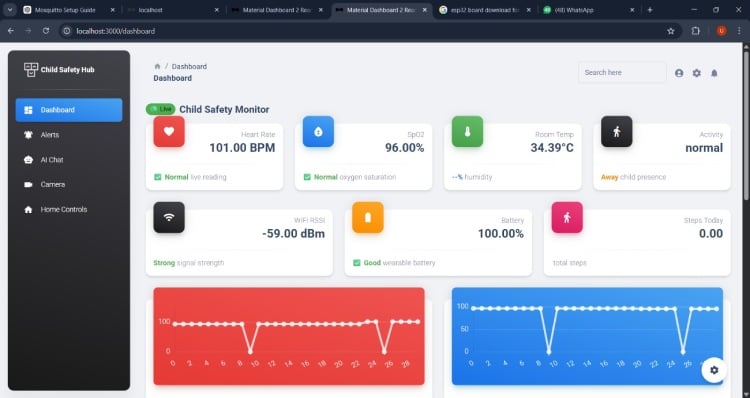
This comprehensive Child Safety Monitor dashboard provides parents and caregivers with real-time monitoring of a child's vital health metrics and environmental conditions through an intuitive web interface. The dashboard displays critical health data including heart rate (101 BPM), blood oxygen saturation (SpO2 at 96%), and activity tracking with step counting capabilities, all collected from the wearable smartwatch device. Environmental monitoring tracks room temperature (34.39°C) and humidity levels to ensure optimal conditions for the child's comfort and safety. The system also monitors the wearable device's battery status (100%) and WiFi signal strength , ensuring continuous connectivity and device reliability. Additional features include activity detection showing whether the child is present or away, live status indicators for normal readings, and historical trend charts displaying heart rate and SpO2 patterns over time. The sidebar navigation provides quick access to alerts, AI-powered chat assistance, camera feeds, and home automation controls, creating an all-in-one platform for comprehensive child safety monitoring that integrates data from the ESP32-based smartwatch and environmental sensors into a unified, user-friendly interface accessible from any web browser.
Parental Dashboard – Home Controls Interface
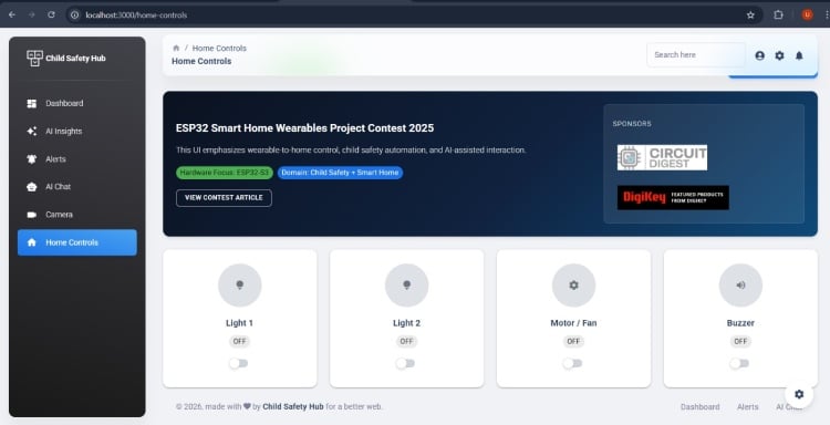
The above image shows the Home Controls section of the Child Safety Hub web dashboard running locally (localhost:3000). This interface acts as the centralized control panel for managing smart home devices connected to the AI-Enhanced Child Safety System.
The left-side navigation panel provides access to key modules such as Dashboard, AI Insights, Alerts, AI Chat, Camera, and Home Controls, enabling parents to monitor and control different parts of the system from a single interface. In the Home Controls page, individual control cards are displayed for connected devices including:
- Light 1
- Light 2
- Motor / Fan
- Buzzer
Each device card shows its current ON/OFF status along with a toggle switch for remote operation. When a toggle is activated, the dashboard sends a request to the backend, which then publishes a control message via MQTT to the corresponding ESP32 automation module. The device executes the command instantly, ensuring real-time response. For initial hardware validation, the system was tested using two LEDs representing Light 1 and Light 2. These LEDs were connected to the ESP32 automation module through GPIO pins, and remote switching was successfully verified through the dashboard. The LEDs responded instantly to ON/OFF commands, confirming proper MQTT communication, backend integration, and hardware control functionality. Overall, this interface demonstrates reliable smart home control integrated with the wearable and surveillance system, providing parents with centralized, real-time appliance management within the child safety ecosystem.
Backend Layer (backend/)
The backend acts as the central processing unit of the system. It receives data from ESP devices via MQTT and processes it for storage and dashboard display.
- Subscribes to health and motion MQTT topics
- Processes emergency events (fall detection, abnormal vitals)
- Stores data in a database
- Provides REST APIs for the frontend
- Sends control commands back to devices
This layer bridges IoT devices and the parental dashboard.
Firmware Layer (firmware/)
The firmware folder contains embedded programs for all ESP-based hardware modules, including the ESP32-S3 Box 3, smartwatch, and ESP32-CAM. Each module operates independently but communicates through MQTT.
- box3/ – Handles ESP32-S3 Box 3 operations, Wi-Fi connectivity, MQTT communication, and smart control interactions.
- wearable/ – Reads sensor data (SpO₂, BPM, step count, fall detection), displays values on OLED, and publishes health data via MQTT.
- cam/ – Detects motion using the PIR sensor, captures images, and sends motion alerts through MQTT.
All firmware modules publish and subscribe to MQTT topics, enabling real-time inter-device communication.
In the firmware section, before uploading the code to any ESP32 device, you must update the Wi-Fi credentials and MQTT broker IP address according to your network configuration. These settings are usually defined at the top of the main program file (such as main.cpp, main.c, or config.h) inside each firmware folder (box3/, wearable/, and cam/).
You should locate and modify the following parameters:
- Wi-Fi SSID → Replace with your router’s network name
- Wi-Fi Password → Replace with your router’s password
- MQTT Broker IP Address → Replace with the IP address of the system running theMQTT broker (for example, your PC or server running Docker)
Typically, the configuration section looks similar to:
const char* ssid = "YOUR_WIFI_NAME";
const char* password = "YOUR_WIFI_PASSWORD";
const char* mqtt_server = "192.168.1.100";
If you are using Docker, ensure that:
- The MQTT broker container is running.
- The IP address matches the host machine’s local IP (check using ipconfig or ifconfig).
- All ESP32 devices are connected to the same Wi-Fi network.
This update must be done in all firmware modules (box3, wearable, and cam) before flashing the devices to ensure proper connectivity and communication within the IoT system.
MQTT Communication Monitoring (MQTT Explorer View)
The image shows the real-time MQTT communication flow of the AI-Enhanced Child Safety Wearable and Smart Home System using MQTT Explorer. The broker is running at the local IP address 192.168.1.20, and all ESP32 devices are connected to this broker for data exchange. Under the child/001 topic, different subtopics manage system data:
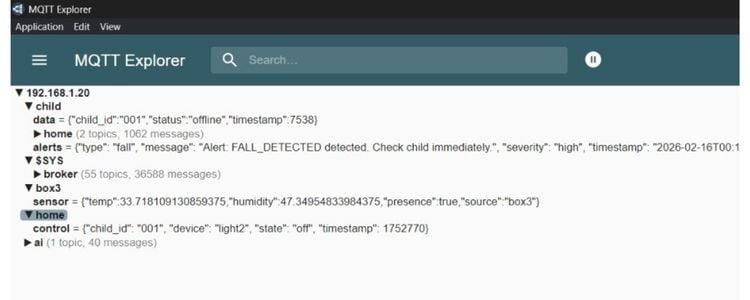
- data/ → Publishes child status information such as online/offline state and timestamps.
- home/ → Contains health and environment data including temperature, humidity, and presence detection from the Box3 module.
- alerts/ → Sends emergency notifications such as “FALL_DETECTED” with severity level and timestamp.
- control/ → Receives appliance control commands (e.g., turning light2 ON/OFF).
- ai/ → Handles AI-related messages or interactions.
The $SYS and broker topics show system-level broker statistics such as total messages and active topics. This MQTT topic structure demonstrates how the wearable, camera, and automation modules publish sensor data and alerts, while the backend and dashboard subscribe to relevant topics. Similarly, control commands from the dashboard are published to specific control topics and executed by ESP32 devices in real time. Overall, the image verifies successful device connectivity, structured topic management, and efficient real-time communication within the complete IoT ecosystem.
Emergency Alert System - Panic Button & Fall Detection for Immediate Response
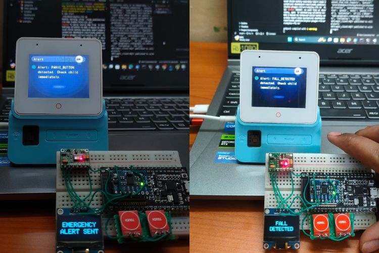
This critical safety feature integrates dual emergency alert mechanisms designed to provide immediate assistance during life-threatening situations. The system includes two prominent red panic buttons that can be pressed by the child or caregiver to manually trigger an emergency alert, instantly notifying parents or guardians through the dashboard with a "PANIC_BUTTON detected. Check child immediately" message. Additionally, the smartwatch's MPU6050 accelerometer/gyroscope sensor provides automatic fall detection capabilities, analyzing motion patterns to identify sudden impacts or unusual movements that may indicate a fall or accident, triggering an automatic "FALL detected. Check child immediately" alert without requiring any manual intervention. Both alert types are displayed on a dedicated OLED screen showing "EMERGENCY ALERT SENT" or "FALL DETECTED" confirmation, while simultaneously sending real-time notifications through the web dashboard and potentially via additional communication channels like SMS or email. The system uses visual feedback through LED indicators and the display screen to confirm alert transmission, ensuring caregivers are immediately aware of emergencies even when not actively monitoring the dashboard, making this feature an essential life-saving component that combines proactive fall detection technology with accessible manual panic activation for comprehensive emergency response coverage.
Conclusion
The AI-Enhanced Child Safety Wearable and Smart Home System successfully integrates health monitoring, indoor surveillance, and home automation into a single interconnected IoT ecosystem. By combining a smartwatch capable of monitoring SpO₂, heart rate, step count, and fall detection with a motion-detection camera and ESP32-based home automation modules, the system ensures continuous supervision and rapid emergency response. Through MQTT-based real-time communication and a centralized parental dashboard, parents can remotely monitor their child’s health, receive instant alerts, and control home appliances from anywhere.
This project demonstrates how embedded systems, IoT communication, and smart interfaces can be combined to create a cost-effective, scalable, and reliable child safety solution especially beneficial for physically challenged children and those staying alone at home. It highlights the practical application of real-time monitoring, device-to-device communication, and centralized control in modern smart home environments.
Future Upgrades
The system can be further enhanced with advanced features to improve intelligence, automation, and scalability:
- AI-Based Health Analysis – Implement machine learning algorithms to detect abnormal health patterns and predict potential risks.
- Voice Assistant Integration – Add voice interaction using ESP32-S3 Box for emergency voice commands or parental communication.
- Live Video Streaming – Upgrade the ESP32-CAM to support secure real-time streaming with cloud storage.
- Mobile Application – Develop a dedicated Android/iOS app for improved accessibility and push notifications.
- Cloud Integration – Store long-term health data on cloud platforms for analytics and history tracking.
- GPS Tracking – Integrate a GPS module for outdoor child location tracking.
- Automated Emergency Response – Enable automatic SMS/call alerts to parents or emergency contacts during critical events.
- Advanced Smart Home Expansion – Add control for fans, door locks, gas leak sensors, smoke detectors.
With these enhancements, the system can evolve into a comprehensive AI-driven child safety and smart living platform suitable for real-world deployment at scale.
