
By Shreerama T D
Every year, farmers work for months under the sun, investing their time, money, and effort to grow crops that feed the nation. But after harvesting, a painful reality unfolds a significant portion of onions and tomatoes never reach the market. Instead, they silently rot inside storage warehouses.
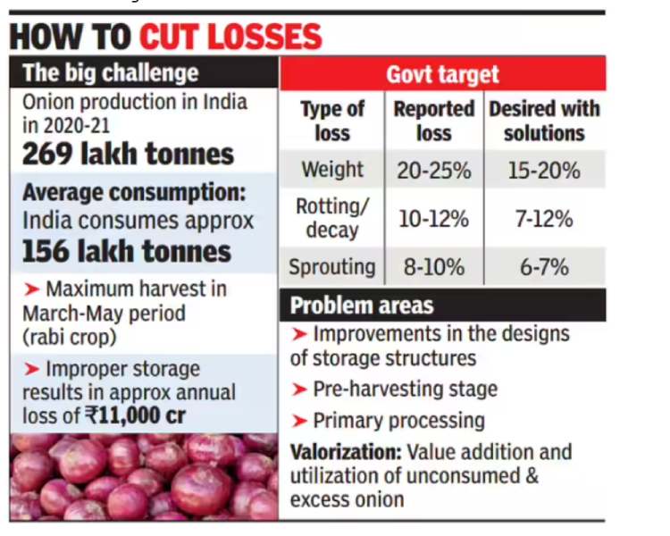
According to national data, India produces nearly 269 lakh tons of onions annually, yet 10–12% are lost due to rotting and decay, primarily because spoilage is detected too late. Improper storage alone causes losses of over ₹11,000 crore every year.
For small and marginal farmers, this is not just food waste it is the loss of income, opportunity, and months of hard work. While exploring ideas for this competition, I noticed that most IoT and AI projects focus on comfort, convenience, or smart home automation. However, I kept thinking about a more fundamental question:
Technology has advanced enough to explore space, power AI assistants, and automate homes — but why are farmers still losing their harvests to simple storage problems?
Coming from an agricultural background, I have personally seen how farmers celebrate harvest day with hope, only to suffer losses later when produce spoils inside storage rooms. Healthy onions that took months to grow start rotting silently, and by the time the damage is visible, it is already too late. Standing inside local storage yards and watching perfectly healthy produce slowly turn into waste made me realize something deeply:
The problem is not production ,The problem is protection after harvest.
Instead of building another smart home device or wearable gadget, I wanted to build something that directly protects a farmer’s income.
So I asked myself:
“If we can detect objects in space, why can’t we detect a rotting onion early and save a farmer’s income?”
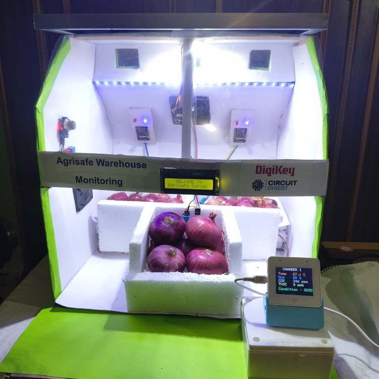
This simple question became the foundation of: AgriSafe Rot-Spotter
A low-cost, offline, Edge-AI powered smart warehouse monitoring system that detects spoilage days before it becomes visible, giving farmers time to act and prevent losses.
Instead of waiting for heat, smell, or visible mold, the system continuously monitors:
chemical emissions (VOCs)
environmental conditions (temperature & humidity)
and visual texture changes using on-device AI vision
All intelligence runs directly on the device (Edge Processing) without any cloud dependency.
This ensures:
- faster response
- higher reliability
- complete offline operation
- and suitability for rural warehouses where internet connectivity is limited or unavailable
To further support real-world agricultural environments, the system is designed with hybrid solar power capability, allowing it to operate using renewable energy with battery backup. This makes the solution:
- energy-efficient
- cost-effective
- sustainable
- and deployable even in remote farm locations
By identifying spoilage at its earliest stage, workers can:
- isolate affected crates
- improve ventilation
- prevent fungal spread
- and save healthy produce before losses occur
Real Impact
Even a modest 5% reduction in spoilage can save:
- 13+ lakh tonnes of onions annually,
- thousands of crores of rupees,
- and significantly increase farmers’ income.
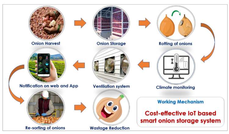
At scale, this solution can transform traditional warehouses into smart, preventive storage systems, reducing food waste, improving post-harvest management, and strengthening India’s food security. AgriSafe Rot-Spotter is not just another IoT project.While many systems automate homes,we chose to protect harvests.
It is a small but meaningful engineering step toward:
- Saving crops
- Saving money
- Saving farmers’ livelihoods
- Promoting sustainable, solar-powered agriculture
The Newspaper Screenshot

Vegetables such as onions, potatoes, and tomatoes also contribute significantly to the total losses, with ₹5,156 crore lost from onions alone and ₹5,921 crore from tomatoes.
Read Article on
Overview
AgriSafe Rot-Spotter is a multi-modal smart warehouse monitoring system designed to detect early spoilage of onions and vegetables inside storage facilities. The system combines gas sensing, temperature monitoring, and Edge-AI vision to identify rot before it becomes visible to humans. Each chamber uses an ESP32-CAM node running an offline machine learning model, while all nodes communicate wirelessly to a central ESP32-S3-BOX hub using ESP-NOW. The entire processing is performed locally without cloud dependency, ensuring fast and reliable operation in rural areas. Powered by a hybrid solar-battery system, the solution enables low-cost, scalable, and energy-efficient deployment for multi-chamber warehouses.
Problem Statement
Post-harvest spoilage is one of the biggest hidden losses in Indian agriculture. Most storage warehouses rely only on basic temperature or humidity monitoring, which is insufficient for detecting early biological decay. Fungal infections and fermentation processes release chemical gases long before visible mold appears, but traditional systems fail to sense these early indicators. As a result, spoilage is detected only after the damage has already spread, leading to significant financial losses for farmers. Small and rural storage units lack smart monitoring solutions and internet connectivity, making cloud-based systems impractical. Therefore, there is a strong need for an affordable, offline, early-warning system that can detect spoilage proactively and prevent post-harvest losses.
Key Features
- Early VOC-based spoilage detection
- Offline Edge-AI image classification on ESP32-CAM
- Multi-chamber wireless monitoring using ESP-NOW
- Zero cloud dependency (fully local processing)
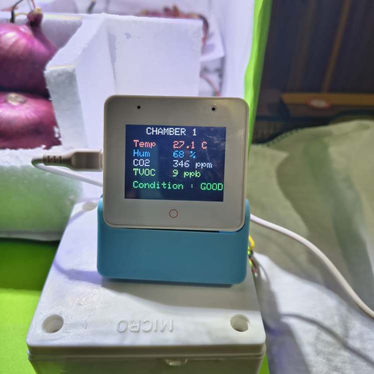
- Real-time visual dashboard on ESP32-BOX display
- Voice alerts for workers
- Automatic fan control for ventilation
- Hybrid solar + battery powered operation
- Scalable design for multiple storage rooms
- Low-cost and rural-friendly implementation
Components Required
Core Processing Units:
- ESP32-S3-BOX-3 Development Board × 1
- ESP32-CAM Modules × 3
- ESP8266 Wi-Fi Module × 1
- FTDI USB-to-Serial Programmer (FT232/CP2102) × 1
Sensors:
- SGP30 VOC & eCO₂ Gas Sensor Modules × 3
- DHT11 Temperature & Humidity Sensors × 4
Actuators & Indicators:
- 5V DC Cooling Fans × 3
- Relay/Transistor Driver Modules (Fan Control) × 3
- White LED Strips/LED Modules (Camera Lighting)
- Toggle Switches × 2
- I2C LCD Display Module × 1
Power Management:
- LM2596 Buck Converter (Step-Down Module) × 3
- TP4056/TP5100 Lithium Battery Charger Module × 1
- Lithium-Ion Cells 3.7V (18650) × 3
- Solar Panel (6–12V, 10W) × 1
- 470µF Electrolytic Capacitors (Power Stabilization) × 3
Communication & Wiring:
- USB Cables (Micro-USB/Type-C) × 1
- Jumper Wires (Male-Male, Male-Female Set) × 1 set
- Hook-up Wires (Red/Black) × 1 roll
- Resistors & Capacitors (Assorted Pack) × 1 set
Mechanical & Enclosure:
- PVC Plastic Enclosure Box (Main Hub Housing) × 1
- Thermocol/Foam Sheets (Warehouse Chamber Insulation) × As required
- Drawing Sheets/Cardboard Sheets (Structure Prototype) × As required
- Mounting Screws & Spacers × 1 set
Tools & Accessories:
- Soldering Iron × 1
- Solder Wire × 1
- Solder Sucker × 1
- Hot Glue Gun × 1
- Gum/Fevicol × 1
- Screwdriver Set × 1
- Wire Cutter/Stripper × 1
- Multimeter (Testing) × 1
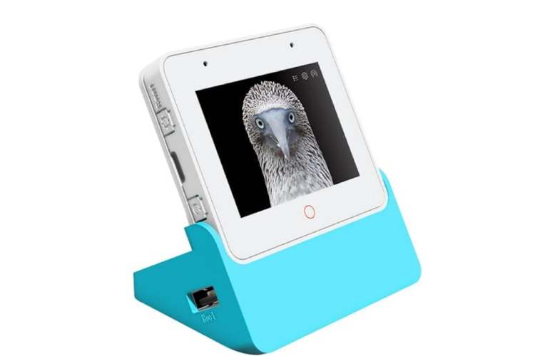
Reasons For Choosing Espressif Systems ESP32-S3-BOX-3 For My AgriSafe Rot-Spotter Project
ESP32-S3-BOX-3
Circuit Digest provided multiple development platforms for building the solution. For Agri-Safe Rot-Spotter, I selected the ESP32-S3-BOX-3 because it combines Edge AI capability, human interaction features, and wireless connectivity a single compact board, making it ideal for an intelligent smart-warehouse hub.
Powerful Edge-AI Processor
USB- + Multiple Interfaces
Large RAM + PSRAM for Vision Tasks
Integrated Wi-Fi, Bluetooth & ESP-NOW
Built-in Touch Display (Human Interface)
Microphone + Speaker for Offline Voice Interaction
All-in-One Compact Solution
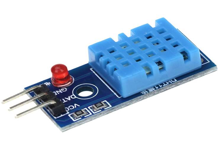
DHT11 Temperature & Humidity Sensor
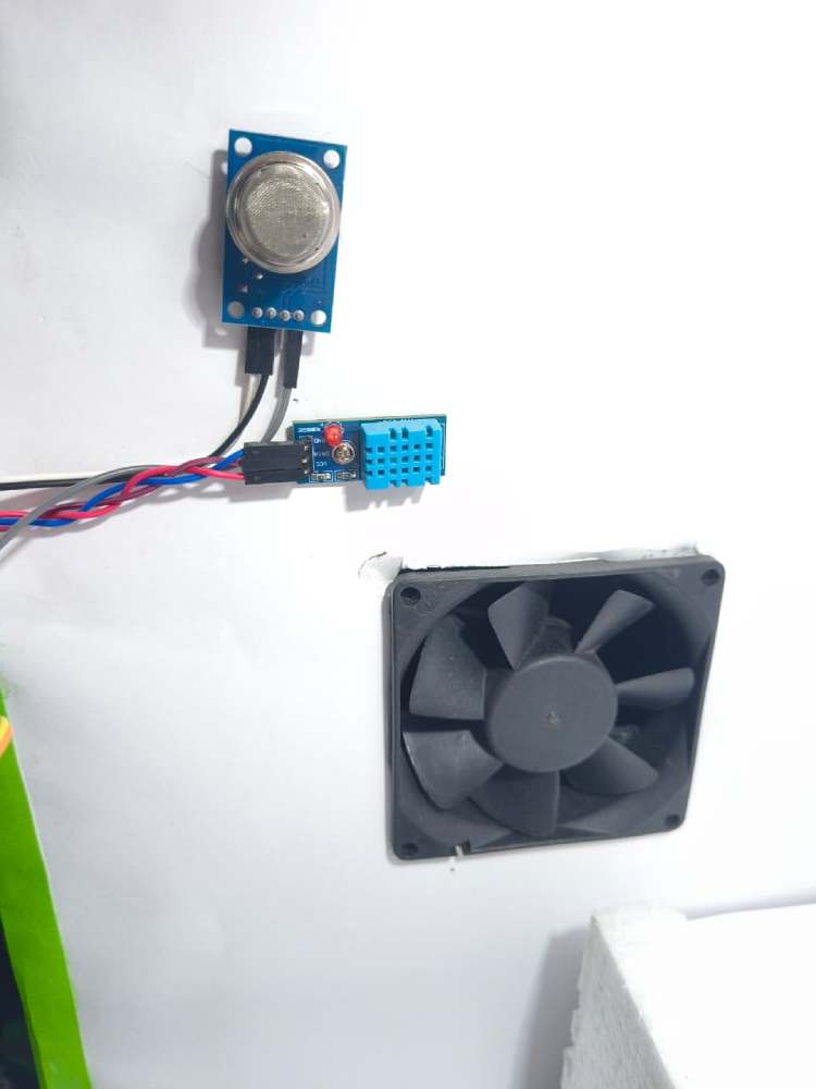
The DHT11 provides real-time ambient temperature and humidity readings inside each storage chamber. Temperature rise and high humidity accelerate fungal growth and decay, so monitoring these parameters helps maintain safe storage conditions. It offers simple digital output and stable readings with minimal calibration. The sensor also controls automatic ventilation by activating fans when thresholds are exceeded
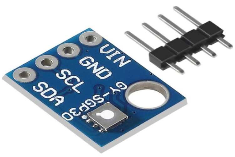
SGP30 VOC & eCO₂ Gas Sensor
The SGP30 is a digital air-quality sensor designed to measure Total Volatile Organic Compounds (TVOC) and equivalent CO₂ levels. It uses a metal-oxide sensing element to detect early chemical emissions produced during fermentation and spoilage. Since onions release VOCs before visible Mold appears, this sensor enables early-stage detection (2–3 days earlier than human inspection). It communicates via I²C with low power consumption and high sensitivity in the ppb range. This makes it the primary early warning indicator in our system
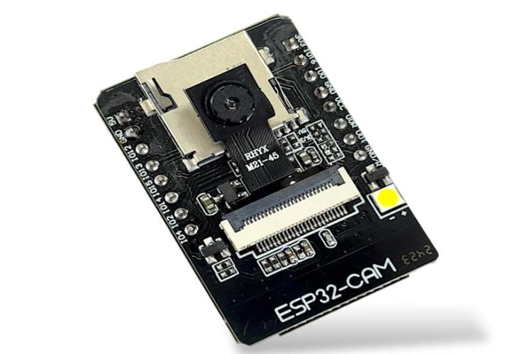
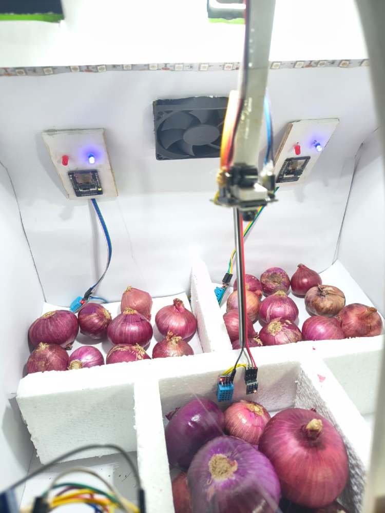
ESP32-CAM Modules (Vision Sensor Nodes)
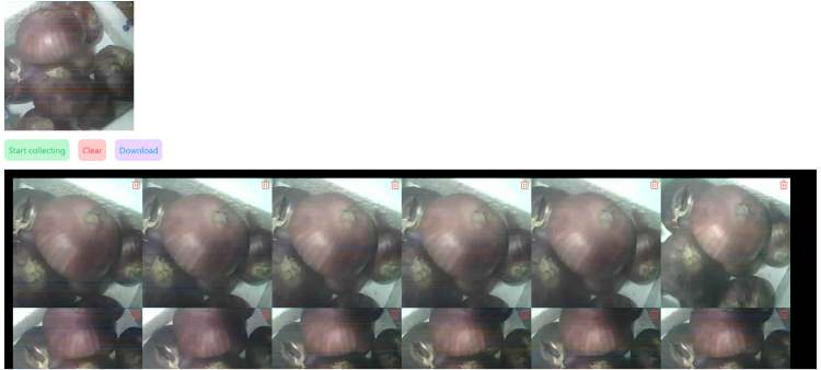
The ESP32-CAM modules are deployed inside each storage chamber to capture real-time images of the onions. Each board integrates an ESP32 processor with an OV2640 2MP camera, supporting JPEG image capture with low memory usage. These modules run a lightweight offline ML classification model locally, allowing detection of healthy vs rotten produce without sending heavy image data continuously
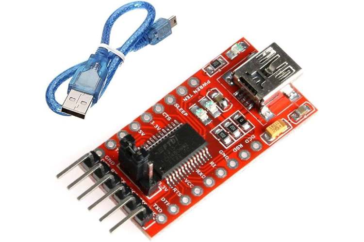
FTDI USB-to-Serial Programmer
The FTDI programmer is used to upload firmware and debug ESP32-CAM modules that lack native USB interfaces. It provides reliable serial communication for flashing, testing, and troubleshooting. This tool ensures faster development cycles and easier maintenance. Including a dedicated programmer makes the system professional and field serviceable
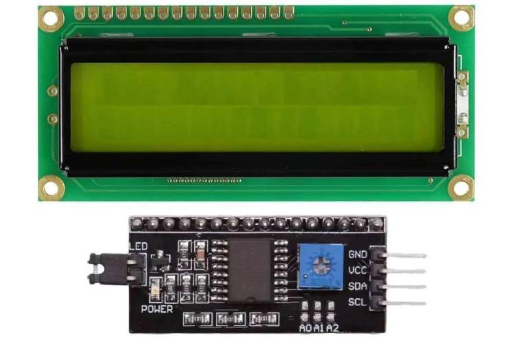
I²C (16x2) LCD display
It is used as a compact real-time monitoring interface to show environmental parameters directly at the warehouse node level. It continuously displays temperature, humidity, and air quality values measured by the DHT11 and MQ-135 sensors, allowing workers to instantly assess storage conditions without requiring a mobile app or central dashboard.
The display communicates using the I²C protocol (SDA, SCL), which reduces wiring complexity and uses only two communication lines, making integration with ESP8266 modules simple and reliable.
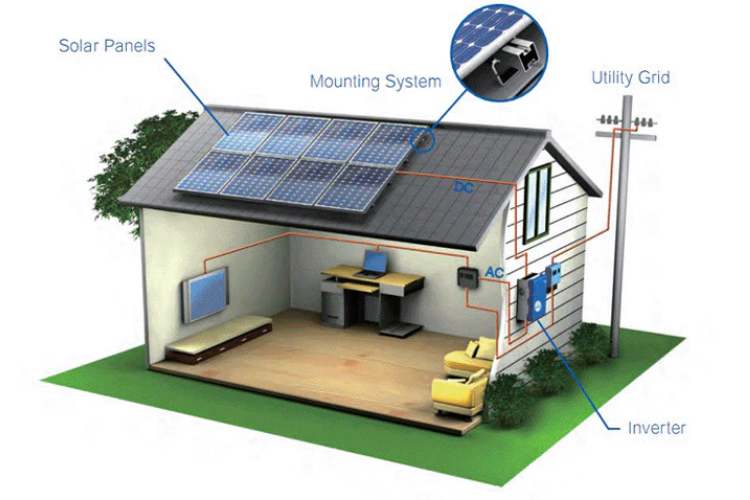
Solar Panel + Lithium Battery (Hybrid Power System)
The system uses a small solar panel combined with lithium-ion battery cells to provide hybrid renewable power. During the day, solar energy charges the batteries, while the battery ensures uninterrupted operation at night or during power failures. This design eliminates dependency on grid electricity and makes the solution suitable for rural and remote farm locations. It also reduces operational costs and promotes sustainable, eco-friendly deployment. The hybrid approach ensures 24/7 monitoring reliability.
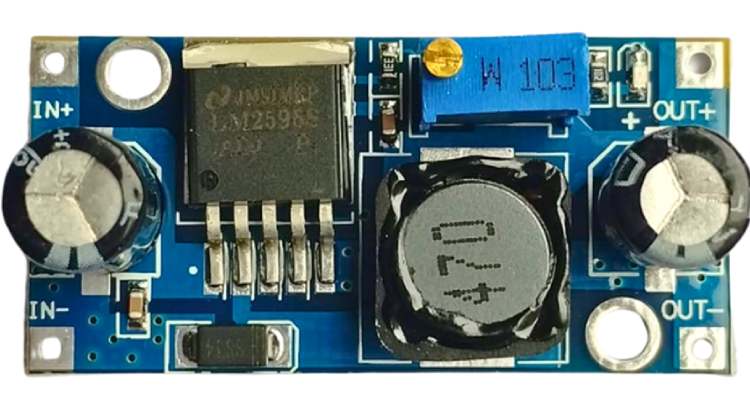
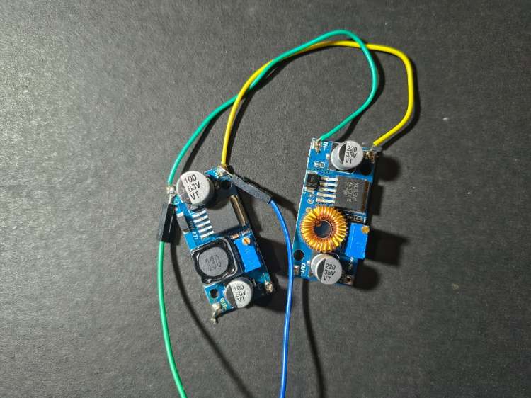
LM2596 Buck Converter (Step-Down Regulator)
The LM2596 buck converter efficiently steps down battery voltage to stable 5 V/3.3 V levels required by the ESP modules and sensors. It provides high efficiency (~80–90%) with minimal heat dissipation compared to linear regulators. This ensures longer battery life and stable operation during camera and Wi-Fi current spikes. It also protects sensitive electronics from voltage fluctuations. Using a switching regulator significantly improves overall power management
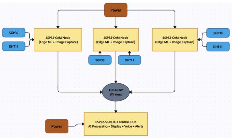
Block Diagram
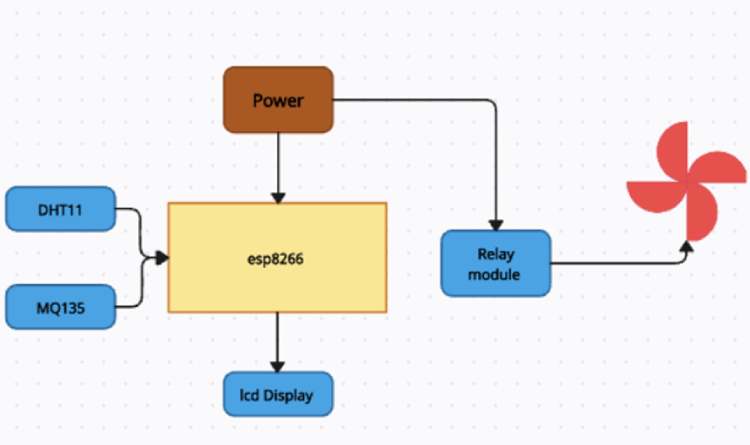
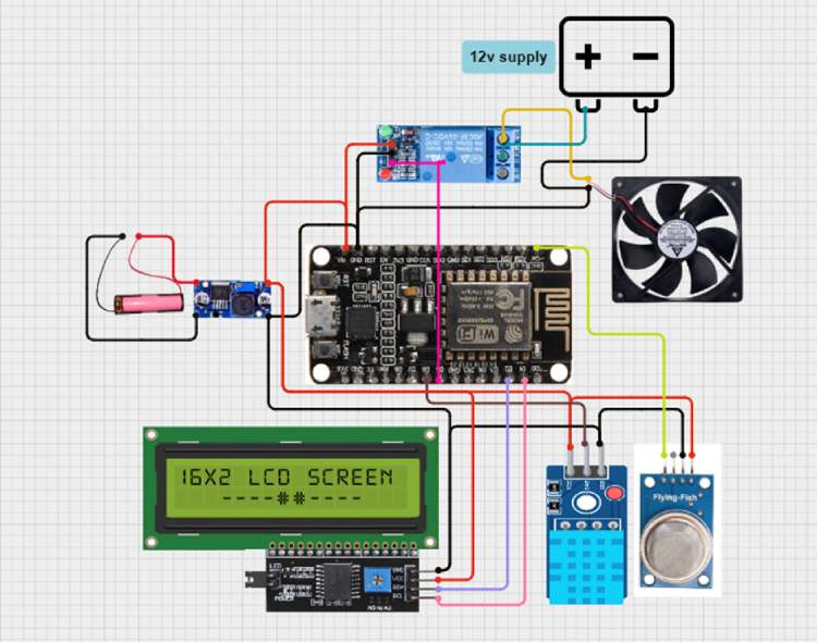
Circuit Diagram

Working Principle
AgriSafe Rot-Spotter operates on the principle of multi-modal sensor fusion combined with Edge-AI based early spoilage detection. Instead of relying only on temperature monitoring, the system intelligently combines chemical sensing, environmental monitoring, and visual analysis to detect spoilage at its earliest stage. The entire decision-making process is performed locally on embedded devices without cloud dependency, ensuring fast, reliable, and offline operation suitable for rural warehouses.
The system architecture consists of multiple ESP32-CAM based sensing nodes installed inside each storage chamber and one central ESP32-S3-BOX smart hub that performs aggregation, visualization, and alert handling.
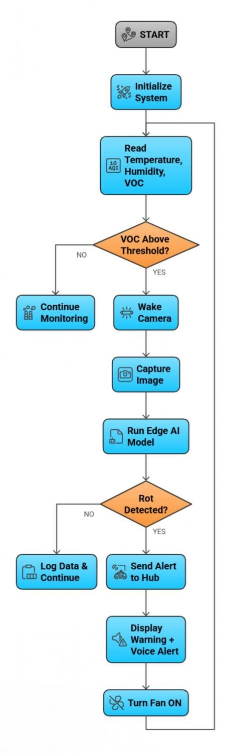
Step-by-Step Working Process
1. System Initialization
When powered ON through the hybrid solar-battery supply, the ESP32-S3-BOX hub and all ESP32-CAM nodes initialize sensors, communication modules, and machine learning models. Wireless communication is established between all nodes using the ESP-NOW protocol.
2. Continuous Environmental Monitoring
Each chamber node continuously reads:
- Temperature and humidity using DHT11
- VOC and air quality using SGP30/MQ-135
These sensors operate at low power and provide real-time environmental information. Under normal conditions, the system remains in monitoring mode to conserve energy.
3. Early Chemical Detection
During spoilage, onions and vegetables release volatile organic compounds (VOCs) and fermentation gases before visible mold appears. The SGP30 detects these chemical emissions at ppm/ppb levels.
When the VOC concentration exceeds a predefined threshold:
- It indicates possible microbial activity
- The system flags the chamber as “suspicious”
- The vision module is activated
This prevents unnecessary camera usage and improves battery life.
4. Intelligent Camera Activation
Instead of continuously running the camera, the ESP32-CAM wakes only when abnormal gas levels are detected. This event-driven approach:
- reduces power consumption
- increases efficiency
- extends hardware life
The camera captures high-resolution images of the onion crates for analysis.
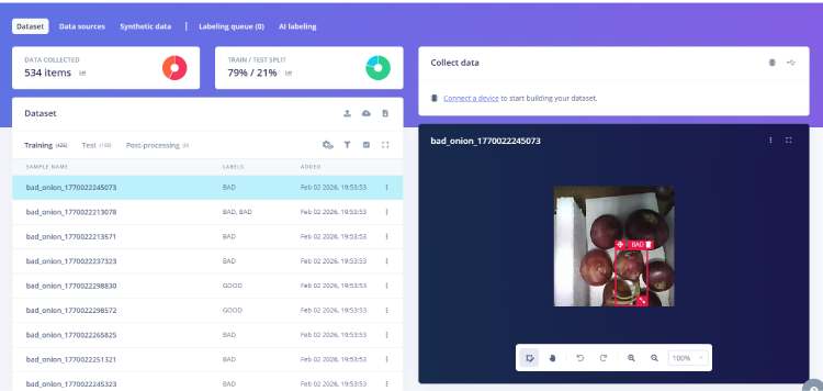
5. Edge AI Image Processing
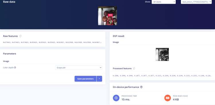
The captured image is processed locally using an Edge Impulse TinyML model deployed on the ESP32-CAM.
The model:
- extracts visual features (color, texture, mold spots, surface damage)
- compares with trained healthy/rotten dataset
- performs classification
Output:
- Healthy
- Early Rot
- Rotten
Since inference runs locally, the system provides instant results without internet latency.
6. Wireless Data Transmission
After classification, only essential data (sensor values + result) is transmitted to the central hub using ESP-NOW. This protocol provides:
- low latency
- low power
- internet-free communication
- reliable short-range networking
This makes the system suitable for rural and indoor warehouse environments.
7. Central Sensor Fusion & Decision Making
The ESP32-S3-BOX hub receives inputs from all chambers and performs sensor fusion. It correlates:
- gas levels
- temperature
- humidity
- AI classification result
If multiple indicators confirm spoilage, the hub marks the chamber as “Alert”.
This reduces false alarms and improves accuracy.
8. Alert & User Notification
When spoilage is confirmed, the hub immediately:
- displays warning on touchscreen
- shows chamber number and status
- announces voice alert using speaker
- logs the event
This ensures that workers are instantly informed, even without checking screens.
9. Automatic Environmental Control
Simultaneously, the system activates:
- ventilation fans through relay control
This improves airflow and slows fungal spread, protecting nearby healthy produce. When values return to safe levels, fans automatically turn OFF.
10. Continuous Monitoring Cycle
After handling the alert, the system returns to monitoring mode and repeats the cycle continuously. This 24/7 operation ensures proactive detection and prevention of spoilage.
Software Requirements
The system software is developed using embedded IoT and Edge-AI tools to enable offline processing, wireless communication, and real-time monitoring.
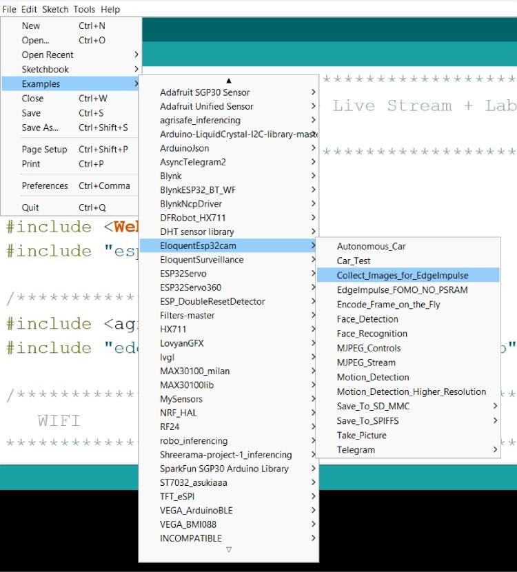
Development Tools
- Arduino IDE (firmware programming)
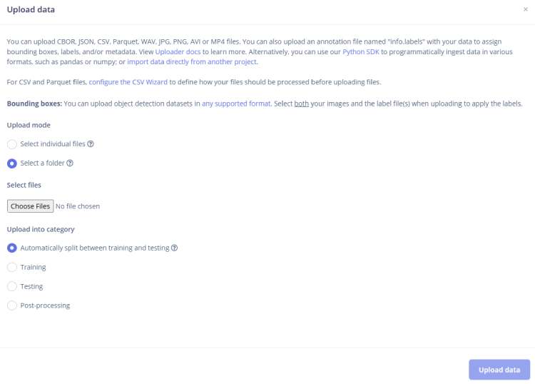
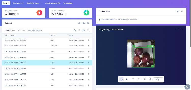
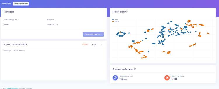
- Edge Impulse Studio (model training and deployment)
- GitHub (code version control and sharing)
Libraries & Frameworks
- WiFi.h – wireless connectivity
- esp_now.h – low-latency device-to-device communication
- Wire.h – I²C communication for sensors/display
- LVGL – graphical user interface for ESP32-S3-BOX display
- Audio/I2S libraries – voice alerts and speaker control
- Edge Impulse SDK – TinyML inference engine
- DHT sensor library – temperature/humidity readings
- Adafruit SGP30 library – VOC gas sensing


Components Required
| Component Name | Quantity | Datasheet/Link |
| ESP32-CAM Module | 3 | - |
| SGP30 VOC Gas Sensor | 3 | - |
| DHT11 Temperature & Humidity Sensor | 3 | - |
| DC Fans/Relay Board / Transistor Driver | 3 | - |
| Buck Converter (LM2596) | 3 | - |
| I2C (16X2) LCD Display Module | 1 | - |
| Lithium-ion Cell 3.7V (18650)/Charger Module (TP4056/TP5100) | 3 | - |
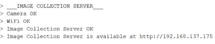
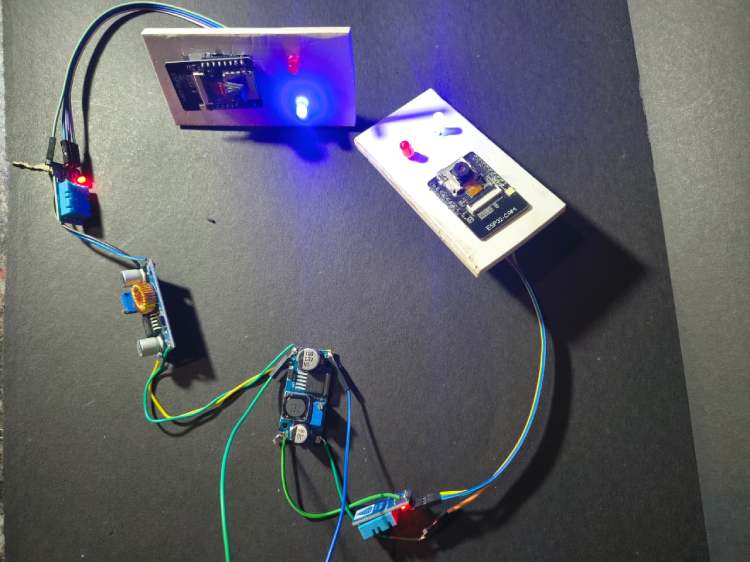
Hardware Assembly
Code Explanation
ESP32-CAM Smart Agriculture Safety Node – Code Explanation
This project implements a real-time AI-enabled safety monitoring system using ESP32-CAM.
The device simultaneously performs:
- Environmental sensing (Temperature, Humidity, CO₂, TVOC)
- AI object detection (Edge Impulse model)
- Wireless transmission using ESP-NOW
The ESP32 runs dual-core FreeRTOS multitasking so sensing and AI vision work in parallel without delay.
1. Libraries Used
#include <Wire.h>
#include<DHT.h>
#include"SparkFun_SGP30_Arduino_Library.h"
#include<agrisafe_inferencing.h>
#include"edge-impulse-sdk/dsp/image/image.hpp"
#include"esp_camera.h"
#include <WiFi.h>
#include <esp_now.h>
Purpose of each library
LibraryFunctionWire.hI2C communication (SGP30 sensor)DHT.hTemperature & humidity sensorSparkFun_SGP30Air quality sensor (CO2 & TVOC)agrisafe_inferencingEdge Impulse trained AI modelesp_cameraESP32-CAM image captureWiFi & ESP-NOWWireless communication
2. Sensor & Camera Configuration
Pin Definitions
#define SDA_PIN 15
#define SCL_PIN 14
#define DHTPIN 13
#define DHTTYPE DHT11
SensorPinsDHT11GPIO13SGP30I2C (GPIO14, GPIO15)CameraDefault ESP32-CAM pins
Data Packet Structure
All data is packed and sent wirelessly using ESP-NOW.
typedef struct {
float temp;
float hum;
uint16_t co2;
uint16_t tvoc;
char label[20]; } Packet;
The packet contains:
- Temperature
- Humidity
- CO₂ concentration
- Air quality (TVOC)
- AI detected object label
3. Setup Function
void setup()This function initializes:
1. Sensors
Wire.begin(SDA_PIN, SCL_PIN);
dht.begin();
mySensor.begin();
mySensor.initAirQuality();
2. ESP-NOW Communication
WiFi.mode(WIFI_STA);
esp_now_init();
esp_now_add_peer(&peerInfo);
ESP-NOW sends data directly to receiver ESP32 using MAC address.
3. Camera + AI Model
ei_camera_init(); Initializes OV2640 camera and prepares Edge Impulse classifier.
4. Multitasking (IMPORTANT PART)
xTaskCreatePinnedToCore(Task1code, "Task1", 4096, NULL, 1, NULL, 1); xTaskCreatePinnedToCore(Task2code, "Task2", 10000, NULL, 1, NULL, 0); CoreTaskWorkCore 1Sensor TaskReads sensors & sends dataCore 0AI TaskRuns object detection
➡ This prevents sensor delay during image processing.
4. Sensor Task (Core 1)
void Task1code(void * pvParameters) Runs every 1 second
pkt.temp = dht.readTemperature();
pkt.hum = dht.readHumidity();
pkt.co2 = mySensor.CO2;
pkt.tvoc = mySensor.TVOC;
esp_now_send(receiverMAC, (uint8_t*)&pkt, sizeof(pkt));
What happens
- Reads DHT11 temperature & humidity
- Reads SGP30 air quality
- Packs data into structure
- Sends to receiver ESP32 dashboard
5. AI Detection Task (Core 0)
void Task2code(void * pvParameters) { detect(); } Runs continuously.
6. Image Capture & AI Inference
Capture Image
ei_camera_capture(width, height, snapshot_buf); Camera captures frame → converts JPEG → RGB888
Run Edge Impulse Model
run_classifier(&signal, &result, debug_nn); The trained model detects objects like:
- • Human presence
- • Fire
- • Animal
- • Helmet / No helmet (depends on training)
If Object Found → Send Label
strcpy(pkt.label, bb.label); esp_now_send(receiverMAC, (uint8_t*)&pkt, sizeof(pkt)); So receiver dashboard instantly knows what danger occurred.
7. Camera Initialization
bool ei_camera_init() Initializes OV2640 camera with:
- • QVGA resolution
- • JPEG format
- • PSRAM frame buffer
Optimized for real-time AI inference.
8. Why Dual Core is Important
ESP32 has 2 cores:
CoreWorkCore 0AI Image ProcessingCore 1Sensors + Communication
Without this → DHT stops updating during AI detection
With this → Real-time monitoring
9. System Working Flow
Device powers ON
Sensors start monitoring air quality
Camera continuously checks environment
AI detects hazards
Data sent wirelessly to dashboard
Key Features of Firmware
- Real-time AI monitoring
- Wireless sensor network
- Dual-core multitasking
- Low latency communication
- Edge computing (No internet required)
// These sketches are tested with 2.0.4 ESP32 Arduino Core
// https://github.com/espressif/arduino-esp32/releases/tag/2.0.4
/* Includes ---------------------------------------------------------------- */
#include <Wire.h>
#include <DHT.h>
#include "SparkFun_SGP30_Arduino_Library.h"
#include <agrisafe_inferencing.h>
#include "edge-impulse-sdk/dsp/image/image.hpp"
#include "esp_camera.h"
#include <WiFi.h>
#include <esp_now.h>
/* Constant defines -------------------------------------------------------- */
#define EI_CAMERA_RAW_FRAME_BUFFER_COLS      320
#define EI_CAMERA_RAW_FRAME_BUFFER_ROWS      240
#define EI_CAMERA_FRAME_BYTE_SIZE         3
#define SDA_PIN 15
#define SCL_PIN 14
#define DHTPIN 13
#define DHTTYPE DHT11
DHT dht(DHTPIN, DHTTYPE);
SGP30 mySensor;
uint8_t receiverMAC[] = {0x88,0x13,0xBF,0x0B,0x9F,0xE0}; // change to your receiver MAC
typedef struct {
float temp;
float hum;
uint16_t co2;
uint16_t tvoc;
char label[20];
}
Packet;
Packet pkt;
/************* TIMERS *************/
unsigned long sensorTimer = 0;
unsigned long camTimer = 0;
/* Private variables ------------------------------------------------------- */
static bool debug_nn = false; // Set this to true to see e.g. features generated from the raw signal
static bool is_initialised = false;
uint8_t *snapshot_buf; //points to the output of the capture
static camera_config_t camera_config = {
 .pin_pwdn = 32,
 .pin_reset = -1,
 .pin_xclk = 0,
 .pin_sscb_sda = 26,
 .pin_sscb_scl = 27,
  .pin_d7 = 35,
  .pin_d6 = 34,
  .pin_d5 = 39,
  .pin_d4 = 36,
  .pin_d3 = 21,
  .pin_d2 = 19,
  .pin_d1 = 18,
  .pin_d0 = 5,
  .pin_vsync = 25,
  .pin_href = 23,
  .pin_pclk = 22,
 //XCLK 20MHz or 10MHz for OV2640 double FPS (Experimental)
 .xclk_freq_hz = 20000000,
 .ledc_timer = LEDC_TIMER_0,
 .ledc_channel = LEDC_CHANNEL_0,
 .pixel_format = PIXFORMAT_JPEG, //YUV422,GRAYSCALE,RGB565,JPEG
 .frame_size = FRAMESIZE_QVGA,  //QQVGA-UXGA Do not use sizes above QVGA when not JPEG
 .jpeg_quality = 12, //0-63 lower number means higher quality
 .fb_count = 1,    //if more than one, i2s runs in continuous mode. Use only with JPEG
 .fb_location = CAMERA_FB_IN_PSRAM,
 .grab_mode = CAMERA_GRAB_WHEN_EMPTY,
};
/* Function definitions ------------------------------------------------------- */
bool ei_camera_init(void);
void ei_camera_deinit(void);
bool ei_camera_capture(uint32_t img_width, uint32_t img_height, uint8_t *out_buf) ;
/**
* @brief   Arduino setup function
*/
TaskHandle_t Task1;
TaskHandle_t Task2;
void setup()
{
 // put your setup code here, to run once:
 Serial.begin(115200);
 delay(2000);
 //comment out the below line to start inference immediately after upload
 WiFi.mode(WIFI_STA);
Wire.begin(SDA_PIN, SCL_PIN);
dht.begin();
if (!mySensor.begin()) while(1);
mySensor.initAirQuality();
if (esp_now_init() != ESP_OK) {
 Serial.println("ESP NOW init failed");
 return;
}
esp_now_peer_info_t peerInfo = {};
memcpy(peerInfo.peer_addr, receiverMAC, 6);
peerInfo.channel = 0;
peerInfo.encrypt = false;
esp_now_add_peer(&peerInfo);
 while (!Serial);
 Serial.println("Edge Impulse Inferencing Demo");
 if (ei_camera_init() == false) {
   ei_printf("Failed to initialize Camera!\r\n");
 }
 else {
   ei_printf("Camera initialized\r\n");
 }
 ei_printf("\nStarting continious inference in 2 seconds...\n");
 ei_sleep(2000);
xTaskCreatePinnedToCore(Task1code, "Task1", 4096, NULL, 1, NULL, 1);
delay(1000);
xTaskCreatePinnedToCore(Task2code, "Task2", 10000, NULL, 1, NULL, 0);
delay(1000);
}
void Task1code( void * pvParameters ){
Serial.print("Task1 running on core ");
Serial.println(xPortGetCoreID());
for(;;){
 if (millis() - sensorTimer > 1000) {
 sensorTimer = millis();
 mySensor.measureAirQuality();
 pkt.temp = dht.readTemperature();
 pkt.hum = dht.readHumidity();
 pkt.co2 = mySensor.CO2;
 pkt.tvoc = mySensor.TVOC;
 esp_now_send(receiverMAC, (uint8_t*)&pkt, sizeof(pkt));
 Serial.printf("T:%.1f H:%.1f CO2:%d TVOC:%d \n",
        pkt.temp,pkt.hum,pkt.co2,pkt.tvoc);
}
}
}
void Task2code( void * pvParameters ){
Serial.print("Task2 running on core ");
Serial.println(xPortGetCoreID());
for(;;){
detect();
}
}
void loop(){
}
void detect(){
 // instead of wait_ms, we'll wait on the signal, this allows threads to cancel us...
 if (ei_sleep(5) != EI_IMPULSE_OK) {
   return;
 }
 snapshot_buf = (uint8_t*)malloc(320*240*3);
 // check if allocation was successful
 if(snapshot_buf == nullptr) {
   ei_printf("ERR: Failed to allocate snapshot buffer!\n");
   return;
 }
 ei::signal_t signal;
 signal.total_length = EI_CLASSIFIER_INPUT_WIDTH * EI_CLASSIFIER_INPUT_HEIGHT;
 signal.get_data = &ei_camera_get_data;
 if (ei_camera_capture((size_t)EI_CLASSIFIER_INPUT_WIDTH, (size_t)EI_CLASSIFIER_INPUT_HEIGHT, snapshot_buf) == false) {
   ei_printf("Failed to capture image\r\n");
   free(snapshot_buf);
   return;
 }
 // Run the classifier
 ei_impulse_result_t result = { 0 };
 EI_IMPULSE_ERROR err = run_classifier(&signal, &result, debug_nn);
 if (err != EI_IMPULSE_OK) {
   ei_printf("ERR: Failed to run classifier (%d)\n", err);
   return;
 }
 /* print the predictions
 ei_printf("Predictions (DSP: %d ms., Classification: %d ms., Anomaly: %d ms.): \n",
       result.timing.dsp, result.timing.classification, result.timing.anomaly);*/
#if EI_CLASSIFIER_OBJECT_DETECTION == 1
 //ei_printf("Object detection bounding boxes:\r\n");
 for (uint32_t i = 0; i < result.bounding_boxes_count; i++) {
   ei_impulse_result_bounding_box_t bb = result.bounding_boxes[i];
   if (bb.value == 0) {
     continue;
   }
 Serial.print("label  ");
       Serial.println(bb.label);
      strcpy(pkt.label, bb.label);
 esp_now_send(receiverMAC, (uint8_t*)&pkt, sizeof(pkt));
 }
 // Print the prediction results (classification)
#else
 ei_printf("Predictions:\r\n");
 for (uint16_t i = 0; i < EI_CLASSIFIER_LABEL_COUNT; i++) {
   ei_printf(" %s: ", ei_classifier_inferencing_categories[i]);
   ei_printf("%.5f\r\n", result.classification[i].value);
 }
#endif
 // Print anomaly result (if it exists)
#if EI_CLASSIFIER_HAS_ANOMALY
 ei_printf("Anomaly prediction: %.3f\r\n", result.anomaly);
#endif
#if EI_CLASSIFIER_HAS_VISUAL_ANOMALY
 ei_printf("Visual anomalies:\r\n");
 for (uint32_t i = 0; i < result.visual_ad_count; i++) {
   ei_impulse_result_bounding_box_t bb = result.visual_ad_grid_cells[i];
   if (bb.value == 0) {
     continue;
   }
 }
#endif
 free(snapshot_buf);
}
bool ei_camera_init(void) {
 if (is_initialised) return true;
 //initialize the camera
 esp_err_t err = esp_camera_init(&camera_config);
 if (err != ESP_OK) {
  Serial.printf("Camera init failed with error 0x%x\n", err);
  return false;
 }
 sensor_t * s = esp_camera_sensor_get();
 // initial sensors are flipped vertically and colors are a bit saturated
 if (s->id.PID == OV3660_PID) {
  s->set_vflip(s, 1); // flip it back
  s->set_brightness(s, 1); // up the brightness just a bit
  s->set_saturation(s, 0); // lower the saturation
 }
 is_initialised = true;
 return true;
}
bool ei_camera_capture(uint32_t img_width, uint32_t img_height, uint8_t *out_buf) {
 bool do_resize = false;
 if (!is_initialised) {
   ei_printf("ERR: Camera is not initialized\r\n");
   return false;
 }
 camera_fb_t *fb = esp_camera_fb_get();
 if (!fb) {
   ei_printf("Camera capture failed\n");
   return false;
 }
bool converted = fmt2rgb888(fb->buf, fb->len, PIXFORMAT_JPEG, snapshot_buf);
 esp_camera_fb_return(fb);
 if(!converted){
   ei_printf("Conversion failed\n");
   return false;
 }
 if ((img_width != EI_CAMERA_RAW_FRAME_BUFFER_COLS)
   || (img_height != EI_CAMERA_RAW_FRAME_BUFFER_ROWS)) {
   do_resize = true;
 }
 if (do_resize) {
   ei::image::processing::crop_and_interpolate_rgb888(
   out_buf,
   EI_CAMERA_RAW_FRAME_BUFFER_COLS,
   EI_CAMERA_RAW_FRAME_BUFFER_ROWS,
   out_buf,
   img_width,
   img_height);
 }
 return true;
}
static int ei_camera_get_data(size_t offset, size_t length, float *out_ptr)
{
 // we already have a RGB888 buffer, so recalculate offset into pixel index
 size_t pixel_ix = offset * 3;
 size_t pixels_left = length;
 size_t out_ptr_ix = 0;
 while (pixels_left != 0) {
   // Swap BGR to RGB here
   // due to https://github.com/espressif/esp32-camera/issues/379
   out_ptr[out_ptr_ix] = (snapshot_buf[pixel_ix + 2] << 16) + (snapshot_buf[pixel_ix + 1] << 8) + snapshot_buf[pixel_ix];
   // go to the next pixel
   out_ptr_ix++;
   pixel_ix+=3;
   pixels_left--;
 }
 // and done!
 return 0;
}
#if !defined(EI_CLASSIFIER_SENSOR) || EI_CLASSIFIER_SENSOR != EI_CLASSIFIER_SENSOR_CAMERA
#error "Invalid model for current sensor"
#endif
welcome display code
#include <Wire.h>
#include <LiquidCrystal_I2C.h>
#include <DHT.h>
#include <MQ135.h>
/************ LCD ************/
LiquidCrystal_I2C lcd(0x27, 16, 2);
/************ PINS ************/
#define DHT_PIN  12
#define FAN_PIN  14
#define DHTTYPE  DHT11
#define MQ135_PIN A0
/************ OBJECTS ************/
DHT dht(DHT_PIN, DHTTYPE);
MQ135 gasSensor(MQ135_PIN);
/************ VARIABLES ************/
const int screenDelay = 2000;  // 2 sec per screen
/************************************************
 SETUP
************************************************/
void setup() {
Serial.begin(115200);
lcd.begin();
lcd.backlight();
lcd.clear();
dht.begin();
pinMode(FAN_PIN, OUTPUT);
pinMode(MQ135_PIN, INPUT);
Serial.println("MQ135 warming up...");
delay(2000);  // MQ warm-up
}
/************************************************
 LOOP (3 screens one by one)
************************************************/
void loop() {
showWelcomeScreen();
delay(screenDelay);
showDHTScreen();
delay(screenDelay);
showGasScreen();
delay(screenDelay);
}
/************************************************
 SCREEN 1 : WELCOME
************************************************/
void showWelcomeScreen() {
lcd.clear();
lcd.setCursor(3,0);
lcd.print("WELCOME TO");
lcd.setCursor(0,1);
lcd.print("AgriSafe System");
}
/************************************************
 SCREEN 2 : DHT + FAN ONLY
************************************************/
void showDHTScreen() {
float t = dht.readTemperature();
float h = dht.readHumidity();
lcd.clear();
lcd.setCursor(0,0);
lcd.print("Temp:");
lcd.print(t,1);
lcd.print("C");
lcd.setCursor(0,1);
lcd.print("Hum :");
lcd.print(h,1);
lcd.print("%");
// FAN CONTROL ONLY BY TEMP
if (t > 29) {
 digitalWrite(FAN_PIN, HIGH);
 Serial.println("Fan ON");
}
else {
 digitalWrite(FAN_PIN, LOW);
 Serial.println("Fan OFF");
}
}
/************************************************
 SCREEN 3 : MQ135 AIR QUALITY ONLY
************************************************/
void showGasScreen() {
float ppm = gasSensor.getPPM();
lcd.clear();
lcd.setCursor(5,0);
lcd.print("PPM:");
lcd.print(ppm,0);
lcd.setCursor(0,1);
if (ppm > 120) {
 lcd.print("Bad Air Quality");
}
else {
 lcd.print("Good Air Quality");
}
Serial.print("Gas PPM: ");
Serial.println(ppm);
}
Smart Air Quality & Temperature Monitoring System – Code Explanation
This program creates a 3-screen environmental monitoring system using Arduino.
It monitors:
- Temperature & Humidity (DHT11)
- Air Quality (MQ135 Gas Sensor)
- Automatic Fan Control
- LCD Display Interface
The LCD continuously rotates between 3 screens:
- Welcome Screen
- Temperature & Humidity + Fan Control
- Air Quality Status
1. Libraries Used
#include <Wire.h>
#include <LiquidCrystal_I2C.h>
#include <DHT.h>
#include <MQ135.h>
Purpose of Each Library
LibraryPurposeWire.hI2C communication for LCDLiquidCrystal_I2CControl 16x2
LCDDHT.hRead temperature & humidityMQ135.hMeasure air quality (gas concentration)
2. Hardware Configuration
LCD Initialization
LiquidCrystal_I2C lcd(0x27, 16, 2); - Address → 0x27
- Size → 16 columns × 2 rows
Pin Definitions
#define DHT_PIN 12
#define FAN_PIN 14
#define DHTTYPE DHT11
#define MQ135_PIN A0
DevicePinDHT11 SensorD12Fan Relay/TransistorD14MQ135 SensorA0LCDI2C (SDA/SCL)
Object Creation
DHT dht(DHT_PIN, DHTTYPE);
MQ135 gasSensor(MQ135_PIN);
These create software objects to communicate with sensors.
3. Setup Function
void setup() Runs only once when Arduino starts.
Serial Monitor
Serial.begin(115200); Used for debugging values.
LCD Start
lcd.begin();
lcd.backlight();
lcd.clear();
Turns ON LCD and clears screen.
Sensor Initialization
dht.begin();
pinMode(FAN_PIN, OUTPUT);
pinMode(MQ135_PIN, INPUT);
MQ135 Warm-up
delay(2000); Gas sensors need heating time before giving stable readings.
4. Main Loop
void loop(){
showWelcomeScreen();
delay(screenDelay);
showDHTScreen();
delay(screenDelay);
showGasScreen();
delay(screenDelay);
}
The system rotates between 3 display screens every 2 seconds.
5. Screen 1 — Welcome Display
void showWelcomeScreen() Shows project name when system starts.
LCD Output:
WELCOME TO
AgriSafe System
Purpose: User identification & startup message.
6. Screen 2 — Temperature, Humidity & Fan Control
void showDHTScreen() Reads DHT11 sensor:
float t = dht.readTemperature();
float h = dht.readHumidity();
Displays on LCD:
Temp: 30.2C
Hum : 65%
Automatic Fan Control
if (t > 29)
{
digitalWrite(FAN_PIN, HIGH);
}
else
{
digitalWrite(FAN_PIN, LOW);
}
Working Logic
Temperature Fan Above 29°C ON Below 29°C OFF
➡ The fan works only based on temperature, not humidity or gas.
7. Screen 3 — Air Quality Monitoring
void showGasScreen() Reads MQ135 gas concentration:
float ppm = gasSensor.getPPM(); LCD Output:
PPM: 85
Good Air Quality
Air Quality Decision
if (ppm > 120) "Bad Air Quality" else "Good Air Quality"PPM Value Status 0 – 120 Good Air
120 | Bad Air
8. Serial Monitor Output
The Arduino also prints readings for debugging:
Fan ON
Gas PPM: 140
9. Working Principle
- System starts → shows welcome message
- Reads temperature & humidity
- Turns fan ON/OFF automatically
- Measures gas concentration
- Displays air quality status
- Repeats continuously
Key Features
- Automatic ventilation system
- Real-time air quality monitoring
- User friendly LCD interface
- Cyclic multi-screen display
- Low cost indoor safety system
GitHub Repository


