

There are multiple Lithium batteries available in the market with larger options in capacity. However, as we all know lithium batteries are need to be charged, discharged, or even stored in a particular manner to extend their life. In this project, we will explore a circuit that will discharge the battery fully and provide the result of how much capacity the battery has. Also, it is a great way to identify faulty batteries or bad batteries, even batteries that have false capacity claims. This project will have the following options and features that will be useful for testing a battery –
- Two buttons to set the current
- An OLED display will show the result and user interface
- A thermistor to sense battery temperature
Previously we have also built IoT based battery monitoring system, and Lithium Battery Charger Circuit, you can check them out if interested.
Components Required for Building Battery Capacity Tester
The following components are required to make this battery capacity tester:
- Arduino Nano
- SSD1306 0.96” OLED Display
- LM358 Op-Amp
- IRLZ44N MOSFET
- 0.5R 5Watt Resistor (For Load)
- 18650 Li-ion Battery – For Testing
- 10K NTC – To get battery temperature
- 1M Resistor
- 10K Resistor
- 4.7K x2 Resistor
- 100nF x2 Capacitor
- 220uF Capacitor
- Tactile Switches – 2 pcs
- Barrel DC connector
- Some bunch of wires
Battery Capacity Tester Circuit Diagram
Complete schematic for building a 18650 Capacity tester is given below

This capacity tester circuit consists of 4 parts
- Constant current load circuit
- Battery Measurement section
- Battery Temperature section
- User Interface Section
All these sections are explained below:
Constant Current Load Circuit
The main component of this project is LM358 dual amplifier. LM358 is a dual amplifier in a single package. However, in this project, only one op-amp is required. The PWM output from Arduino Pin 3 is connected to the first operational amplifier’s non-inverted pin. The PWM is filtered through a low pass filter to get an equivalent analog voltage. Whereas, the Inverting input is acting as feedback for the operational amplifier which is connected in between the IRFZ44N MOSFET source pin and the 0.5R shunt resistor.
This op-amp, R4, and the MOSFET build a constant current load circuit. When we set the voltage on the non-inverting input pin, the op-amp turns on the MOSFET and tries to get the same voltage across the R4. The Voltage appears due to the ohms law, as current flows through the resistor a voltage drop must appear. So now we can control the current through the load resistor (0.5R) by changing the PWM signal pulse width.
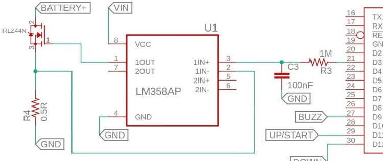
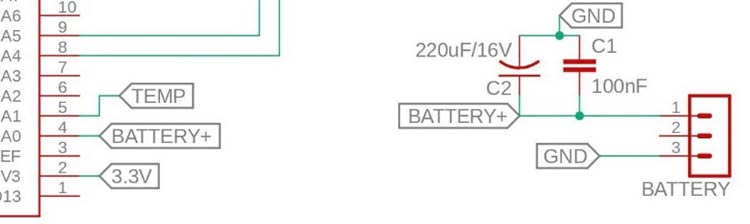
Battery Voltage Measurement Section
The battery voltage is measured by the Arduino analog input pin A0. Two capacitors C1 and C2 are used to filter out the noises coming from the constant current load circuit which can degrade the ADC conversion performance.
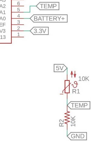
Battery Temperature Section
The battery temperature was measured using a 10K NTC thermistor. Thermistor resistance changes with temperature. As this is an NTC thermistor, when the temperature increases, resistance decreases.
By this characteristic of NTC, adding resistance in series and creating a voltage divider could effectively convert the temperature difference in terms of changes in the output voltage of this divider. The output voltage of the divider is read by Arduino analog input pin A1, we can calculate the real-time temperature of the battery.
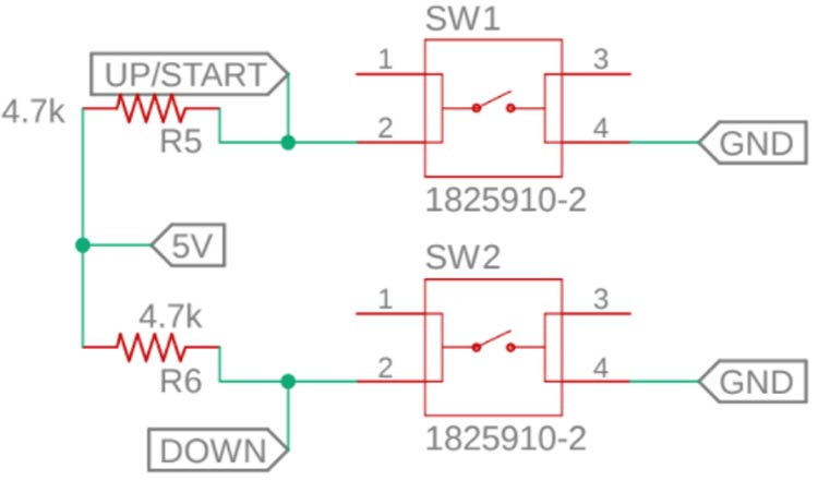
User Interface Section
The user interface circuit consists of two push buttons and a 0.96" I2C OLED display. The Up and Down push-button is to increase or decrease the PWM pulse width. R5 and R6 are pull-up resistors for the Up and Down push-buttons. The third push-button (RST) is used for resetting the Arduino.
How does the Battery Capacity Tester Work?
The theory is based on the voltage comparison of the inverting (pin-2) and the non-inverting (pin-3) inputs of the Op-Amp, configured as a unity amplifier. When you set the voltage applied to the non-inverting input by adjusting the PWM signal, the output of the Op-Amp opens the gate of MOSFET. As the MOSFET turn-on, the current runs through R1, which creates a voltage drop, that provides negative feedback to Op-Amp. It controls the MOSFET in such a way that the voltages at its inverting and non-inverting inputs are equal. So, the current through the load resistor is proportional to the voltage at the non-inverting input of the Op-Amp. The PWM signal from the Arduino is filtered by using a low pass filter circuit (R3 and C3).
Battery Capacity (mAh) = Current (I ) in mA x Time ( T ) in Hours
To calculate the battery capacity(mAh) using the above equation, we have to know the current in mA and time in Hour. The designed circuit is a constant current load circuit, so the discharge current remains constant throughout the testing period. The discharge current can be adjusted by pressing the Up and Down Button. The time duration is measured by using a timer in the Arduino code.
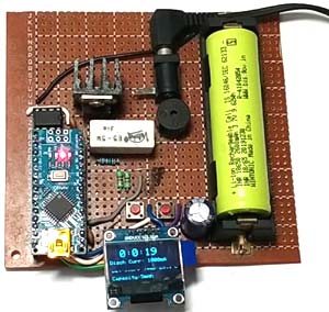
Soldering the components on Perf-board
Now as this circuit consists of a battery we decided to solder all the components on perf-board as shown below.

Programming Arduino for Battery Tester
After soldering the components on perf-board, let’s program the Arduino Nano to test the battery capacity using the time and current readings. Complete code can be found at the end of the document. Here we are explaining the complete code line by line.
So as usual start the code by including all the required library files. Here JC_Button.h library is used to read the button states and Adafruit_SSD1306.h library is used to print the readings on OLED display. Both the libraries can be installed from Arduino IDE’s library manager.
#include<JC_Button.h>
#include <Adafruit_SSD1306.h>
Then in the next lines define all the variables used in this code
int ThermistorPin = A1;
int Vo;
float R1 = 10000;
float logR2, R2, T;
float c1 = 1.009249522e-03, c2 = 2.378405444e-04, c3 = 2.019202697e-07;
The next line of code is used to set the reference voltage. The Vcc is the most important variable in this project to detect the battery voltage. To set the Vcc, first connect the Arduino with the external power source 7-12 Volt. Then measure the voltage of the Arduino 5V pin using Multimeter. Then set the value of Vcc in this code.
float Vcc = 5.04 ; // Voltage of Arduino 5V pin ( Mesured by Multimeter after connecting external 9V Supply )
const int Current [] = {0,70,100,190,350,400,500,620,700,830,910,1000};
const int PWM_RES [] = {0, 1, 2, 4, 8, 9, 12, 15, 17, 20, 22, 24};
Measuring the Voltage difference between R4, evaluate the current using the formula:
V = I X R
So, I = V/R
Let, I = 100mA/0.1A, and R4 = 0.5R
So required voltage = 0.1 x 0.5 = 0.05V
So set a PWM value to get the Voltage input Op-Amp pin 3 to achieve the voltage across R4. This is how to get a proper set of PWM to related output Current.
int ThermistorPin = A1;
int Vo;
float R1 = 10000;
float logR2, R2, T;
float c1 = 1.009249522e-03, c2 = 2.378405444e-04, c3 = 2.019202697e-07;
We can use an equation that approximates the temperature of the thermistor response curve to calculate the temperature. For example, the widely used Steinhart-Hart equation is shown below
1/T=A+B*ln(R)+C*(ln(R))^3
It can be derived using measured temperature-resistance data. We will use the simpler Beta (or B) parameter equation shown below. Though not as accurate as of the Steinhart-Hart equation, it still provides good results over a narrower temperature range.
1/T=1/T0+1/B*ln(R/R0)
The variable T is the ambient temperature in Kelvin, T0 is usually room temperature, also in Kelvin (25°C = 298.15K), B is the beta constant, R is the thermistor resistance at the ambient temperature (same as Rt above), and R0 is the thermistor resistance at temperature T0. The values for T0, B, and R0 can be found in the manufacturer's datasheet. You can calculate the value for R as described previously for Rt.
If the voltage divider source voltage and Vref are the same you don't need to know R0 or find R to calculate the temperature. Remember you can write the equation for the thermistor resistance in terms of the ratio of ADC values
R=R0*((adcMax/adcVal)-1)
then
1/T=1/T0+1/B*ln(R0*((adcMax/adcVal)-1)/R0) R0 cancels out, which leaves:
1/T=1/T0+1/B*ln((adcMax/adcVal)–1)
Take the reciprocal of the result to get the temperature in Kelvin. For example, assume a thermistor voltage divider circuit is connected to a 10 bit ADC. The beta constant for the thermistor is 3380, the thermistor resistance (R0) at 25°C is 10K ohms, and the ADC returns a value of 366.
1/T=1/298.15+1/3380*ln((1023/366)-1)
1/T=0.003527
T = 283.52K – 273.15K = 10.37°C
This further reflected on the Temperature sensing function –
void temp() {

       Vo = analogRead(ThermistorPin);
       R2 = R1 * (1023.0 / (float)Vo - 1.0);
       logR2 = log(R2);
       T = (1.0 / (c1 + c2*logR2 + c3*logR2*logR2*logR2));
       T = T - 273.15;
}
In the loop function, the button states are read properly at first. Whenever the button is pressed the current gets increased or decreased. While pressing the button for 1000ms, the time count down is started.
void loop() {
  UP_Button.read();
  Down_Button.read();
  if (UP_Button.wasReleased() && l < 11 && calc == false) {
      l=l+1;
  }
  if (Down_Button.wasReleased() && l > 0 && calc == false) {
      l=l-1;
  }
  if (UP_Button.pressedFor (1000) && calc == false) {
      analogWrite(PWM_Pin,PWM_RES[l]);
      digitalWrite(Buzzer, HIGH);
      delay(1500);
      digitalWrite(Buzzer, LOW);
      timerInterrupt();
  }
}
Testing the Battery Capacity Tester
Now as everything is connected in the place and Arduino is programmed to calculate the battery capacity, let’s connect a battery and test how it performs. All the readings like discharge current, battery capacity, etc. will be displayed on OLED display.
Well, this project can be constructed using a PCB for optimal performance and accurate results. The full working video and complete code is given below. If you have any questions or suggestions related to this project you can put them in the comment section or in our forum.
Complete Project Code
#include<JC_Button.h>
#include <Adafruit_SSD1306.h>
#define SCREEN_WIDTH 128 // OLED display width, in pixels
#define SCREEN_HEIGHT 64 // OLED display height, in pixels
// Declaration for an SSD1306 display connected to I2C (SDA, SCL pins)
#define OLED_RESET -1
Adafruit_SSD1306 display(SCREEN_WIDTH, SCREEN_HEIGHT, &Wire, OLED_RESET);
int ThermistorPin = A1;
int Vo;
float R1 = 10000;
float logR2, R2, T;
float c1 = 1.009249522e-03, c2 = 2.378405444e-04, c3 = 2.019202697e-07;
const int Current [] = {0,70,100,190,350,400,500,620,700,830,910,1000};
const int PWM_RES [] = {0, 1, 2, 4, 8, 9, 12, 15, 17, 20, 22, 24};
int l = 0;
const float Low_BAT_level = 3.4;
const byte PWM_Pin = 3;
const byte Buzzer = 9;
const int BAT_Pin = A0;
int PWM_Value = 0;
unsigned long Capacity = 0;
int ADC_Value = 0;
float Vcc = 5.04 ; // Voltage of Arduino 5V pin ( Mesured by Multimeter after connecting external 9V Supply )
float BAT_Voltage = 0;
float sample =0;
byte Hour = 0, Minute = 0, Second = 0;
bool calc = false, Done = false;
Button UP_Button(11, 25, false, true);
Button Down_Button(12, 25, false, true);
// 'Circuit-Digest-Logo', 128x64px
const unsigned char myBitmap [] PROGMEM = {
  0x00, 0x00, 0x00, 0x00, 0x00, 0x00, 0x00, 0x00, 0x00, 0x00, 0x00, 0x00, 0x00, 0x00, 0x00, 0x00,
  0x00, 0x00, 0x00, 0x00, 0x00, 0x00, 0x00, 0x00, 0x00, 0x00, 0x00, 0x00, 0x00, 0x00, 0x00, 0x00,
  0x00, 0x00, 0x00, 0x00, 0x00, 0x00, 0x00, 0x00, 0x00, 0x00, 0x00, 0x00, 0x00, 0x00, 0x00, 0x00,
  0x00, 0x00, 0x00, 0x00, 0x00, 0x00, 0x00, 0x00, 0x00, 0x00, 0x00, 0x00, 0x00, 0x00, 0x00, 0x00,
  0x00, 0x00, 0x00, 0x00, 0x00, 0x00, 0x00, 0x00, 0x00, 0x00, 0x00, 0x00, 0x00, 0x00, 0x00, 0x00,
  0x00, 0x00, 0x00, 0x00, 0x00, 0x00, 0x00, 0x00, 0x00, 0x00, 0x00, 0x00, 0x00, 0x00, 0x00, 0x00,
  0x00, 0x00, 0x00, 0x00, 0x00, 0x00, 0x00, 0x00, 0x00, 0x00, 0x00, 0x00, 0x00, 0x00, 0x00, 0x00,
  0x00, 0x00, 0x00, 0x00, 0x00, 0x00, 0x00, 0x00, 0x00, 0x00, 0x00, 0x00, 0x00, 0x00, 0x00, 0x00,
  0x00, 0x00, 0x00, 0x00, 0x00, 0x00, 0x00, 0x00, 0x00, 0x00, 0x00, 0x00, 0x00, 0x00, 0x00, 0x00,
  0x00, 0x00, 0x00, 0x00, 0x00, 0x00, 0x00, 0x00, 0x00, 0x00, 0x00, 0x00, 0x00, 0x00, 0x00, 0x00,
  0x00, 0x00, 0x00, 0x00, 0x00, 0x00, 0x00, 0x00, 0x00, 0x00, 0x00, 0x00, 0x00, 0x00, 0x00, 0x00,
  0x00, 0x00, 0x00, 0x00, 0x00, 0x00, 0x00, 0x00, 0x00, 0x00, 0x00, 0x00, 0x00, 0x00, 0x00, 0x00,
  0x00, 0x00, 0x00, 0x00, 0x00, 0x00, 0x00, 0x00, 0x00, 0x00, 0x00, 0x00, 0x00, 0x00, 0x00, 0x00,
  0x00, 0x00, 0x00, 0x00, 0x00, 0x00, 0x00, 0x00, 0x00, 0x00, 0x00, 0x00, 0x00, 0x00, 0x00, 0x00,
  0x00, 0x00, 0x00, 0x00, 0x00, 0x00, 0x00, 0x00, 0x00, 0x00, 0x00, 0x00, 0x00, 0x00, 0x00, 0x00,
  0x00, 0x00, 0x00, 0x00, 0x00, 0x00, 0x00, 0x00, 0x00, 0x00, 0x00, 0x00, 0x00, 0x00, 0x00, 0x00,
  0x00, 0x00, 0x00, 0x00, 0x00, 0x00, 0x00, 0x00, 0x00, 0x00, 0x00, 0x00, 0x00, 0x00, 0x00, 0x00,
  0x00, 0x00, 0x00, 0x00, 0x00, 0x00, 0x00, 0x00, 0x00, 0x00, 0x00, 0x00, 0x00, 0x00, 0x00, 0x00,
  0x00, 0x00, 0x00, 0x00, 0x00, 0x00, 0x00, 0x00, 0x00, 0x00, 0x00, 0x00, 0x00, 0x00, 0x00, 0x00,
  0x00, 0x00, 0x00, 0x00, 0x00, 0x00, 0x00, 0x00, 0x00, 0x00, 0x00, 0x00, 0x00, 0x00, 0x00, 0x00,
  0x00, 0x00, 0x00, 0x00, 0x00, 0x00, 0x00, 0x00, 0x00, 0x00, 0x00, 0x00, 0x00, 0x00, 0x00, 0x00,
  0x00, 0x00, 0x00, 0x00, 0x00, 0x00, 0x00, 0x00, 0x00, 0x00, 0x00, 0x00, 0x00, 0x00, 0x00, 0x00,
  0xff, 0xff, 0xff, 0xff, 0xff, 0xff, 0xff, 0xff, 0xff, 0xff, 0xff, 0xff, 0xff, 0xff, 0xff, 0xff,
  0xff, 0xff, 0xff, 0xff, 0xff, 0xff, 0xff, 0xff, 0xff, 0xff, 0xff, 0xff, 0xff, 0xff, 0xff, 0xff,
  0xff, 0xff, 0xff, 0xff, 0xff, 0xff, 0xff, 0xff, 0xff, 0xff, 0xff, 0xff, 0xff, 0xff, 0xff, 0xff,
  0xff, 0xff, 0xff, 0xff, 0xff, 0x9f, 0xff, 0xff, 0xff, 0xff, 0xff, 0xff, 0xff, 0xff, 0xff, 0xff,
  0xff, 0xbf, 0xff, 0xff, 0xff, 0x9f, 0xff, 0xff, 0xff, 0xff, 0xff, 0xff, 0xff, 0xff, 0xff, 0xff,
  0xff, 0x03, 0xff, 0xff, 0xff, 0x1f, 0xff, 0xff, 0xff, 0xff, 0xff, 0xff, 0xff, 0xff, 0xff, 0xff,
  0xf2, 0x39, 0xff, 0xff, 0xfe, 0x7f, 0xff, 0xff, 0xff, 0xff, 0xff, 0xff, 0xff, 0xff, 0xff, 0xff,
  0xe2, 0x06, 0xff, 0xf8, 0x1c, 0xff, 0xff, 0xff, 0xe7, 0xfe, 0x07, 0xef, 0xff, 0xff, 0xff, 0xff,
  0xe4, 0x21, 0xff, 0xe0, 0x19, 0xff, 0xff, 0xff, 0xe7, 0x3e, 0xf3, 0xef, 0xff, 0xff, 0xff, 0xe7,
  0xf1, 0x80, 0x7f, 0xc7, 0xff, 0xff, 0xff, 0xff, 0xff, 0x3e, 0xfd, 0xff, 0xff, 0xff, 0xff, 0xe7,
  0xc1, 0x00, 0x3f, 0x8f, 0xff, 0xff, 0xe7, 0xff, 0xff, 0x1e, 0xfe, 0xff, 0xff, 0xff, 0xff, 0xe7,
  0x82, 0x00, 0x7f, 0x9f, 0xf9, 0xc1, 0x81, 0x9e, 0x66, 0x06, 0xfe, 0xef, 0x03, 0xc1, 0xe0, 0xc1,
  0xfe, 0x3f, 0xff, 0x9f, 0xf9, 0xc3, 0x1f, 0x9e, 0x66, 0x0e, 0xfe, 0xee, 0x7b, 0xbc, 0xdf, 0xe7,
  0xc0, 0x00, 0x3f, 0x9f, 0xf9, 0xcf, 0x3f, 0x9e, 0x67, 0x3e, 0xfe, 0xee, 0xfb, 0xbe, 0xdf, 0xe7,
  0x80, 0x8f, 0xff, 0x9f, 0xf9, 0xcf, 0x3f, 0x9e, 0x67, 0x3e, 0xfe, 0xec, 0xfb, 0x00, 0xe3, 0xe7,
  0xc0, 0xd0, 0x7f, 0x8f, 0xf9, 0xcf, 0x3f, 0x9e, 0x67, 0x3e, 0xfe, 0xee, 0xfb, 0x3f, 0xfc, 0xe7,
  0xfc, 0x60, 0x7f, 0xc7, 0xf9, 0xcf, 0x3f, 0x9e, 0x67, 0x3e, 0xfc, 0xee, 0xfb, 0xbf, 0xfe, 0xe7,
  0xe3, 0x03, 0xff, 0xe0, 0x19, 0xcf, 0x01, 0x80, 0x67, 0x3e, 0xf1, 0xee, 0x7b, 0x9f, 0xfe, 0xe7,
  0xe1, 0x09, 0xff, 0xf0, 0x19, 0xcf, 0xc1, 0xc0, 0xe7, 0x3e, 0x07, 0xef, 0x03, 0xc1, 0xc0, 0xf7,
  0xf0, 0x31, 0xff, 0xff, 0xff, 0xff, 0xff, 0xff, 0xff, 0xff, 0xff, 0xff, 0xfb, 0xff, 0xff, 0xff,
  0xfc, 0x07, 0xff, 0xff, 0xff, 0xff, 0xff, 0xff, 0xff, 0xff, 0xff, 0xff, 0xfb, 0xff, 0xff, 0xff,
  0xff, 0xff, 0xff, 0xff, 0xff, 0xff, 0xff, 0xff, 0xff, 0xff, 0xff, 0xff, 0xf7, 0xff, 0xff, 0xff,
  0xff, 0xff, 0xff, 0xff, 0xff, 0xff, 0xff, 0xff, 0xff, 0xff, 0xff, 0xff, 0x0f, 0xff, 0xff, 0xff,
  0xff, 0xff, 0xff, 0xff, 0xff, 0xff, 0xff, 0xff, 0xff, 0xff, 0xff, 0xff, 0xff, 0xff, 0xff, 0xff,
  0xff, 0xff, 0xff, 0xff, 0xff, 0xff, 0xff, 0xff, 0xff, 0xff, 0xff, 0xff, 0xff, 0xff, 0xff, 0xff,
  0xff, 0xff, 0xff, 0xff, 0xff, 0xff, 0xff, 0xff, 0xff, 0xff, 0xff, 0xff, 0xff, 0xff, 0xff, 0xff,
  0x00, 0x00, 0x00, 0x00, 0x00, 0x00, 0x00, 0x00, 0x00, 0x00, 0x00, 0x00, 0x00, 0x00, 0x00, 0x00,
  0x00, 0x00, 0x00, 0x00, 0x00, 0x00, 0x00, 0x00, 0x00, 0x00, 0x00, 0x00, 0x00, 0x00, 0x00, 0x00,
  0x00, 0x00, 0x00, 0x00, 0x00, 0x00, 0x00, 0x00, 0x00, 0x00, 0x00, 0x00, 0x00, 0x00, 0x00, 0x00,
  0x00, 0x00, 0x00, 0x00, 0x00, 0x00, 0x00, 0x00, 0x00, 0x00, 0x00, 0x00, 0x00, 0x00, 0x00, 0x00,
  0x00, 0x00, 0x00, 0x00, 0x00, 0x00, 0x00, 0x00, 0x00, 0x00, 0x00, 0x00, 0x00, 0x00, 0x00, 0x00,
  0x00, 0x00, 0x00, 0x00, 0x00, 0x00, 0x00, 0x00, 0x00, 0x00, 0x00, 0x00, 0x00, 0x00, 0x00, 0x00,
  0x00, 0x00, 0x00, 0x00, 0x00, 0x00, 0x00, 0x00, 0x00, 0x00, 0x00, 0x00, 0x00, 0x00, 0x00, 0x00,
  0x00, 0x00, 0x00, 0x00, 0x00, 0x00, 0x00, 0x00, 0x00, 0x00, 0x00, 0x00, 0x00, 0x00, 0x00, 0x00,
  0x00, 0x00, 0x00, 0x00, 0x00, 0x00, 0x00, 0x00, 0x00, 0x00, 0x00, 0x00, 0x00, 0x00, 0x00, 0x00,
  0x00, 0x00, 0x00, 0x00, 0x00, 0x00, 0x00, 0x00, 0x00, 0x00, 0x00, 0x00, 0x00, 0x00, 0x00, 0x00,
  0x00, 0x00, 0x00, 0x00, 0x00, 0x00, 0x00, 0x00, 0x00, 0x00, 0x00, 0x00, 0x00, 0x00, 0x00, 0x00,
  0x00, 0x00, 0x00, 0x00, 0x00, 0x00, 0x00, 0x00, 0x00, 0x00, 0x00, 0x00, 0x00, 0x00, 0x00, 0x00,
  0x00, 0x00, 0x00, 0x00, 0x00, 0x00, 0x00, 0x00, 0x00, 0x00, 0x00, 0x00, 0x00, 0x00, 0x00, 0x00,
  0x00, 0x00, 0x00, 0x00, 0x00, 0x00, 0x00, 0x00, 0x00, 0x00, 0x00, 0x00, 0x00, 0x00, 0x00, 0x00,
  0x00, 0x00, 0x00, 0x00, 0x00, 0x00, 0x00, 0x00, 0x00, 0x00, 0x00, 0x00, 0x00, 0x00, 0x00, 0x00,
  0x00, 0x00, 0x00, 0x00, 0x00, 0x00, 0x00, 0x00, 0x00, 0x00, 0x00, 0x00, 0x00, 0x00, 0x00, 0x00,
  0x00, 0x00, 0x00, 0x00, 0x00, 0x00, 0x00, 0x00, 0x00, 0x00, 0x00, 0x00, 0x00, 0x00, 0x00, 0x00,
  0x00, 0x00, 0x00, 0x00, 0x00, 0x00, 0x00, 0x00, 0x00, 0x00, 0x00, 0x00, 0x00, 0x00, 0x00, 0x00,
  0x00, 0x00, 0x00, 0x00, 0x00, 0x00, 0x00, 0x00, 0x00, 0x00, 0x00, 0x00, 0x00, 0x00, 0x00, 0x00,
  0x00, 0x00, 0x00, 0x00, 0x00, 0x00, 0x00, 0x00, 0x00, 0x00, 0x00, 0x00, 0x00, 0x00, 0x00, 0x00,
  0x00, 0x00, 0x00, 0x00, 0x00, 0x00, 0x00, 0x00, 0x00, 0x00, 0x00, 0x00, 0x00, 0x00, 0x00, 0x00,
  0x00, 0x00, 0x00, 0x00, 0x00, 0x00, 0x00, 0x00, 0x00, 0x00, 0x00, 0x00, 0x00, 0x00, 0x00, 0x00
};
// Array of all bitmaps for convenience. (Total bytes used to store images in PROGMEM = 1040)
void setup () {
Serial.begin(9600);
pinMode(PWM_Pin, OUTPUT);
pinMode(Buzzer, OUTPUT);
analogWrite(PWM_Pin, PWM_RES[l]);
UP_Button.begin();
Down_Button.begin();
display.begin(SSD1306_SWITCHCAPVCC, 0x3C);
display.clearDisplay();
display.drawBitmap(0, 0, myBitmap, 128, 64, WHITE);
display.display();
delay(3500);
display.setTextColor(WHITE);
display.clearDisplay();
display.setTextSize(2);
display.setCursor(2,15);
display.print("Adj Curr:");
display.setCursor(2,40);
display.print("UP   Down:");
display.print("0");
display.display();
}
//************************* End of Setup function *******************************
void loop() {
  UP_Button.read();
  Down_Button.read();
if (UP_Button.wasReleased() && l < 11 && calc == false)
 {
  l=l+1;
  display.clearDisplay();
  display.setCursor(2,25);
  display.print("Curr:");
  display.print(String(Current[l])+"mA");
  display.display();
 }
if (Down_Button.wasReleased() && l > 0 && calc == false)
{
  l=l-1;
  display.clearDisplay();
  display.setCursor(2,25);
  display.print("Curr:");
  display.print(String(Current[l])+"mA");
  display.display();
}
if (UP_Button.pressedFor (1000) && calc == false)
{
  analogWrite(PWM_Pin,PWM_RES[l]);
  digitalWrite(Buzzer, HIGH);
  delay(1500);
  digitalWrite(Buzzer, LOW);
  display.clearDisplay();
  timerInterrupt();
  }
}
//************************* End of Loop function *******************************
void timerInterrupt(){
  calc = true;
  while (Done == false)  {
     Second ++;
    if (Second == 60)  {
      Second = 0;
      Minute ++;
    }
    if (Minute == 60)  {
      Minute = 0;
      Hour ++;
    }
 //************ Measuring Battery Voltage ***********
for(int i=0;i< 100;i++)
  {
   sample=sample+analogRead(BAT_Pin); //read the Battery voltage
   delay (2);
  }
  sample=sample/100;
  BAT_Voltage = sample * (Vcc/ 1024.0);
  temp();
 //*********************************************
    display.clearDisplay();
    display.setTextSize(2);
    display.setCursor(20,5);
    display.print(String(Hour) + ":" + String(Minute) + ":" + String(Second));
    display.setTextSize(1);
    display.setCursor(0,25);
    display.print("Disch Curr: ");
    display.print(String(Current[l])+"mA");
    display.setCursor(2,40);
    display.print("Bat:" + String(BAT_Voltage)+"V" );
    display.setCursor(63,40);
    display.print("Temp:"+String(T,1));
    display.setCursor(116,35);
    display.print(".");
    display.setCursor(122,40);
    display.print("C");
    Capacity =  (Hour * 3600) + (Minute * 60) + Second;
    Capacity = (Capacity * Current[l]) / 3600;
    display.setCursor(2, 55);
    display.print("Capacity:" + String(Capacity) + "mAh");
    display.display();
    if (BAT_Voltage < Low_BAT_level)
    {
      Capacity =  (Hour * 3600) + (Minute * 60) + Second;
      Capacity = (Capacity * Current[l]) / 3600;
      display.clearDisplay();
      display.setTextSize(2);
      display.setCursor(2,15);
      display.print("Capacity:");
      display.setCursor(2,40);
      display.print(String(Capacity) + "mAh");
      display.display();
      Done = true;
      l = 0;
      analogWrite(PWM_Pin, PWM_RES[l]);
      digitalWrite(Buzzer, HIGH);
      delay(100);
      digitalWrite(Buzzer, LOW);
      delay(100);
      digitalWrite(Buzzer, HIGH);
      delay(100);
      digitalWrite(Buzzer, LOW);
      delay(100);
    }
       delay(1000);
  }
}
    void temp()
    {
       Vo = analogRead(ThermistorPin);
       R2 = R1 * (1023.0 / (float)Vo - 1.0);
       logR2 = log(R2);
       T = (1.0 / (c1 + c2*logR2 + c3*logR2*logR2*logR2));
       T = T - 273.15;
}Comments
That's marvelous. This project is similar to what I want to know. (AC over load protection using arduino).
Please, you should make it visible for us because you are the guru.
I looked at this project some time like a year ago and started it but didn't finish it for a reason I forget, maybe for some of the parts, maybe because I was having issues getting the code going. Anyway, I'm back looking at it too hopefully finish it and I see the OLED is shown powered by 3.3v. I need to go back to the circuit board I have so far and re familiarize with it, I do know the OLED's I have are some I got for other projects and IRC those are 5Vcc to the OLED. Some of those OLED's I have have been modified because a SWR project I have been trying to get working indicated there was an issue with the charge pump section of the OLED was generating 50hz buzzing in the radios. The mod was to remove the 2 charge pump caps and bypass the Vcc to a 9v source. I did save those caps and would have find them in the container I put them in, just in case I decided to re solder them on an OLED board. Also there are a couple of OLED's I have with different pinouts for the + & - which is no big deal. All that aside, I just wondered if the OLED's would work properly on either 3.3v or 5v?

Rebonjour, début 1970 j'ai acheté en kit cette montre : Bulova accutron spaceview. A l'époque elle était alimentée par une pile bouton de 1.35 V mais l'UE a interdit la fabrication de cette pile avec un composant au mercure (Hg). La plupart des piles ont une tension de 1.55 V. Cette différence de tension (0.20V) fait que la montre est déréglée: elle avance beaucoup et je n'ai plus la précision de deux secondes / jour.
Pouvez-vous m'aider ?
Merci pour votre collaboration.