
In this tutorial, we are going to build an easy and cheap Pedometer using ATtiny85 IC, MPU6050 Accelerometer & Gyroscope, and OLED Display Module. This simple Arduino based step counter is powered by a 3V coin cell, making it easy to carry when you go out for a walk or jog. It also requires very few components to build and the code is also relatively simple. The program in this project uses the MPU6050 to measure the magnitude of the acceleration along the 3 axis (X, Y, and Z). Then it calculates the difference of the acceleration magnitude between the previous and current values. If the difference is greater than a certain threshold (For walking greater than 6 and for running greater than 10), then it increases the step count accordingly. The total steps taken are then displayed on OLED Display.
To build this portable step counter on a PCB, we have fabricated our PCB boards from PCBWay and we will assemble and test the same in this project. If you want to add more features, you can also add a Heartbeat monitor to this setup and we have also previously built an Arduino accelerometer step counter using ADXL335, check them out if you are interested.
Components Required
To build this pedometer using Arduino, you will need the following components.
- Attiny85 IC
- MPU6050
- OLED Display Module
- 2× Push Buttons
- 5× 10KΩ Resistors (SMD)
MPU6050 Sensor Module – A Brief Introduction
MPU6050 is based on Micro-Mechanical Systems (MEMS) technology. This sensor has a 3-axis accelerometer, a 3-axis gyroscope, and an in-built temperature sensor. It can be used to measure parameters like Acceleration, Velocity, Orientation, Displacement, etc. We have previously interfaced MPU6050 with Arduino and Raspberry pi and also built a few projects using it like- Self Balancing robot, Arduino Digital Protractor, and Arduino Inclinometer.
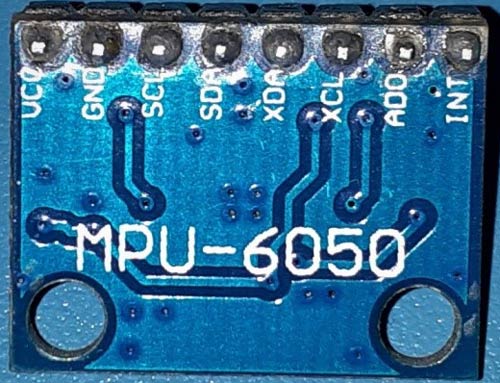
The MPU6050 module is small in size and has low power consumption, high repetition, high shock tolerance, and low user price points. The MPU6050 comes with an I2C bus and Auxiliary I2C bus interface and can easily interfere with other sensors such as magnetometers and microcontrollers.
Attiny85 Step Counter Circuit Diagram
The schematic for the MPU6050 Step Counter is given below:

The above image shows the circuit diagram for interfacing MPU6050 and OLED Display with Attiny85 IC. The interface between MPU6050, OLED Display, and Arduino must be implemented using I2C Protocol. Hence, the SCLPin (PB2) of the ATtiny85 is connected to the SCLPin of the MPU6050 and OLED Display respectively. Similarly, the SDAPin (PB0) of the ATtiny85 is connected to the SDAPin of the MPU6050 and OLED Display. Two pushbuttons are also connected to the PB3 & PB4 pin of ATtiny85 IC. These buttons can be used to scroll the text or change the text on display.
Note: Follow our previous tutorial Programming ATtiny85 IC directly through USB using Digispark Bootloader to program the ATtiny85 IC through USB and Digispark Boot-loader.
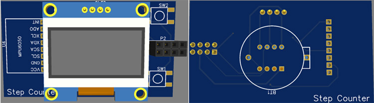
Fabricating PCB for Attiny85 Step Counter
The schematic is done, and we can proceed with laying out the PCB. You can design the PCB using any PCB software of your choice. We have used EasyEDA to fabricate PCB for this project.
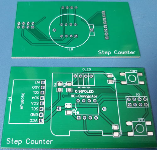
Below are the 3D model views of the top layer and bottom layer of the Step Counter PCB:
The PCB layout for the above circuit is also available for download as Gerber from the link given below:
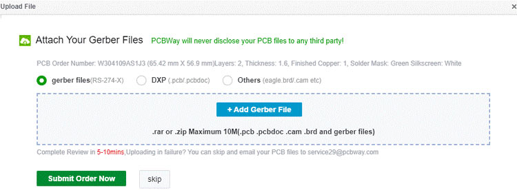
Ordering PCB from PCBWay
Now after finalizing the design, you can proceed with ordering the PCB:
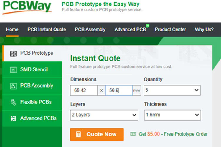
Step 1: Get into https://www.pcbway.com/, sign up if this is your first time. Then, in the PCB Prototype tab, enter the dimensions of your PCB, the number of layers, and the number of PCB you require.
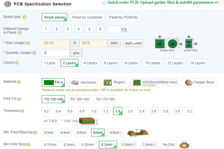
Step 2: Proceed by clicking on the ‘Quote Now’ button. You will be taken to a page where to set a few additional parameters like the Board type, Layers, Material for PCB, Thickness, and More, most of them are selected by default, if you are opting for any specific parameters, you can select it in here.
Step 3: The final step is to upload the Gerber file and proceed with the payment. To make sure the process is smooth, PCBWAY verifies if your Gerber file is valid before proceeding with the payment. This way, you can sure that your PCB is fabrication friendly and will reach you as committed.
Assembling the ATtiny85 Step Counter PCB
After a few days, we received our PCB in a neat package and the PCB quality was good as always. The top layer and the bottom layer of the board are shown below:
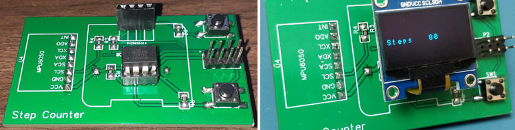
After making sure the tracks and footprints were correct. I proceeded with assembling the PCB. The completely soldered board looks like the below:
ATtiny85 Step Counter Code Explanation
The complete Arduino step counter code is given at the end of the document. Here we are explaining some important parts of the code.
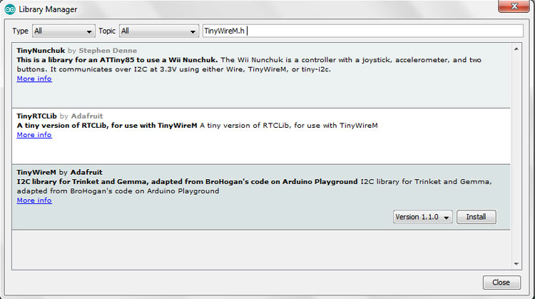
The code uses the TinyWireM.h&TinyOzOLED.h libraries. The TinyWireM library can be downloaded from the Library Manager in the Arduino IDE and install from there. For that, open the Arduino IDE and go to Sketch < Include Library < Manage Libraries. Now search for TinyWireM.h and install the TinyWireM library by Adafruit.
While the TinyOzOLED.h library can be downloaded from the given links.
After installing the libraries to Arduino IDE, start the code by including the needed libraries files.
#include "TinyWireM.h"
#include "TinyOzOLED.h"
After including the libraries, define the variables to store the Accelerometer readings.
intaccelX, accelY, accelZ;
Inside thesetup() loop, initialize the wire library and reset the sensor through the power management register also initialize the I2C communication for OLED Display. Then in the next lines set the display orientation and enter the register address for accelerometer and gyroscope values.
TinyWireM.begin();
OzOled.init();
OzOled.clearDisplay();
OzOled.setNormalDisplay();
OzOled.sendCommand(0xA1);
OzOled.sendCommand(0xC8);
TinyWireM.beginTransmission(mpu);
TinyWireM.write(0x6B);
TinyWireM.write(0b00000000);
TinyWireM.write(0x1B);
In the getAccel() function, start by reading the accelerometer data. The data for each axis is stored in two bytes (Upper & Lower) or registers. In order to read them all, start with the first register, and using the requiestFrom() function, we request to read all 6 registers for the X, Y, and Z axes. Then we read the data from each register, and because the outputs are two’s complement, combine them appropriately to get the complete accelerometer values.
voidgetAccel() {
TinyWireM.beginTransmission(mpu);
TinyWireM.write(0x3B);
TinyWireM.endTransmission();
TinyWireM.requestFrom(mpu, 6);
accelX = TinyWireM.read() << 8|TinyWireM.read();
accelY = TinyWireM.read() << 8|TinyWireM.read();
accelZ = TinyWireM.read() << 8|TinyWireM.read();
}
Now inside the loop function, first read the X, Y, and Z-axis values and after getting the 3-axis values, calculate the total acceleration vector by taking the square root of X, Y, and Z-axis values. Then calculate the difference between the current vector and the previous vector and if the difference is greater than 6, then increase the step count.
getAccel();
vector = sqrt( (accelX * accelX) + (accelY * accelY) + (accelZ * accelZ) );
totalvector = vector - vectorprevious;
if (totalvector> 6){
  Steps++;
}
OzOled.printString("Steps", 0, 4);
OzOled.printNumber(Steps, 0, 8, 4);
vectorprevious = vector;
delay(600);
Let’s take our Arduino Step Counter for a Walk
Once you finished assembling the PCB, connect the ATtiny85 to the programmer board, and upload the code. Now take the step counter setup in your hands and start walking step by step, it should display the number of steps on OLED. Sometimes it increases the number of steps when the setup vibrates very rapidly or very slowly.
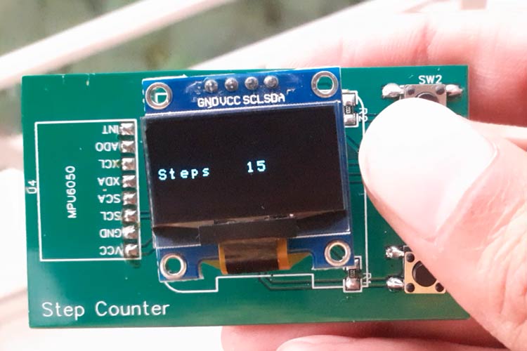
This is how you can build your own Step Counter using the ATtiny85 and MPU6050. The complete working of the project can also be found in the video linked below. Hope you enjoyed the project and found it interesting to build your own. If you have any questions, please leave them in the comment section below.
Complete Project Code
#include "TinyWireM.h"

#include "TinyOzOLED.h"

int accelX, accelY, accelZ;

char mpu = 0x68;

float vectorprevious;

float vector;

float totalvector;

int Steps = 0;

void setup() {

  TinyWireM.begin();

  OzOled.init();

  OzOled.clearDisplay();

  OzOled.setNormalDisplay();

  OzOled.sendCommand(0xA1);        // set Orientation

  OzOled.sendCommand(0xC8);

  TinyWireM.beginTransmission(mpu);

  TinyWireM.write(0x6B); //  Power setting address

  TinyWireM.write(0b00000000); // Disable sleep mode (just in case)

  TinyWireM.endTransmission();

  TinyWireM.beginTransmission(mpu);

  TinyWireM.write(0x1B); // Config register for Gyro

  TinyWireM.write(0x00000000); // 250° per second range (default)

  TinyWireM.endTransmission();

  TinyWireM.beginTransmission(mpu); //I2C address of the MPU

  TinyWireM.write(0x1C); // Accelerometer config register

  TinyWireM.write(0b00000000); // 2g range +/- (default)

  TinyWireM.endTransmission();

}

void loop() {

 getAccel();

 vector = sqrt( (accelX * accelX) + (accelY * accelY) + (accelZ * accelZ) );

 //OzOled.printString("Vec:", 0, 2);

 //OzOled.printNumber(vector, 0, 5, 2);

 totalvector = vector - vectorprevious;

 //OzOled.printString("Pre:", 0, 4);

 //OzOled.printNumber(vectorprevious, 0, 5, 4);

 //OzOled.printString("Diff:", 0, 6);

 //OzOled.printNumber(totalvector, 0, 5, 6);

if (totalvector > 6){

  Steps++;

}

//String Step_count = String(Steps);

//char data[2];

//Step_count.toCharArray(data, 2);

//OzOled.printBigNumber(data, 6, 2, 3);

OzOled.printString("Steps", 0, 4);

OzOled.printNumber(Steps, 0, 8, 4);

vectorprevious = vector;

delay(600);

//OzOled.clearDisplay();

}

void getAccel() {

  TinyWireM.beginTransmission(mpu); //I2C address of the MPU

  TinyWireM.write(0x3B); //  Acceleration data register

  TinyWireM.endTransmission();

  TinyWireM.requestFrom(mpu, 6); // Get 6 bytes, 2 for each DoF

  accelX = TinyWireM.read() << 8|TinyWireM.read();

  accelY = TinyWireM.read() << 8|TinyWireM.read();

  accelZ = TinyWireM.read() << 8|TinyWireM.read();

 // OzOled.printNumber(accelX, 0, 0, 0);

 // OzOled.printNumber(accelY, 0, 0, 2);

  //OzOled.printNumber(accelZ, 0, 0, 4);

}
Comments
Great!
how to calculate the distance by the steps please?
Thanks
Adam
Qiao Xiaolinglong, thank you for sharing
I am very grateful to the author. It is a very practical wearable device. I watched your video and only one line of text was displayed. I will change the OLED display to 128*32. I am also redrawing the PCB Layout. In addition, I am drawing a 3D printing diagram. The casing is installed in the circuit. I want to use it for my family. Don’t worry, I will not use it for commercial purposes, and I will not publish this project.

Sorry, no link for download Gerber file for ATtiny85 Step Counter