

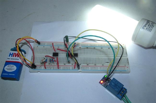
Have you ever feel a shock by touching the switch? It does not generally happen but sometimes physical contact with switches may be dangerous. But what if the switch gets wireless and you don’t have to press any button at all for switching on or off your home appliances. So today we are building a Simple Wireless Switch Circuit in which there is no need of physical contact with the switch, just one has to take his hand over the switch and it turns ON/OFF the light.
In this project, we are going to show you how to make a wireless circuit using LDR, LM741op-amp IC and 4017 decade counter IC. When you take your hand over the LDR first time, the light will turn on and when you take your hand over the LDR second time the light will turn off. We know that resistance of LDR decreases when light falls on it, so when we cover the LDR with something its resistance will increase and this will affect the Voltage at LDR. This change in voltage is sensed by Op-amp 741 and this will in turn control IC 4017 output which is connected to the AC light through Relay Module. So each time we cover the LDR with our hand, it will either switch on or Off the AC load. Working is explained further below in this article.

Material Required
- Op-amp IC LM741
- 4017 Decade counter IC
- 5v Relay module
- LDR (Light Dependent Resistor)
- Bulb
- Potentiometer (10k)
- Resistor (10k)
- Capacitor (22uf)
- Connecting wires
- Battery 9v
Circuit Diagram

OP-amp IC LM741
LM741 operational amplifier is a DC-coupled high gain electronic voltage amplifier. It’s a small chip having 8 pins. An operational amplifier IC is used as a comparator which compares the two signal, the inverting and non-inverting signal. In Op-amp IC 741 PIN2 is an inverting input terminal and PIN3 is non-inverting input terminal. The output pin of this IC is PIN6. The main function of this IC is to do the mathematical operation in various circuits.
When the voltage at non-inverting input (+) is higher than the voltage at inverting input (-), then the output of the comparator is High. And if the voltage of inverting input (-) is Higher than the non-inverting end (+), then the output is LOW. In this Wireless Switch Circuit, LM741 is used to provide the Low to high Clock pulse to IC 4017, for each time when one passes a hand over the LDR. Learn more about Op-amp 741 here.
Pin diagram of LM741
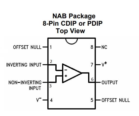
Pin Configuration of LM741
|
PIN NO. |
PIN Description |
|
1 |
Offset null |
|
2 |
Inverting (-) input terminal |
|
3 |
non-inverting (+) input terminal |
|
4 |
negative voltage supply (-VCC) |
|
5 |
offset null |
|
6 |
Output voltage pin |
|
7 |
positive voltage supply (+VCC) |
|
8 |
not connected |
Decade Counter IC 4017
4017 IC is a CMOS decade counter chip. It can produce output at the 10 pins (Q0 – Q9) sequentially, means it produces output one by one at the 10 output pins. This output is controlled by a LOW to HIGH clock pulse at PIN 14 (positive edge triggering). At first, output at Q0 (PIN 3) is HIGH, then with each clock pulse, output advance to the next PIN. Like one clock pulse makes the Q0 LOW and Q1 HIGH, and then the next clock pulse makes the Q1 LOW and Q2 HIGH, and so on. After the Q9, it will start from the Q0 again. So it creates sequential ON and OFF of all the 10 OUTPUT PINs.
In this Wireless Switch, we have used 4017 IC to latch the output to one pin when we pass the hand over LDR. Go through CD4017 circuits to learn more about this IC. And here is one simple application of Toggle switch to understand the working of 4017 to latch the output.
Pin diagram
Pin configuration of IC 4017
|
PIN NO. |
PIN Name |
PIN Description |
|
1 |
Q5 |
Output 5: Goes high in 5 clock pulse |
|
2 |
Q1 |
Output 1: Goes high in 1 clock pulse |
|
3 |
Q0 |
Output 0: Goes high at the beginning – 0 clock pulse |
|
4 |
Q2 |
Output 2: Goes high in 2 clock pulse |
|
5 |
Q6 |
Output 6: Goes high in 6 clock pulse |
|
6 |
Q7 |
Output 7: Goes high in 7clock pulse |
|
7 |
Q3 |
Output 3: Goes high in 3 clock pulse |
|
8 |
GND |
Ground PIN |
|
9 |
Q8 |
Output 8: Goes high in 8 clock pulse |
|
10 |
Q4 |
Output 4: Goes high in 4 clock pulse |
|
11 |
Q9 |
Output 9: Goes high in 9 clock pulse |
|
12 |
CO –Carry out |
Used to cascade another 4017 IC to makes it count up to 20, it is divide by 10 output PIN |
|
13 |
CLOCK inhibit |
Clock enable pin, should be kept LOW, keeping HIGH will freeze the output. |
|
14 |
CLOCK |
Clock input, for sequentially HIGH the output pins from PIN 3 TO PIN 11 |
|
15 |
RESET |
Active high pin, should be LOW for normal operation, setting HIGH will reset the IC (only Pin 3 remain HIGH) |
|
16 |
VDD |
Power supply PIN (5-12v) |
How Wireless Switch Circuit works?
Initially AC light will remain in ON condition as we have connected Relay to Q0 pin of 4017, and Q0 will be high by default in 4017 IC. Now when someone firstly passes the hand over the LDR or cover it with something then its resistance gets increased and according to Voltage Divider Rule, the voltage at Pin3 of LM741 becomes higher than Pin2, and that makes the output Pin 6 of op-amp 741 HIGH. The output of Op-amp is connected to the Clock PIN 14 of Decade counter IC 4017. As the output of OP-amp become HIGH, it gives a LOW to HIGH clock pulse to 4017 IC, which makes the output PIN3 (or Q0) of IC 4017 Low and output Pin 2 (or Q10) high, which turns off the Light connected at Q0. Now the light remains in OFF state until the next clock pulse, which will be generated when we again put the hand over LDR.
The output of LM741 remains high only till we cover the light over LDR, as soon as we remove the hand, output Pin 6 of LM741 becomes low again. But this does not affect the latched output of 4017 as IC 4017 only shifts its output to the next pin when it recieve Low to high pulse. So it won’t be affected with High to low pulse, generated when the output of LM741 goes high to low.
Now when we again pass our hand over the LDR, the op-amp output again goes High and IC 4017 again receives a Low to High clock pulse which turns the Q1 from HIGH to LOW and makes the Q2 (Pin 4) high. Now here is the trick, we have fed the Q2's high output to the reset pin 15 of IC4017, which resets the IC and put the IC in default mode where Q0 will be high. So again Light will get turn on with Q0 high.
To prevent it from misbehaving or remove error in counting pulse because of bounding effect, we have used RC circuit using the capacitor of 22uf and 10k resistor at Clock PIN 14 of 4017 IC, which helps it to count only one pulse on each time hand passes over the LDR.
Comments
i would like to clarify that what is the ac supply provided as input for the bulb.to be exact how much volt?is it 230v or 220v ,should it be directly given from the ac supply to the bulb?.can the circuit be directly implemented or is there any modifications need to be done?
Please what if i need to connect one or more ac bulbs (3 20watts =60watts in total) do I need relays for individual bulb, how do I go about it and what is the main importance of the battery with LDR? Can the size if the battery be increased based on the total ac bulb load? Hopefully I can get a quick response from someone who understands the whole circuit. Thanks
Assuming that you are connecting the loads in series, you do not need to use separate relays. just increase the power rating of the relay to match the current of your AC loads.
The LDR is the sensor and the battery powers it. You can use high Ah battery if you want it to run for a long time without any recharge
are the resisitors used only 10 k ohms?

What happens in a dark room at night. I cant see how waving your hand across the LDR would turn the light on and off if the ambient light in the room is dark all the time. would this circuit work in these conditions if you replaced the LDR with some kind of proximity detector, or perhaps even a Motion detector. It seems to me that as your circuit stands at the moment, it will only work in daylight so you can create a dark situation by covering the LDR to make the circuit switch, and then uncovering the LDR to make it switch again. A proximity switch and a motion detector dont care what level the ambient light conditions are.