

We have previously built 3x3x3 LED Cube using Arduino and Raspberry Pi. 3x3x3 LED Cube is generally build using some microcontroller, but in this session we are going to make a 3*3*3 LED CUBE without any microcontroller. Here we will use 555 timer IC and CD4020 binary counter setup to control the LED Cube.
Normally for controlling an LED CUBE, we use microcontroller and programming for getting different patterns. But for beginners it’s a complex process, so here we are using the combination of 555 Timer and CD4020 IC which is best suited for beginners. Although with this circuit we can only get one pattern, but this is the best way to get familiar with LED Cubes and their working. Learn more about 555 Timer IC by checking more 555 based circuits here.
There are many types of cubes that can be designed. The simplest one is 3x3x3 LED cube. This 3*3*3 LED CUBE is made up of 27 LEDs (Light Emitting Diodes), these LEDs are arranged in rows and columns forming a cube. Similarly we can make LED cube of 4*4*4, 5*5*5 and and higher no. of LEDs. For 4*4*4 LED cube the work almost triples because you need to do work for 64 LEDs. With each higher number, the work almost doubles or triples. But every cube more or less works on the same way.
3x3x3 LED CUBE by 555 timer is simplest because there are some advantages to this design like,
- For this cube you need not worry about power consumption or dissipation.
- Low Power supply demand.
- We don’t need any switching electronics like transistors for this cube.
- We need lesser logic terminals so we don’t need shift registers or anything like that.
- No programming needed.
- No need for complex circuitry
- Basic circuit knowledge is enough to design this project.
Components Required:
- 1KΩ resisters (10 pieces)
- 27 LEDs
- 555 Timer IC
- CD4020 Binary counter IC
- 10K Pot
- 10uF Capacitor
- 5v Power supply
- Soldering tools for building LED Cube
Circuit and Working Explanation:
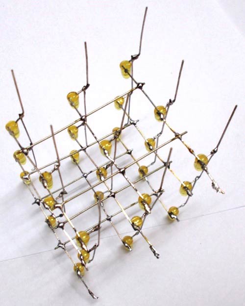
Here we have used the same LED cube which we have previously used with Raspberry Pi, and the building of this LED Cube is explained earlier in that project. Please check below two projects to properly build the LED cube by soldering the 27 LEDs in particular order:
Once everything is done you will have a cube like this one,
The Circuit Diagram of 3x3x3 LED cube using 555 Timer is shown in below figure.

As shown in picture, we have a total of 12 pins from the CUBE. Over which 9 Pins are Common Positive and 3 pins are Common Negative Terminals. Remember each column represents a positive terminal and each layer (row) represents a negative terminal.
Since we are only controlling the LED CUBE by CD4020 counter there will be no controlling needed at negative terminals. So we have grounded all three common negatives as shown in the circuit diagram. With this we will have 9 positive terminals from 9 columns of LED cube.
Now for this circuit, we first need to design a Square Wave Generator or Astable Multivibrator by using NE555 timer IC as shown in the circuit below:
Here 555 chip generates square wave for the LED to toggle between ON and OFF. The potentiometer here is to adjust the frequency of blinking.
We will feed this square wave output to the binary counter chip. Binary counter counts the clock pulses and the number of pulses counted is given by the counter through Q0-Q13 pins. We will connect these counter output pins to the LED CUBE columns according to circuit diagram. So every time count increases the output port logic changes and with this LED CUBE pattern changes.
So in nutshell, 555 timer generates clock pulses, counter counts the clock pulses and makes its output pins high accordingly and finally LED CUBE pattern changes depending on output of CD4020. That’s how the 3*3*3 LED CUBE by 555 timer-CD4020 counter pair works.
**Make sure the Master Reset of CD4020 is grounded. If it’s left alone the cube might not work.
Comments
Ur tutorial is useful nd tnq u sir......
Write about how the mobile camera working nd circiit tutorial plzz....
superb project

nice