

We have created a series of Raspberry Pi Tutorials, in which we have covered Interfacing of Raspberry Pi with all the basic components like LED, LCD, button, DC motor, Servo Motor, Stepper Motor, ADC, shift Register, etc. We have also published some simple Raspberry Pi projects for beginners, along with some good IoT projects. Today, in this session, we are going to make a 3x3x3 LED CUBE and control it by Raspberry Pi to get different patterns using the Python Programming. We have previously build the same 3x3x3 LED Cube with Arduino Uno.
A typical 3*3*3 LED cube connected to Raspberry Pi is shown in the image above. This LED CUBE is made of 27 Light Emitting Diodes, these 27 LEDs are arranged in rows and columns to form a cube. Hence the name is LED CUBE.
There are many types of cubes that can be designed. The simplest one of them is 3*3*3 LED cube. For 4*4*4 LED CUBE, the work is almost triple times because we need to do work for 64 LED. With each higher number the work almost doubles or triples. But every cube more or less works on the same way. For a beginner, 3*3*3 LED cube is the simplest LED CUBE and also there are some advantages of 3x3x3 LED Cube over other higher Cubes like,
- For this cube you need not worry about power consumption or dissipation.
- Power supply demand is less.
- We don’t need any switching electronics for this cube.
- We need lesser logic terminals so we don’t need shift registers or anything like that.
- Best suited for +3.3v logic operated electronics like Raspberry Pi.
Components Required:
Here we are using Raspberry Pi 2 Model B with Raspbian Jessie OS. All the basic Hardware and Software requirements are previously discussed, you can look it up in the Raspberry Pi Introduction and Raspberry PI LED Blinking for getting started, other than that we need:
- Raspberry Pi 2 B (any model)
- 220Ω resisters (3 pieces)
- 27 LEDs
- Soldering tools for building LED Cube
Building 3x3x3 LED Cube:
We have previously discussed the building of 3*3*3 LED cube in detail in this article: 3x3x3 LED Cube with Arduino. You should check this one for learning how to solder LEDs for forming LED Cube. Here we are mentioning 9 Common positive terminals (columns) and 3 common negative terminals (Negative Rows or layers) in LED Cube. Each column represents a positive terminal and each layer represents a negative terminal.
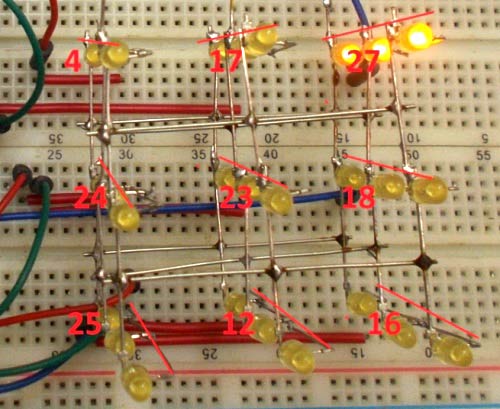
We can see 9 Common Positive Terminals from the Top View as numbered in the below picture, we have numbered them as per the GPIO pin no of Raspberry Pi, on which these positive terminals are connected.
9 Common Positive Terminals: 4, 17, 27, 24, 23, 18, 25, 12, 16
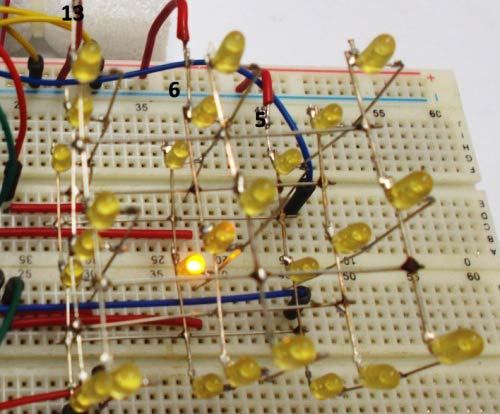
And the 3 Common Negative Terminals can be seen from Front View as numbered in the below Picture:
Top Layer common negative pin: 13
Middle Layer common negative pin: 6
Bottom Layer common negative pin: 5
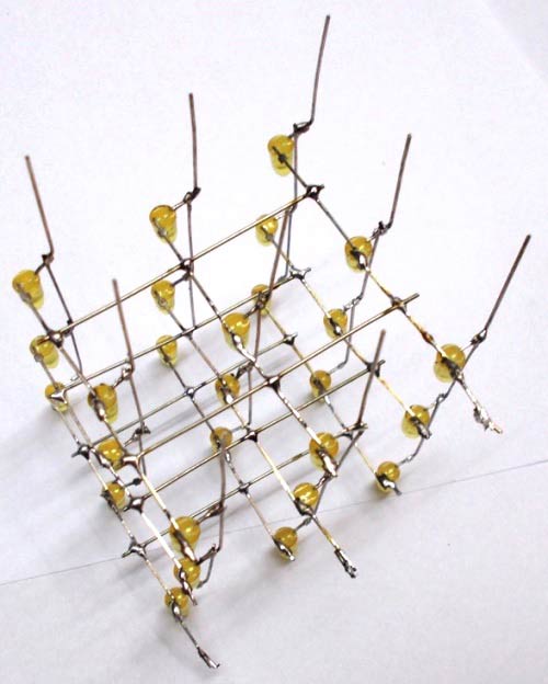
Once everything is done you will have a cube like this one. Also check the Video given in the end.
Circuit Diagram and Explanation:
Connections between Raspberry Pi and LED Cube are shown in below Circuit Diagram:

As shown in picture, we have a total of 12 pins from Cube, over which NINE are Common Positive and THREE are Common Negative Pins. Remember each column represents a positive terminal and each layer represents a negative terminal.
Now we will connect these 12 pins to Raspberry Pi exactly as given in the circuit diagram. Once we have connected the terminals it’s time to write the PYTHON program.
You can check the Python program below to generate the pattern shown in the Demo Video below.
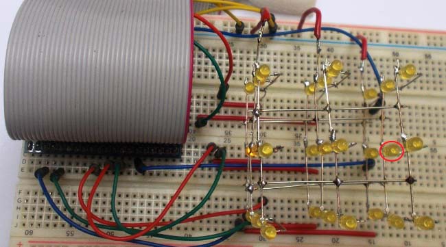
Say, we want to turn on LED on the middle layer as indicated in below picture (red circled), then we need to power the GPIO18 pin and ground the GPIO6 pin. This goes for every LED in the cube.
We have written couple of loop programs in PYTHON to make simple flashes. Program is well explained through the comments. If you want more patterns you can simple add more patterns in to the program.
Complete Project Code
#working
import RPi.GPIO as IO  #calling for header file which helps in using GPIO’s of PI
import time            #calling for time to provide delays in program
IO.setwarnings(False)  #do not show any warnings
x=1
y=1
z=0
IO.setmode (IO.BCM)
IO.setup(4,IO.OUT)   #initialize GPIO4 as an output
IO.setup(17,IO.OUT)  #initialize GPIO17 as an output
IO.setup(27,IO.OUT)  #initialize GPIO27 as an output
IO.setup(24,IO.OUT)
IO.setup(23,IO.OUT)
IO.setup(18,IO.OUT)
IO.setup(25,IO.OUT)
IO.setup(12,IO.OUT)
IO.setup(16,IO.OUT)
IO.setup(5,IO.OUT)
IO.setup(6,IO.OUT)
IO.setup(13,IO.OUT)
columns = [4,17,27,24,23,18,25,12,16]  #GPIO pins of columns in order
rows =[5,6,13]  #GPIO pins of rows in order
random = [4,24,25,17,23,12,27,18,16]   #GPIO pins of columns in random
for z in range (3):
    IO.output(rows[z],1)      #pulling up the rows
for z in range (9):
    IO.output(columns[z],0)   #pulling down the columns
while 1:
    for y in range (3):       #execute the loop 3 times incrementing y value from zero to three
        IO.output(rows[y],0)  #pull down the rows pointed by 'y'
        for x in range (9):   #execute the loop 9 times incrementing x value from zero to eight
            IO.output(columns[x],1) #pull up the columns pointed by 'x'
            time.sleep(0.1)         #sleep for 100ms
            IO.output(columns[x],0) #pull down the columns after 100ms
        IO.output(rows[y],1)        #pull up the row after 100ms
    for y in range (3):
        IO.output(rows[2-y],0)
        for x in range (9):
            IO.output(columns[8-x],1)
            time.sleep(0.1)
            IO.output(columns[8-x],0)
        IO.output(rows[2-y],1)
    for y in range (3):
        IO.output(rows[y],0)

    for x in range (9):
        IO.output(columns[x],1)
        time.sleep(0.1)
        IO.output(columns[x],0)
    for y in range (3):
        IO.output(rows[y],1)
    for y in range (3):
        IO.output(rows[2-y],0)
    for x in range (9):
        IO.output(columns[8-x],1)
        time.sleep(0.1)
        IO.output(columns[8-x],0)
    for y in range (3):
        IO.output(rows[2-y],1)
    for y in range (3):
        IO.output(rows[y],0)
        for x in range (9):
            IO.output(random[x],1)
            time.sleep(0.1)
            IO.output(random[x],0)
        IO.output(rows[y],1)
    for y in range (3):
        IO.output(rows[2-y],0)
        for x in range (9):
            IO.output(random[8-x],1)
            time.sleep(0.1)
            IO.output(random[8-x],0)
        IO.output(rows[2-y],1)
