

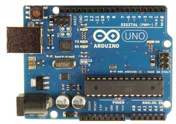
In this project we are going to design a 3x3x3 LED CUBE and connect it to Arduino UNO to get different patterns. For a beginner we will start with a simple pattern.
A typical 3*3*3 LED cube connected to UNO is shown in the image above, the cube consists of 27 Light Emitting Diodes, these 27 LEDs are arranged in rows and columns forming a cube.
There are many types of cubes that can be designed. The simplest one is 3x3x3 LED cube. For 4*4*4 LED cube the work almost triples because you need to do work for 64 LEDs. With each higher number, the work almost doubles or triples. But every cube more or less works on the same way.
3x3x3 LED cube is simplest because there are some advantages to this design like,
- For this cube you need not to worry about power consumption or dissipation.
- Low Power supply demand.
- We don’t need any switching electronics for this cube.
- We need lesser logic terminals so we don’t need shift registers or anything like that.
We need not worry about power drawn by LED because the LED usually stated to work at 20mA current but that is wrong, that number provides the maximum current allowed through the LED. Normally an LED works well from 2mA to 5mA. Anything higher than that, the LED will heat intensely and it will burn out.
So we can drive 9 LEDs carrying 2mA current from a single pin of UNO with no problems. The UNO pins are capable of delivering 20-30mA.
For the cube I chose clear white LED, because I have them spare. You can choose any LED type or color of your choice, but the LED with colored shall work great for this projects.
For the cube we need to spare 12 pins of UNO.
Components Required:
ARDUINO UNO, 220Ω resisters (3 pieces), , power supply (5v),
27 white LEDs, Breadboard wire,

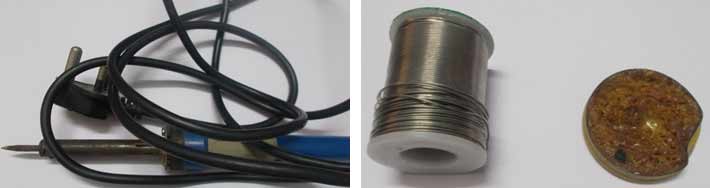
Soldering Iron, Soldering wire and flux,
SR2032 button cell, Some tools,
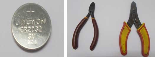
And a empty cardboard box, pencil, ruler and some jumpers.
Building the Arduino 3x3x3 LED Cube:
Step 1:
At first we need to check each LED, once the cube is done if there is any faulty LED present in the cube it would be very difficult to replace, so first we need to check each LED.
This is done by button cell SR2032, it’s a lithium ion battery that has a terminal voltage of 3V it is perfect for checking LED, and one can also use MULTIMETER to check the LED.

After confirming all the 27 LEDs are working keep it aside and lets move one to next step.
Step 2:
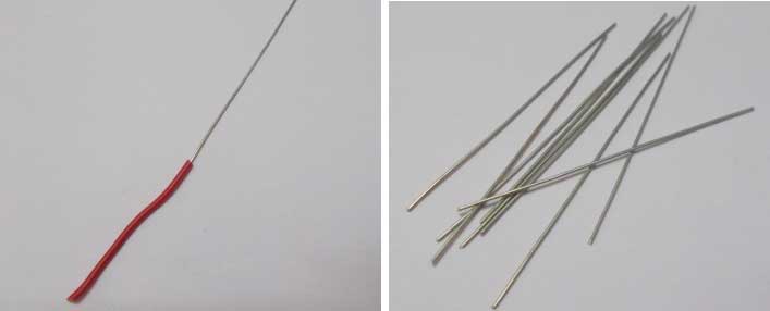
Now take the breadboard wire and peel the layer off the conductor, we can use any wire but breadboard connecting wires works great. After peeling off we will have something as shown in above figure, cut the conductor wire in a length of 7cm and continue the process until we have six 7cm conducting wires (figure below). These wires are used for bridging the LED layers, we will get to this point shortly.
Step 3:
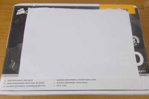
Now we need to take the empty card board box and stick a white paper on top, as shown in the figure. The paper is just for marking the points clearly, there is no specific use for it. Just use cello tape or glue at the corners for holding the paper in place while marking and drilling the holes.
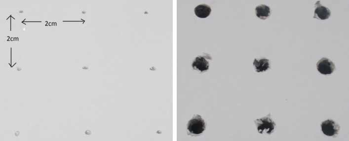
After that take pencil and scale, mark nine points on paper each 2cm apart forming a structure of cube as shown in below figure.
Here we are using 2cm because; the negative terminal of LED is of length 2.5cm. So with 2cm apart, we will have 5mm for soldering one LED to another. Any length higher from it, the LED terminals soldering becomes troubling, with lower length the cube looks very clumsy after finishing. So 2cm would be very appropriate.
After that take a pointy object like a pencil or a pen and poke a hole at each point, make sure you poke a hole just about the size of LED, first poke one hole take the LED fit it in, the LED should not fall through the hole nor the LED should the too tight. While soldering the pins we don’t the LED to move so it should not be lose. If the LED is fitted in the hole too tight we cannot wiggle it out easily, so each time you poke a hole, check it with the LED.
Step 4:
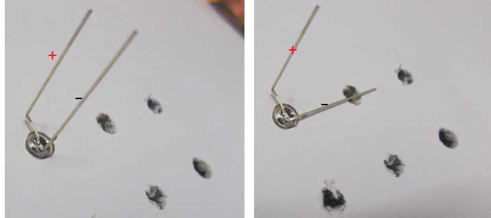
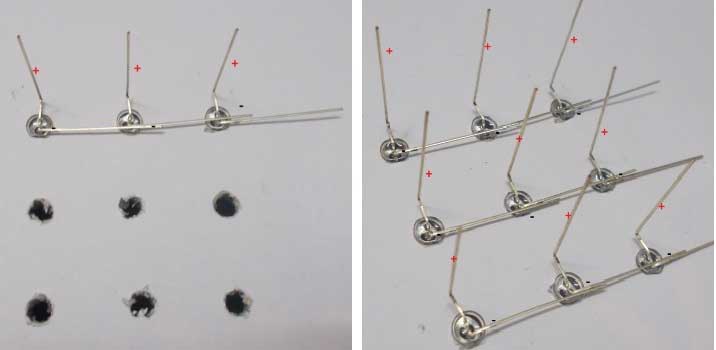
After that, place a LED in one of the hole and bend the positive terminal as shown in below figure.
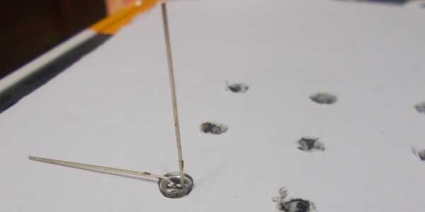
After that, the positive pin should again be bent to form a ‘L’ shape. On close look one can see a small notch on the terminal of LED near the tip, which is where you should bend for ‘L’ shape. After that, bend the negative terminal to the right. This is shown in figure:
Step 5:
The very same way bend three LEDs and arrange them in a row as shown below, this pattern is used throughout the design and there would be no further changes. For more convenience one can bend all the 27 LEDs as done for first one and then can be proceed to the arranging and soldering.
Now bend all the remaining 24 LEDs in the same way as described above, nine of them are bent in the form of a matrix as shown below,
Step 6:
After that solder all the negative joints, this results in three negative terminals, each representing one row. This is shown below.
After that take two conductors wires which we stripped and place them as shown in the figure and solder the six joints of conductor forming a complete matrix.
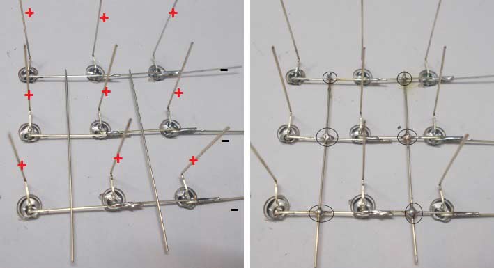
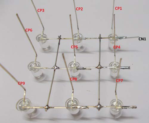
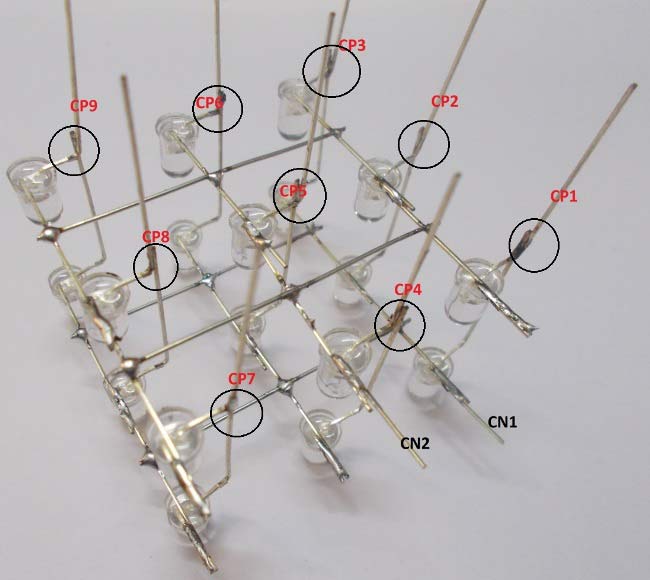
Now all the negative terminals of nine LEDs are connected to each other with this we will have 9 positive terminals (CP1-CP9) and one negative terminal (CN1). After carefully wiggling out the layer one we will have a setup as shown below. Cutoff the extra ends and we will have one layer of LED cube.
Step 7:
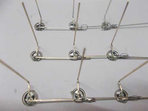
Now we have one of three layers of cubes, we need to develop another two layers by following the same procedure as done for this one. Second and third layer are shown below:

Step 8:
Now we have all the three layers needed to make the LED cube, we are going to stack one over the other to form a cube.
First we take layer1 and layer 2, mount them one over the other. Solder all the common positive representing terminals. This is shown in figure. For instance CP1 of first layer is soldered to CP1 of second layer; CP2 of first layer is soldered to CP2 of second layer and so on. Here we will slide the layers about 5mm, one top over the other, first we need to solder the ends of the layers so that it holds in place and for the layers to be aligned. After that, carefully solder the other terminals. After soldering we will have,
Now we will stack the third and final layer of cube, with this we have completed the cube. The soldering of third layer would be a bit difficult, as the cube terminal be sensitive, if the terminals are wiggled too much, a joint might break internally and soldering an internal joint would be impossible, until the cube is break down. So one should check every joint twice proceeding to the next one.
While soldering cube terminals, the temperature of LED should be kept in mind, if the soldering iron is kept close to LED more than 5 sec, the LED will burn down and replacing it would be a pain, so one should pay attention while soldering the LEDs.
Circuit and Working Explanation
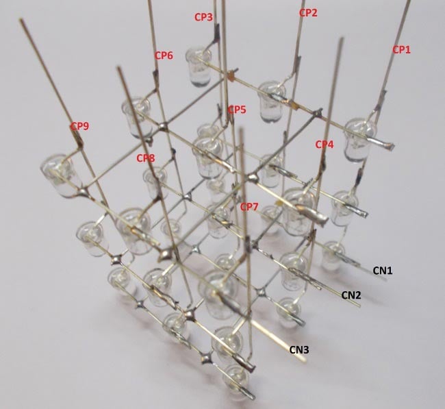
With the cube complete, we have a total of 12 pins. Over which nine are common positive and three are common negative. Each common positive terminal connects the positive terminals of three LEDs and each common negative terminal connects the negative terminals of nine LEDs. So we have nine columns represent the nine positive terminals (CP1-CP9) and three layers represent the three negative terminals (CN1-CN3).
PIN2 ------------------CP1 (Common Positive)
PIN3 ------------------CP2 (Common Positive)
PIN4 ------------------CP3 (Common Positive)
PIN5 ------------------CP4 (Common Positive)
PIN6 ------------------CP5 (Common Positive)
PIN7 ------------------CP6 (Common Positive)
PIN8 ------------------CP7 (Common Positive)
PIN9 ------------------CP8 (Common Positive)
PIN10 ----------------CP9 (Common Positive)
PIN A0 ------------------CN1 (Common Negative)
PIN A1 ------------------CN2 (Common Negative)
PIN A2 ------------------CN3 (Common Negative)
Now, we will connect these 12 pins to the UNO appropriately as shown in the circuit diagram for arduino based LED cube below.

If we want to turn On the single LED i.e. LED in the first layer-second column, we need to power the CP2 pin and ground the CN1.
With the connections established, for the LED in the first layer-second column to glow, we need to program the UNO to pull up the PIN3 (which is connected to CP2) and pull down the PIN A0 (connected to CN1).
All the LEDs are connected this way, so one can choose which LED to be lit, and the programming for the UNO is done appropriately. Here we will give a forever loop to UNO, to glow every LED one after the other continuously. This cycle goes on and on forever.
Complete Project Code
void setup()

{

    for (int i=0;i<11;i++)

    {

        pinMode(i,OUTPUT);    // PINS0-10 are set as output

    }

    pinMode(A0,OUTPUT);    //PIN A0 set as output

    pinMode(A1,OUTPUT);   // PIN A1 set as output

    pinMode(A2,OUTPUT);   // PIN A2 set as output


    digitalWrite(A0,HIGH);    //pull up the A0 pin

    digitalWrite(A1,HIGH);   // pull up the A1 pin

    digitalWrite(A2,HIGH);   // pull up the A2 pin
      /* add setup code here, setup code runs once when the processor starts */
}
void loop()

{

        digitalWrite(A0,LOW);    //layer 1 of cube is grounded

          for (int i=2;i<11;i++)

          {

              digitalWrite(i,HIGH);    //turn ON each LED one after another in layer1

              delay(200);

                delay(200);

                  delay(200);

            digitalWrite(i,LOW);

          }

        digitalWrite(A0,HIGH);    //layer1 is pulled up


          digitalWrite(A1,LOW);   // layer 2 of cube is grounded

          for (int i=2;i<11;i++)

          {

              digitalWrite(i,HIGH);   // turn ON each LED one after another in layer2

                            delay(200);

                            delay(200);

                            delay(200);

              digitalWrite(i,LOW);

          }

        digitalWrite(A1,HIGH);    // layer2 is pulled up


        digitalWrite(A2,LOW);    // layer 3 of cube is grounded

        for (int i=2;i<11;i++)

        {

            digitalWrite(i,HIGH);    // turn ON each LED one after another in layer3

                          delay(200);

                          delay(200);

                          delay(200);

            digitalWrite(i,LOW);

        }

        digitalWrite(A2,HIGH);    // layer3 is pulled up
}
Comments
Hello,
I made this cube and it works great !!!
In the youtubemovie i see that you programmed different cycles for the leds, can you plzzz email this sketch to me ?
I work with kids from 4 till 12 and am learning and making arduino projects with kids from 8 years old and it would be a great project to make with them and learn and program the leds ...
Hope to hear
Thanks
Hi Martjin,
You are doing Great Job!
We have already given the program in the Article (above the Video), the program is same that we used in our Video.
Thanks
It`s nice idea
it's nice
very help full to made quib
very....very.... thank's
That's work great
Can U share more code for me
Thanks a lot :)))
made it ;)
Is it possible for me to build a larger 8x8x8 cube with similar schematic
I will try this LED cube. But i think its not that much code. So it would be nice if you could share some more.
I am not very good in programming so i would be happy about some help. Thanks for the nice instruction.
Hope you will repy soon.
Love yours baun.
Had a go at this and built it on perf board. It was a bit fiddly soldering the LEDS. I used a piece of scrap timber as a jig. The cube worked first time. Have modified the code a bit to find out about how it was working. Great little project.
Hello . Great job. You are doing. I am older person and. It makes a. It difficult holding g still, while I solder. I shake so bad. I clip work so my stand can hold the board to allow me to solder.also made a nice little jig to hold my work so I can consentrate on holding still while solder .
Thank you so very much on your sharing. Thank you.
can we use 100 ohm resistances instead of 220 ohms
I ve done it . It was so impressive . But I need different code. Pls can u. Send me different code.
Great Job.
Code is short for beginners to understand .
But this is an overly simplistic approach to LED cubes where lighting multiple LEDs at the same time is also done. Maybe you could make a tutorial on that for others too.
Good Luck!

NICE