

Previously we have built many types of charger circuits, that incudes Solar mobile Charger, Float charger circuit, 12v Battery charger, Power bank circuit etc. Today we are going to build charger circuit for charging Ni-Cd Battery. The process of charging Nickel cadmium batteries can be done in two ways:
- Fast charging
- Slow charging
The Fast charging requires a proper shutdown after full charge. Unlike a Lead acid battery or a lithium battery, Ni-cd battery cannot take up a float charge. Also, the shutdown of charger after full charge is not simple. It has to be done based on an algorithm which senses the temperature of the battery and steady decrease in voltage after charge completion. Another part is that the battery has to be fully discharged before fast charging.
Hence, here we are going to make a simple slow charger which can charge a Ni-cd battery at lower and safer currents. This process without auto-shutdown will not damage a cell as much when compared to a fast charger without auto-cut off.
Slow chargers can be used to overcome self-discharge. A Ni-Cd battery self-discharges at a rate of 15-20% per month which is higher when compared to 5-10% per month of a Lithium battery. But, it is lower when compared to a Ni-MH battery whose self-discharge is 20-30% per month.
Ni-Cd Battery Charging:
The electrochemical device that supplies energy to the external circuit through an internal chemical reaction is called a Cell. A combination of these cells either in series or parallel connection is called a Battery.
Below is the specification sheet of few Ni-Cd batteries of AA and AAA sizes,
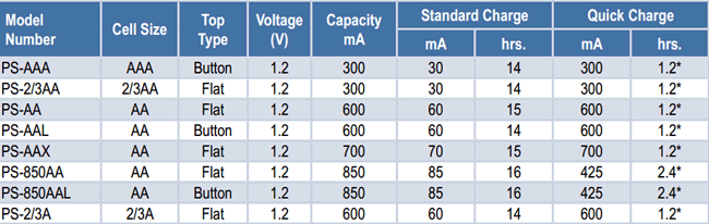
The difference between the standard charging and quick charging is based on the charging voltage, charging current and the cut off method or algorithm.
A fast charging requires precise cut off of power at the end of charge by using the cell temperature or negative change of voltage. The different types in which the Ni-Cd battery can be charged are as below,
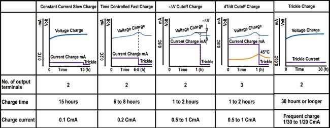
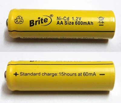
The battery used here is as below which is of capacity 600mAh and indicates us to charge the cell at 60mA which is 0.1C slow charging recommended. Hence, we have done constant current slow charge.
Components Required:
- LM317 – 2Nos
- 1N4007 – 4No.
- Capacitor, 100uF (Electrolytic) – 1No.
- AAA or AA battery holder – 1No
- POT (100Ὠ) – 1No.
- LED (Red -1)
- Resistors (1kὨ -1; 560Ὠ -1; 100Ὠ -2)
- Perforated Dot board
- Connecting wires
Ni-Cd Slow Charger Circuit Diagram and Explanation:

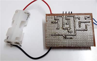
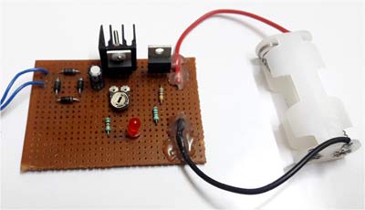
This is How the circuit looks on Perf Board:
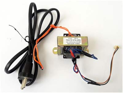
1. Step-down Transformer:
A step down AC transformer with the rating of 230V to 15V, 1Amps is used here. Even though the output current capacity of transformer is at 1Amps, the allowable continuous current is only 0.4Amps for safe operation. A transformer with either 230V/0-15V or 230V/15-0-15V can be used.
2. Bridge Rectifier:
Full wave bridge rectifier converts AC supply into DC supply through a process called rectification and. A rectifier used here is done using four diodes in bridge configuration.
3. Voltage Regulator Circuit:
Here LM317 is used for voltage regulation; it is a three terminal adjustable regulator
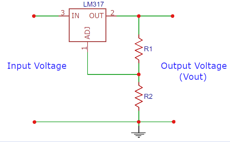
Thus, the required output voltage is 1.45V max to charge the battery.
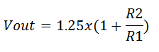
VOUT = 1.25 * {1+ (100/560ohm)}
VOUT = 1.47v
This LM317 Voltage Calculator can be used if you are looking for some calculator to calculate the resistor or to plan the output voltage.
4. Current Limiter Circuit:
Since the charging current for a 600mAh battery will be 60mA. The appropriate Resistor has to be calculated,
IOUT = 1.25 / R
Therefore, R is set to 21Ὠ to limit the current to 0.06A.
Working of Ni-Cd Battery Charger Circuit:
The open circuit voltage without Battery appears as 1.5v which can be seen from the below picture,
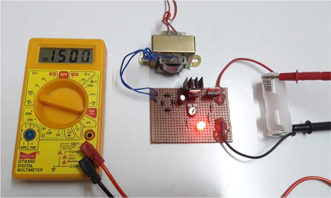
As mentioned earlier, the output voltage is 1.49V and the current is limited to 60mA and the Red LED indicates the Charging condition of the battery.
Comments
Yeah you are right, the parts list is messy here... just skip the parts list and dive straight into the circuit diagram. Its a simple circuit and is very well explained on how each segment of the circuit works. The 100 ohm pot is not needed. The 25 ohm resistor is used to set the current limit of LM317 IC which is also explained above. I am pasting it again here
"4. Current Limiter Circuit:
Since the charging current for a 600mAh battery will be 60mA. The appropriate Resistor has to be calculated,
IOUT = 1.25 / R
Therefore, R is set to 21Ὠ to limit the current to 0.06A."
Oops i found another glitch in the circuit, the resistor in series with the LED is shown in the diagram as 1k2 but in the parts list is 1k. I''m sure the 100 ohm resistor shown in the diagram would be the 100 ohm pot. and please explain the reason for the 25 ohm resistor between the two regulators that doesn't appear in the parts list.
No, the 1k or the 1.2k resistor is just a current limiting resistor for the LED and its okay if you use either 1K or 1.2K.
The reason for 25 ohm resistor is already explained in the above comment. The 100 ohm pot is not used anywhere and its not required for the functioning of the circuit
I, m more exciting about what you,re doing

Hi guys not sure what's going on in this circuit but the parts list shows a 100 ohm pot even though it doesn't appear in the circuit diagram. Also the circuit diagram shows a 25 ohm resistor between the two LM317 voltage regulators, but this resistor is not mentioned in the parts list. I feel some of these projects need a wee bit of proof reading before being published, which i would be more than happy to do