

A float charger, also called as maintenance charger or smart charger, is used to charge a lead acid battery to top-up the self-discharge capacity. Self-discharge happens in a battery if not in usage for long time i.e., the terminal voltage begins to decrease. If this float charger is connected to the battery the self-discharged capacity can be topped up which is to full charge level. So here we are building Float Charger Circuit for 12v SLA Battery (Sealed Lead Acid Battery).
It is advisable to use this float charger occasionally to charge from empty. This prevents the sulfation in batteries so that the life of the batteries is increased. Also, the maximum capacity of the individual cells can be restored. Float charger is compatible to turn itself ON when the battery voltage reaches a lower potential and turn OFF when the battery voltage reaches a higher potential.
The maintenance free VRLA battery are of different types like Flooded lead acid battery, Gel battery, AGM battery. The only important point to consider is the shutdown of charger after full charge to prevent the overcharging. If the automatic shutdown is not present, the charger would overcharge the battery which causes a potential failure of cells inside battery. Here is the simple 12V battery charger circuit using LM317 with simple charger with LCD interface done previously,
Battery:
The electrochemical device that supplies energy to the external circuit through an internal chemical reaction is called a cell. A combination of these cells either in series or parallel connection is called a battery. For example, a 12V lead acid battery is made up of a series connection of 6 cells in series. Each cell nominal voltage will be 2V. So, a float charger has to charge each cell of this battery at 2.25V. So, the overall voltage made to 13.5V.
The 12V is the mid-point voltage (MPV) of a battery (50% of total capacity). The full charged battery shows a OCV (Open-circuit voltage) of 13.5V. The battery can be discharged till 10.5 voltage which is 100% DOD.
Below is the specification sheet of motorcycle batteries from Exide industries,
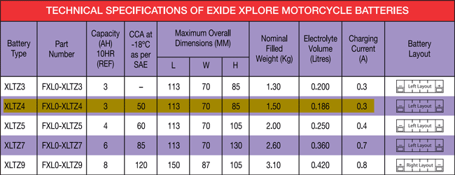
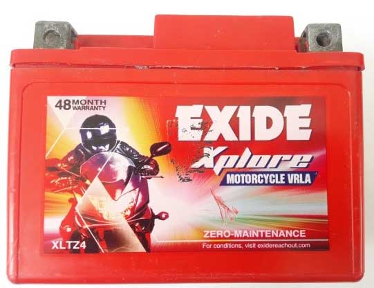
The highlighted line is the battery used in this Float Charger Project. It is a 12V, 4Ah automotive battery used mostly in motorbikes. There in datasheet it specifies the charging current to be 0.3A as safe range. Generally a lead acid battery for motorcycles should be charged in less than 0.1C. In case of traction batteries either Gel type or AGM batteries it can be from 0.1C to 0.15C. Eg:12V, 7Ah battery of traction type, the charging current can be anywhere from 0.7A to 1A.
Components Required:
- LM317 – 2Nos
- LM358 – 1No.
- 1N4007 – 2No.
- Diode bridge RB156 – 1No.
- Relay (5V) – 1No.
- LM7805 – 1No.
- BC547, 2N2907 – Each one
- Capacitor, 1000uF (Electrolytic) – 1No.
- Capacitor, 0.1uF (Ceramic) – 1No.
- Alligator clips – 2Nos
- LED (Blue -1; Green -1; Red -1)
- Resistors (10kὨ -1; 220Ὠ -1; 750Ὠ -2; 1kὨ -5; 1.2kὨ -4; 1.5kὨ -1; 150kὨ -2; 6.2kὨ -4; 4.7Ὠ,2W -1)
- Perforated Dot board
- Connecting wires
Float Charger Circuit Diagram and Explanation:

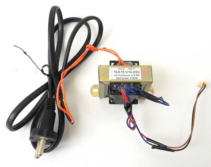
1. Step-down Transformer:
A step down AC transformer with the rating of 230V to 15V, 1Amps is used here. Even though the output current capacity of transformer is at 1Amps, the allowable continuous current is only 0.4Amps for safe operation. A transformer with either 230V/0-15V or 230V/15-0-15V can be used.
2. Bridge Rectifier:
Full wave bridge rectifier converts AC supply into DC supply through a process called rectification and is explained previously in the Full Wave Rectifier Circuit.
A rectifier used here is a full wave bridge rectifier which RB156 is of rating 800V, 1.5A. They come in a single inline package. Thus, comprises of four diodes in bridge connection.
3. Voltage regulator circuit:
LM317 is a three terminal adjustable regulator
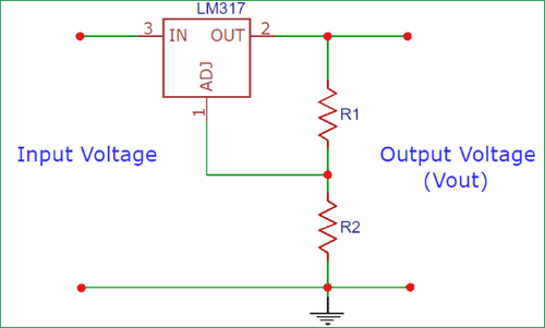
Vout = 1.25 * {1+(R2/R1)}
Thus, the required output voltage is 13.75V max to charge the battery. Since, we have used a diode at the output 0.5V forward drop is also added. Therefore the Vout from LM317 required is 14.25V.
Vout = 1.25 * {1+(2300ohm / 220ohm)}
Here is the LM317 Voltage Calculator for above calculation.
Here, to achieve a R2 as 2300 Ὠ, have made series connection of 1.55K Ὠ with 750 Ὠ. To achieve 1.55k Ὠ four numbers of 6.2 kὨ are paralled.
4. Current limiter circuit:
Since the charging current mentioned in battery datasheet is 0.3Amps. The appropriate Resistor has to be calculated,
Iout = 1.25 / R
Therefore, R = 4.7 Ὠ to limit the current to 0.265A.
5. Automatic-cutoff relay section:
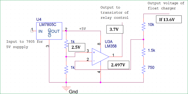
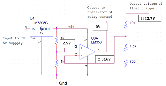
The automatic turning On of the charger and automatic cut-off is carried on using a Relay by controlling the coil excitation. The automatic cutoff section ensures the charging of battery to appropriate level. Once the battery reaches a full charge voltage of 13.6V the relay coil excitation is removed. This way the overcharging of battery is avoided. A comparator circuit is used in inverting condition to achieve this automatic cutoff.
Also, the voltage appears at the output terminals only when battery is connected. Hence this circuit has a protection from short circuit of output terminals. The below pictures demonstrates the operation of Automatic cut-off section.
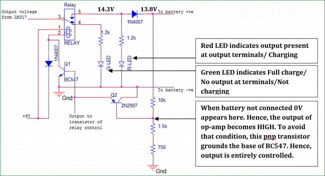
Further the operation of relay, LEDs and control transistors are explained below,
Working of Float Charger Circuit:
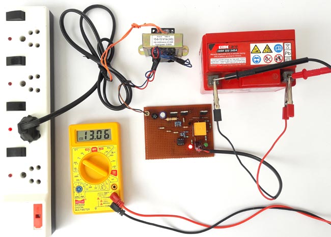
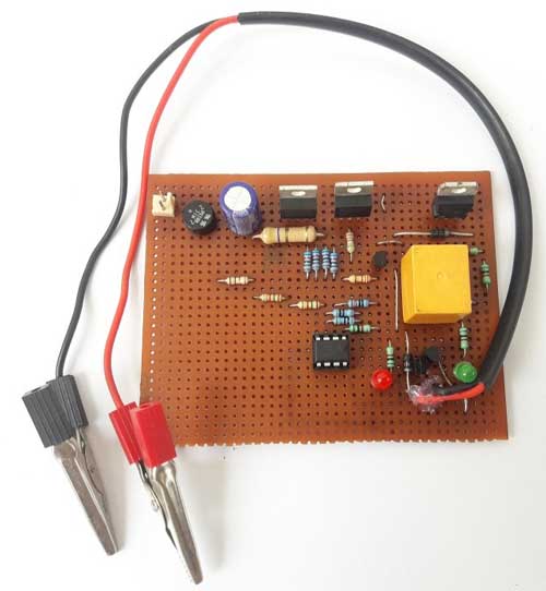
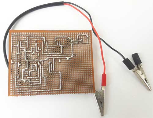
The above circuit is built in a perforated dot board as below,
Now connect the step-down transformer to the input of the module assembled as below and then you will see the Red LED indicates the Charging condition of the battery as explained above with circuit diagram.
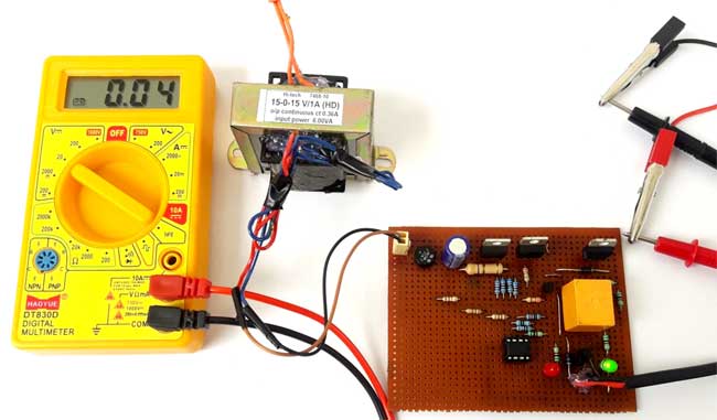
Once the voltage reaches 13.6V the charging is complete and the relay is OFF. Thus, no output appears at the terminals and the Green LED indicates this condition. After this condition is reached the input supply switch can be turned OFF. The relay turns on automatically when the voltage of the battery reaches below 13.6V. Thus, the battery is always in the condition of top-up charging. The self-discharge is refilled and the life of the battery will be improved over a long range.
As mentioned earlier, below pictures explains that no voltage appears at output terminal when the battery is not connected and Green LED indicates the charge completion.
Comments
Microprocessor-based device design for automatic battery charging 12v.
Hi Arvind
Thanks for the project degin.
I got one problem when my bettery reach near by charging level relay continuely on off with high speed . I don't understand why it's happening another question is can I use PNP transistor bc585 instead of 2n 2907 . Please replay soon i am waiting
The repeated turn on and off problem might be due to hysteresis. At what voltage does this problem occurs? Using a Schmitt trigger might solve the problem.
BC585 has low IC than 2n2907 so it not recommended as an alternative
when my battery reach near by charging level 13.5 relay continuely on off with high speed ,circuit is bad ,dont make it!
i want 6v battery to charge ......what are the changes do in the circuit
Is the circuit properly working or not??? please reply me anyone? i neeed to develop this.
or any other suggestion plz give me
Hi Arvind, I get a lot of relay chatter if I use a schmitt trigger could I use the LM358 to create it or should I use a seperate one altogether.
Regards Geoff

Not bad, but for best results with any lead acid cell, they need to by cycled through charge and discharge. This can be done quite slowly. Allowing the battery to discharge, via a small lamp (say 3W) before recharging again will work ok, this system could be incorporated quite easily, most of the circuit is already there... I Winter my Harley battery like this.